Note: Descriptions are shown in the official language in which they were submitted.
CA 02688248 2015-02-26
DEVICE TO PROMOTE HAND SANITIZATION
BACKGROUND OF THE DISCLOSURE
1. Field of the Invention
[0002] Embodiments of the present invention generally relate to the prevention
of
disease transmission through proper hand sanitization and, more specifically,
to a
device to promote hand sanitization.
2. Description of the Related Art
[00031 Nosocomial, or hospital-acquired infections are a leading cause of
death
worldwide: in the US alone, they are responsible for 90,000 deaths annually.
It has
been shown that many nosocomial infections are contracted through contact with
medical staff who have not properly sanitized their hands. Hospitals suggest
that
staff members sanitize their hands before every patient they contact.
Thoroughly
washing and scrubbing with water and antiseptic soap is the traditional method
of
hand sanitization in the hospital, but the time required for proper hand
washing is
unfeasible in a clinical setting because of the large numbers of patients that
require
care.
[0004] Repeated hand washing also causes dermatitis, which makes hands a
better
vector for bacterial transmission. Antiseptic gels and foams provide an
alternative
method of hand sanitization that is as effective as washing with soap and
requires
significantly less time. The widespread use of these antiseptics in hospitals
has not
resulted in decreased rates of nosocomial infections because healthcare staff
still fail
to comply with hand sanitization protocols. Although intentional non-
compliance is
one factor that lowers rates of compliance, it is likely that simply
forgetting to sanitize
between patients is the main culprit. It is well accepted that if health care
workers
improve compliance with hand-washing protocols, the incidence of nosocomial
infections decreases substantially.
1
CA 02688248 2015-02-26
[0005] Therefore, there is a need in the art for a device that promotes hand
sanitization.
SUMMARY OF THE INVENTION
100061 Embodiments of the present invention relate to a device to promote hand
sanitization. In one embodiment of the present invention, the device comprises
an
assembly used to move a door coupled to a sanitizing agent dispenser such that
the
dispenser releases sanitizing agent upon manipulation of the assembly to move
the door.
In another embodiment, the assembly comprises a latch that is coupled to the
door for
latching the door. Upon manipulation of the latching assembly to open the
door, hand
sanitizing agent is automatically released from the latching assembly onto the
hands of a
user that is manipulating the latching assembly.
[0006a] In yet another aspect, the present invention provides a device for
promoting hand
sanitization, the device comprising: an assembly, including a pull handle,
used to move
a door; and a sanitizing agent dispenser, coupled to the assembly, and to a
pump, a tube
and a nozzle, for releasing sanitizing agent upon manipulation of the assembly
to move
the door simultaneously to a hand of a user through the nozzle, wherein the
assembly is
adapted to manipulate a latch of the door.
[0006b] In yet another aspect, the present invention provides an apparatus for
dispensing
sanitizing agent comprising: a door; a latching assembly, coupled to the door,
comprising a pull handle; and a sanitizing agent dispenser, coupled to the
latching
assembly and pull handle, for dispensing the sanitizing agent simultaneously
onto the
hand of a user through a nozzle when the latching assembly is manipulated to
either
open or close the door.
BRIEF DESCRIPTION OF THE DRAWINGS
[0007] So that the manner in which the above recited features of the present
invention
are attained and can be understood in detail, a more particular description of
the
invention, briefly summarized above, may be had by reference to the
embodiments
thereof which are illustrated in the appended drawings.
[0008] Figure 1 depicts a perspective view of a hand sanitizing device coupled
to a door
in accordance with one embodiment of the invention;
[0009] Figure 2 depicts a perspective view of a pull handle in accordance with
one
embodiment of the present invention;
2
CA 02688248 2015-02-26
[0010] Figure 3 depicts a cross section plan view of a pump within the
embodiment of
Figure 2;
[0011] Figure 4 depicts a cross section plan view of the pull handle of Figure
2;
[0012] Figure 5 depicts an exploded view of a twist latch handle in accordance
with
another embodiment of the invention;
[0013] Figure 6 depicts a perspective view of another embodiment of a twist
latch handle
in accordance with another embodiment of the invention;
[0014] Figure 7 depicts a cut away view of push latch assembly in accordance
with
another embodiment of the present invention;
2a
CA 02688248 2009-11-25
WO 2008/153711 PCT/US2008/006505
[0015] Figure 8 depicts a cut away view of a pull handle in accordance with
another
embodiment of the present invention;
[cam Figure 9 depicts a perspective view of a cartridge casing in accordance
with
an embodiment of the invention; and
[0017] Figure 10 depicts a cross-sectional view of a cartridge for storing
sanitizing
agent in accordance with an embodiment of the invention.
DETAILED DESCRIPTION OF THE DRAWINGS
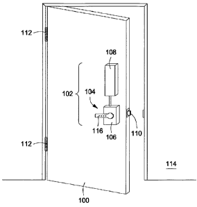
[0018] Figure 1 depicts a perspective view of a door 100 mounted by hinges 112
to
a wall 114 of a room (or enclosure). In accordance with one embodiment of the
invention, the door 100 comprises a device 102 to promote hand sanitization.
The
device 102 comprises an assembly 104 coupled to a sanitizing agent dispenser
106.
The assembly 110 comprises a handle 116 and, in some embodiments, a latch 110
that can be manipulated to open and close the door 100 with respect to the
wall 114.
The sanitizing agent dispenser 104 comprises, or is coupled to, a reservoir
108
containing a liquid or gel sanitizing agent. The sanitizing agent is dispensed
via
the handle 116 of the assembly, such that manipulation of the assembly to open
or
close the door 100 results in the sanitizing agent being dispensed upon a
user's
hand.
[0019] Figure 2 depicts a perspective view of a pull handle 200 (a form of
assembly
used to move a door that may or may not manipulate a latch for the door)
mounted
to a door 100 where the pull handle 200 includes sanitizing agent dispenser
202 in
accordance with another embodiment of the invention. The handle 200 comprises
a
hollow C-shaped tube 220 that is moveably coupled to a pair of handle sleeves
218A
and 218B that are affixed to the door 100. The dispenser 202 comprises a pump
234, a tube 204 from a sanitizing agent reservoir (not shown), a distribution
tube
222, agent supply channels 226 and a permeable foam grip 224. The pump 234 is
mounted on a pair of pump stanchions to the handle sleeve 218A. The pump 234
comprises a pump piston 208, a pump spring 212, and a ball valve 214 that are
organized to pump fluid from tube 204 into tube 222. The tube 222 couples the
fluid
to the channels 226 as discussed below with respect to Figure 4. The
sanitizing
3
CA 02688248 2009-11-25
WO 2008/153711 PCT/US2008/006505
agent penetrates the grip material 224 to contact a hand that manipulates the
handle
220. An alternative to a permeable grip is a handle surface comprising
perforations.
[0020] Within the handle 220 proximate the handle sleeve 218B is a spring
support
232, a spring 230, and a spring plate 228. Together these elements form a
biasing
assembly that maintains the handle inward position such that pulling the
handle
applies force against the bias, causes the pump to pump sanitizing agent and
then
returns the handle to the inward position. In this manner, upon each pull of
the
handle, an amount of sanitizing fluid is pumped out of the handle onto a
user's hand.
[0021] Figure 3 depicts a cross sectional view of pull handle 200 along line 3-
3 in
Figure 2 showing the pump 234 mounted by a stanchion 216 to the sleeve 218a.
An
actuator 300 is coupled to the handle 220 such that movement of the handle 220
relative to the sleeve 218A causes the piston 208 of the pump 300 to force
sanitizing
agent toward the grip. In this manner, the pump 234 is embedded within the
handle
in an unobtrusive manner.
[0022] Figure 4 depicts a cross sectional view of the pull handle 200 along
line 4-4
of Figure 2. A plenum 404 for distributing sanitizing agent to the handle grip
224 is
formed of a central tube 400, a plurality of radial tubes 402 and channels
226. As
the sanitizing agent is pumped into the central tube 400 (coupled to tube 222
of Fig.
2), the agent flows equally into the "spokes" 402, through the channels 226
and the
permeable grip 224.
[0023] Figure 5 depicts an exploded view of an assembly 500 that utilizes a
twist
handle 502 to facilitate pumping sanitizing agent in accordance with another
embodiment of the invention. The assembly 500 comprises a mounting plate 522,
housing 508, and a handle 502. Within the housing 508 is a pump 536 and a pump
actuator 542. The pump actuator 542 couples the handle 502 to the pump 536.
The
pump 536 receives sanitizing agent via a tube 534. An outlet of the pump 536
is
coupled to the tube 512 and, ultimately, to the handle 502. The inlet tube 534
is
threaded through a hole 524 in the mounting plate 522 to couple to a
sanitizing
agent reservoir (not shown).
[0024] The actuator 542 comprises a cam 528 and a push rod 508. The cam 528
is coupled to a pair of pump arms 532 via the push rod 514. The push rod 514
is
coupled, at its first end, to the arms 532 using a pin 530. At its second end,
the
push rod 514 is coupled to the cam via a pin/spacer 518. The cam 528 comprises
a
4
CA 02688248 2009-11-25
WO 2008/153711 PCT/US2008/006505
centrally located aperture 516 that interacts with a latch shaft 540. The
latch shaft
540 (typically, having a square cross section) passes through a matching
shaped
aperture 516. The shaft 540 exits the mounting plate through a hole 520 to
engage
a portion of a conventional latch assembly (not shown). The shaft 540 couples
to the
handle 502 via a hole 510 in the housing. In addition, the tube 512 passes
through
the hole 510.
[0025] The tube 512 supplies sanitizing agent to an agent port 504. The agent
flows into a tray 506 atop the handle 502 such that a user must contact the
agent to
twist the handle 502. Alternatively, the handle may comprise a plenum and
distribution channels to position the agent on the handle 502. A permeable
grip, as
described previously, may also be positioned upon the handle 502, such an
embodiment is described with respect to Figure 6 below.
[0026] In operation, a twisting motion of the handle 502 to facilitate
unlatching a
door causes the pump 536 to distribute sanitizing agent to the tray 506 of the
handle
502. Consequently, the user receives sanitizing agent upon their hand.
[0027] Figure 6 depicts a perspective view of another embodiment of the
invention
that utilizes a twist handle 614 to facilitate pumping of sanitizing agent. A
source
tube 602 couples sanitizing agent from a reservoir (not shown) to the pump
(the
same assembly as shown in Figure 5) located within the housing 604. The shaft
608
is coupled to the handle 614 to facilitate coupling the rotation of the handle
to the
pump as well as other portions of the actuator assembly. The tube 606 carrying
sanitizing agent from the pump is coupled to the grip 610 of the handle 614.
The
handle 614 is covered with a permeable foam 612 such that the sanitizing agent
permeates the foam. With each grasp of the handle 614, a user will receive
sanitizing agent upon their hand. Other forms of sanitizing agent distribution
are
also within the scope of the invention such as a plenum and a perforated
handle
surface and the like.
[0028] Figure 7 depicts a cross sectional view of another form of assembly 700
wherein a latch may be actuated by a push panel or push bar 702 and the
sanitizing
agent dispenser 750 is incorporated into the assembly 700 to dispense agent
upon
depression of the push bar 702. Coupling the push bar to a door latch forms an
alternative embodiment of the invention. The dispenser 750 comprises a
sanitizing
agent reservoir 752 and a pump 720. The reservoir 752 comprises a casing 706
and
CA 02688248 2009-11-25
WO 2008/153711 PCT/US2008/006505
a replaceable cartridge 708 (further described with respect to Figure 10,
below). The
cartridge 708 is coupled to the pump via a cannula 710 that extends through a
cap714 into the cartridge 708. Upon installation of the cartridge 708, the
cannula
710 pierces a septum 716 to position the apertures 712 into the agent. The
apertures 712 couple agent to the tube 754, which carries the agent to the
pump
720. The pump 718 comprises a ball valve 718, a spring 724, and a piston 726.
The
piston 726 is coupled to the bar 702 such that depression of the bar 702
causes the
pump to push fluid through the tube 722 to the outlet 728 at the surface of
the bar, or
button 702. The bar is guided in its motion by guide pins 730.
[0029] In operation, a user depresses the bar or button 702 and the pump is
actuated to supply a stream of sanitizing agent to the outlet 728. The agent
is
applied to the person's hand that pushes the bar or button to move a door. The
actuator for the door may be remote, as in a handicapped door opener, or may
be
local and built into a portion of the bar proximate the dispenser 750.
[0030] Figure 8 depicts a cross sectional view of another form of assembly 800
wherein a latch may be actuated by a pull panel 806 and the sanitizing agent
dispenser 850 is incorporated into the assembly 800 to dispense agent upon
pulling
of the pull panel 806. Coupling the assembly 800 to a latch forms an
alternative
embodiment of the invention. The dispenser 850 comprises a sanitizing agent
reservoir 752 and a pump 808. The reservoir 752 is substantially similar to
the
reservoir 752 described above and further described with respect to Figure 10,
below. Once installed, the apertures 712 couple agent to the tube 818, which
carries
the agent to the pump 808. The pump 808 comprises a ball valve 816, a spring
812,
and a piston 810. The piston 810 is coupled to the panel 806 such that pulling
of
the panel 806 causes the pump 808 to push fluid through an outlet nozzle 814
located proximate the pull panel 806. The pull panel is guided in its motion
by a
pivot 804.
[0031] In operation, a user pulls the panel 806 and the pump 808 is actuated
to
supply a stream of sanitizing agent to the outlet nozzle 814. The agent is
applied to
the person's hand that pulls the panel to move a door. The actuator for the
door may
be remote, as in a handicapped door opener, or may be local and built into a
portion
of the panel proximate the dispenser 850.
6
CA 02688248 2009-11-25
WO 2008/153711 PCT/US2008/006505
[0032] Figure 9 depicts a perspective view of one embodiment of a reservoir
750.
The reservoir comprises a casing 708 and a cartridge 706 that contains the
sanitizing agent. The casing comprises a latch 902 and a latch release button
904
as well as a hinge 906. Upon depressing the latch release button 904, the
latch is
released to enable pivoting an outer casing 708A away from the inner casing
708B
to facilitate access to the cartridge 706. In this manner, a cartridge 706 can
be
readily replaced. The casing may have a viewing port to enable checking
whether
the sanitizing agent cartridge is empty. Although the hinge and latch are
shown at
the top and bottom of the casing, in other embodiments the casing may be
hinged
along the top or side and a latch may or may not be used.
[0033] Figure 10 depicts a cartridge 706 for providing a source of sanitizing
agent to
the device to promote sanitization as described above. The cartridge 706
comprises
a container 1000 and a cap 1004. The container 1000 is a bottle or bag capable
of
containing a liquid or gel. The container has an opening 1012 that is
surrounded by
threads 1002. The cap comprises a threaded annular slot, where the threads
interface with the threads of the container 1000. The cap 1004 further
comprises a
rubber septum 1014 and a seal 1010. The seal 1010 ensures that the sanitizing
agent is maintained in sterile environment. The seal also retains the agent
when the
cartridge has the opening facing downward. The seal 1010 is irreversibly
penetrated
and opened by the cannula when the cartridge 706 is installed in the casing
(see
Figure 9).
[0034] Although the foregoing description used a door to a room as an example
of
an object that the device to promote hand sanitization can be incorporated,
those
skilled in the art will realize that other doors and moveable objects can be
benefited
by incorporation of the invention. For example, desk drawers, file drawers,
cabinet
doors or drawers or any other object that is repeatedly touched and moved by
various persons can utilize the device to promote hand sanitization. Generally
speaking, the device can be incorporated into any form of handle for a door or
other
object. Such devices may or may not include latching assemblies.
[0035] While the foregoing is directed to the illustrated embodiments of the
present
invention, other and further embodiments of the invention may be devised
without
departing from the basic scope thereof, and the scope thereof is determined by
the
claims that follow.
7