Note: Descriptions are shown in the official language in which they were submitted.
CA 02688352 2014-03-31
HAND-HELD TRACE VAPOR/PARTICLE DETECTION SYSTEM
BACKGROUND OF THE INVENTION
1. Field of the Invention
The present invention relates to the field of detection
apparatus used to screen for the presence of explosives and
other chemical entities.
2. Background Information
Screening system for threat compounds such as explosives
as well as chemical and biological weapons must be able to
collect, concentrate, and analyze trace samples quickly and
accurately. Many detection technologies such as mass
spectrometry (MS), ion mobility spectrometry (IMS), gas
chromatography (GC), optical spectroscopy, etc. have been
developed over the years and trace detectors now exist that
can detect a wide range of explosives and chemical weapons,
and to a lesser extent biological weapons. Much less
attention has been given to collecting and delivering sample
to the detectors, yet collection and delivery is arguably
1
CA 02688352 2009-11-10
WO 2009/134606
PCT/US2009/040280
the most challenging part of a screening system since it must
adapt to a wide range of applications and screening scenarios.
Furthermore, whereas the specificity of a detector is the key to
minimizing false positive rates, the collector/concentrator is
of vital importance for maximizing detection rates, since if a
trace sample is not delivered to the detector, it will result in
a non-detect event.
An effective sampling system should preferably have the
following operational characteristics: (1) access the volume
. containing the contamination, (2) dislodge the contamination,
particularly for particles that can stick tightly to materials,
(3) concentrate collected vapor and particle material, (4)
deliver the material to a trace detector in a step that involves
vaporization, and (5) minimize cycle time and carryover effects.
An effective collector/concentrator sampling system for
explosives and other threats must be able to collect vapor and
particles, and if delivering to a trace detector, convert the
particles to vapor. Several vapor and particle sampling systems
have been developed in the past, however, they are either
. optimized for one or the other phase, or are not suitable for
trace. detectors.
U.S. Pat. No. 6,087,183 issued to Zaromb discloses a method
to collect vapor and particles on a liquid film. However, a
liquid concentrate is not the preferred medium for a trace
2
CA 02688352 2009-11-10
WO 2009/134606
PCT/US2009/040280
detector, which is designed to analyze vaporized sample. U.S.
Pat. No. 5,914,454 issued to Imbaro et al. discloses a spray of
charged droplets to collect vapor, liquid, and particles, but
the sample is also concentrated in a liquid. U.S. Pat. No.
5,855,652 issued to Talley discloses a method for collecting
particles and microorganisms into a water sample. U.S. Pat. No.
4,092,218 issued to Fine et al. discloses a method for the
selective detection of explosives vapors, but does not show that
it is capable of collecting particles.
A series of patents issued to Linker et al. disclose
methods to collect explosives particles for trace detectors that
have some capability to collect vapor as well. U.S. Pat. No.
6,345,545, issued to Linker et al., discloses a two-stage pre-
concentrator that uses a metal or other electrically conducting
screen to capture particles. Some vapors may also stick to the
screen, however, the surface chosen for particle collection is
not in general optimal for vapor collection. U.S. Pat. No.
6,523,393, issued to Linker et al., discloses a hand-portable
embodiment of the metal screen particle concentrator that makes.
use of a removable screen that is manually placed first in the
high volume flow region and second in the detector region.
The above patents disclose various techniques for sample
concentration. Another important component to an overall
screening system is a sampling probe for collecting vapor and
3
CA 02688352 2009-11-10
WO 2009/134606
PCT/US2009/040280
particles, particularly from hard-to-remove locations and
surfaces. U.S. Pat. Nos. 6,334,365 and 5,915,268 issued to
Linker et al., disclose the use of air-jets to help dislodge
particles from the clothing of individuals in a portal device
for screening people for explosives. U.S. Pat. No. 6,708,572,
issued to Jenkins et al., also discloses the use of air-jets to
dislodge particles from individuals in a portal device.
Trace detectors are used extensively in airports and other
venues to screen baggage for explosives. The method typically
used to remove material from surfaces are swipes of cloth. This
method is effective at collecting residue, however, it requires
manual operation and therefore may produce unpredictable results
in the collection process. Furthermore it is not effective at
collecting vapors.
Another need for threat detection is an efficient means to
deliver the collected sample to the detector. U.S. Pat. No.
7,299,710 issued to Syage discloses a system to collect vapor
and particle samples onto a removable concentrator that could be
inserted into a trace detector. It is desirable to integrate a
. detector with the sampling system in order to have a combined
handheld sampler/detection system. Various systems in the past
. have been developed based on IMS or GC detection. However,
these methods generally only collect vapor or particles and not
both. In cases where both vapor and particles are collected,
4
CA 02688352 2009-11-10
WO 2009/134606 PCT/US2009/040280
these samples would be delivered to separate detectors and not a
single detector. Furthermore, these devices did not provide a .
means to obtain a second dimension of separation in order to
improve analysis accuracy.
BRIEF SUMMARY OF THE INVENTION
A hand held detector system that has a housing with a
passage that can receive a sample, and a concentrator that
captures the sample. The hand held system further includes a
single detector coupled to the concentrator and a fluid system
that provides fluid communication between the housing passage
and the concentrator, and between the concentrator and the
detector. The system is powered by a battery.
BRIEF DESCRIPTION OF THE DRAWINGS
Figures 1A-Care illustrations of a vapor/particle sampling
and detection system;
Figure 2A-B are illustrations of another embodiment of a
vapor/particle sampling and detection system;
Figure 3 is a graph showing absorption intensity as a
function of runs;
CA 02688352 2009-11-10
WO 2009/134606 PCT/US2009/040280
Figure 4 is a diagram showing a method for temperature
programmed thermal desorption of multiple collected compounds;
Figure 5 shows a timing diagram for the sampling and
detection system;
Figure 6 shows another timing diagram for the sampling and
detection system;
Figures 7A-B show an embodiment of a vapor/particle sample
cartridge; and,
Figure 8 shows an embodiment of a handheld vapor/particle
=
sampling and detection system.
DETAILED DESCRIPTION OF THE PREFERRED EMBODIMENT
Disclosed is a hand held detector system that has a housing
with a passage that can receive a sample, and a concentrator
that captures the sample. The hand held system further includes
a single detector coupled to the concentrator and a fluid system
that provides fluid communication between the housing passage
and the concentrator, and between the concentrator and single
detector. The system is powered by a battery. The system may
include a controller that heats the concentrator with a
temperature profile that causes a first trace molecule to desorb
at a time different from the desorption of a second trace
6
CA 02688352 2009-11-10
WO 2009/134606 PCT/US2009/040280
molecule. The temperature profile allows the trace molecules to
be sent separately to the detector, which improves the accuracy
of trace detection. The system components are powered by a
battery.
= The system contains filter components for collecting and
concentrating vapor and particles from objects and surfaces and
= a detector to analyze the collected sample. The system housing
may emit air-jets to help dislodge particles from surfaces and a
heating lamp to help vaporize compounds on surfaces or objects.
The sampling system is especially useful for screening
explosives and other illicit chemicals and toxins on people,
baggage, cargo, and other objects.
The disclosed system is unique in being able to collect
particles and vapors off of surfaces, concentrate the sample
= onto a concentrator and deliver the sample to a single detector
for analysis all in one hand held unit. The handheld unit
further has temperature programmed desorption for improved
analysis accuracy, and a reusable sample cartridge that can be
adapted to other external detection systems.
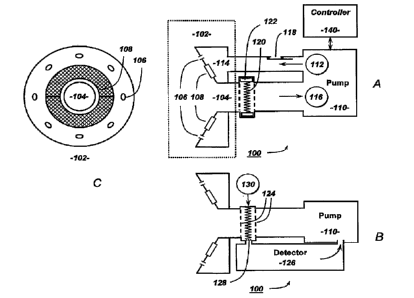
Referring to the drawings more particularly by reference
numbers, Figures 1A-C show an embodiment of a collection and
detection system 100. The system 100 includes a sampling head
102 that has an intake port 104 and a plurality of air-jet
7
CA 02688352 2009-11-10
WO 2009/134606 PCT/US2009/040280
= nozzles 106. The head 102 may also have a heater assembly 108.
The assembly 108 may be one or more heat lamps. The position of
the air-jet nozzles 106 and the lamps 108 can be reversed from
what is shown, or can have other configurations. The system 100
may include a pump 110 that creates a positive pressure air flow
112 in passage 114 to pressurize the air-jet nozzles 106 and a
negative pressure air flow 116 to pull sample through the intake
port 104. For the embodiment shown in Figs. 1A-C, the pumping
action may be continuous during sample collection such that air-
jets are flowing out of the nozzles 106 while sample is being
= pulled in through the intake port 104. The heater 108 is
typically on during the sampling period, however, it may be
desirable to turn the heater 108 on for only a part of the
sampling period, such as to limit vapor collection to the latter
part of the sampling period.
The system 100 may include an exhaust valve 118 that can be
opened to drop the pressure within passage 114 and terminate the
flow of the air-jets from nozzles 106, while sample is still
being pulled in through the intake port 104. The system 100
includes a concentrator mesh 120 that collects particles and
vapor from the sample. Opening the exhaust valve 118 may be
useful for cooling the concentrator mesh 120 after an analysis
cycle is complete and/or for collecting only vapor from a
surface when the heater 108 and pumps 110 are on.
8
CA 02688352 2009-11-10
WO 2009/134606 PCT/US2009/040280
The air-jets are aimed at a surface or object and the air
impact loosens particles that are then pulled through the
sampling port 104. The heater 108 increases the temperature of
the surface or object and provides a corresponding increase in
the vapor pressure of more volatile compounds in order to
' enhance the collection of vapor. The particle and vapor sample
is pulled through the concentrator mesh 120. The concentrator
mesh 120 collects both particles and vapors. The concentrator
mesh 120 can be installed in a removable cartridge 122.
The concentrator 120 may have shutters or valves 124 that
can open during sample collection and close during sample
delivery to a detector 126 as shown in Fig. 1B. The concentrator
120 can also have a valve or shutter 128 that is closed during
sample collection and opened during sample delivery to the
detector 126. The sample that is collected on the concentrator
mesh 120 is delivered to the detector 126 by thermal desorption,
but passing a current through the mesh if it consists of metal,
or by other means. The delivery of sample to the detector 126
can be assisted by a pick up flow 130 provided by the
overpressure side of the pump 110 or from another source such as
a supplemental gas supply. The detector 126 may also use a pump
flow from pump 110 to draw the sample into and out of the
detector 126. A controller 140 controls all the functions of
the sampling and detection system.
9
CA 02688352 2009-11-10
WO 2009/134606 PCT/US2009/040280
= Figures 2A-B show another embodiment of the system 200 that
has a rotary mechanism 202 to switch between sampling flow (Fig.
2A) and detection flow (Fig. 2B). As described in the
embodiment shown in Figs. 1A-C, the detection flow can be
assisted by a supplemental flow 130 provided by the pump 110 or
another source of positive pressure. The detector flow can also
be assisted by the pump 110. The system 200 may also have the
exhaust valve 118 described and shown in Fig. 1.
Figure 3 is a graph that shows the effectiveness of the
disclosed particle/vapor concentrator system. The plot shows
the detection signal resulting from the collection of
nitroglycerin (NG) vapor onto the sample mesh and then thermal
desorption into a MS detector. The numbers over the peaks refer
to the mass in nanograms of NG that was vaporized into the
sampling flow. Based on a detection limit of 2 ng, the results
show an efficiency for collection, desorption and introduction
into the detector of about 10-30%.
There are many types of trace detectors for analyzing
compounds that have been desorbed into the vapor phase. MS is
the most accurate detector, however, such detectors cannot be
reduced in size and weight enough to be used for a handheld
detection system. Historically hand held detectors have
utilized, IMS, GC, or some other simple detector. These devices
CA 02688352 2009-11-10
WO 2009/134606 PCT/US2009/040280
have low resolution and if presented with a very complex mixture
can give many overlapping signals. This can lead to false
positive responses when an interferent overlaps with the
expected signal for a targeted threat compound. The sampling
and concentration technology disclosed here collects both
= particles and vapors and can sample a wide variety of compounds.
This can lead to signal confusion with low resolution detectors.
This problem is minimize by separating the introduction of the
collected sample into the detector using a technique to
thermally control the desorption of the sample. By using a
programmed temperature ramp on the sample mesh 120, compounds
with higher vapor pressure (i.e., lower boiling points) will
desorb before compounds with lower vapor pressure. This method
is illustrated in Figure 4, which shows the heating applied to
the sample mesh 120 such that the temperature ramps up at a
= controlled rate. As an example, we show the possible desorption
signal of three trace molecules with different vapor pressures.
This example shows that it is possible to separate the desorbed
sample so that the detector 126 does not have to analyze all the
trace molecules at the same time. This method provides a
technique to expand the signal from one dimension to two
dimensions, which greatly increases the accuracy of a detection
system.
11
CA 02688352 2009-11-10
WO 2009/134606
PCT/US2009/040280
Figure 5 is a timing diagram that shows an entire sequence
of sample collection, desorption/detection, and recycle for the
handheld detection system. During the collection period, the
sampling valve 124 is open, or for system 200 the rotary valve
202 is in the position that allows for sampling flow (Fig. 2A).
During the collection period, the air-jets 106 and heating
source 108 are on. During the desorption/detection step the
sampling valve 124 is closed, or the rotary valve 202 is in
position for detection flow (Fig. 2B). The air-jets 106 and
heating source 108 are off during this step. The sample mesh
. 120 is then heated to thermally desorb the collected particles
and vapor. Fig. 5 shows a ramped heating rate, as described
earlier and illustrated in Fig. 4, in order to separate in time
the desorption of the variety of compounds that are collected.
Before the next sampling cycle, it may be desirable to clear
down the sampling mesh 120 by allowing all compounds to
thermally desorb and then cool the mesh 120 with a flow of
sample air by actuating the sample valves 124 or 202 in the
sample flow position. Another way to cool the sample mesh 120
is to use a thermoelectric device such as a Peltier cooler. The
. advantage of an active cooler is rapid cooling and also the
capability to take the temperature below ambient temperature
thereby improving collection efficiency. The timing for the
12
CA 02688352 2009-11-10
WO 2009/134606
PCT/US2009/040280
thermoelectric cooling could be the same as that for the
activation of the intake port 104.
Figure 6 shows a timing diagram for another mode of
operation. In this case, the detection system 100 or 200 can be
operated such that the collection mesh 120 is cooled after the
. desorption/detection period by activating the intake port 104
and deactivating the air jet nozzles 106 and heater lamp 108
(e.g. opening the exhaust valve 118). For the next collection
period the air jet nozzles 106 can be turned on to collect
particles and then turned off after a certain time. For the
remainder of the collection period the heating lamp 108 and
intake port 104 can remain on for efficient collection of vapor.
The idea is that the air jet nozzles have finished collecting
particles over the sampling area, but the vapor pressure of
compounds over the sampling area are just reaching significant
. levels and these are best collected without the air jet stream,
which can dilute the vapor. Another method is to turn the air
jet nozzles 106 on for a series of short intervals or bursts.
In this way, particles can be loosened from surfaces, but
without the concern that a continuous air jet might sweep
particle and vapor sample material away from the intake port
104. =
13
CA 02688352 2009-11-10
WO 2009/134606
PCT/US2009/040280
U.S. Pat 7,299,710 issued to Syage ("the '710 patent")
describes a particle/vapor concentrator that include two
parallel meshes. One mesh is constructed from a metal' material
to collect particles. The other mesh is constructed from a non-
metallic chemically adsorbing material for collecting vapor.
The metal mesh is heated with a current to vaporize the
particles and also to heat the vapor mesh to liberate the vapor.
Figures 7A-B show an embodiment of a concentrator 300 that
includes two metal meshes 302 and 304 that sandwich a chemically
adsorbing vapor mesh 306. The mesh sandwich can be held
. together by a pair of metal bands 308 that can also serve as
electrical connectors to receive a current that flows through
the metal meshes 302 and 304. The concentrator 300 can have a
handling tab 310 for handling and for inclusion of
= identification markings such as a bar code 312.
The '710 patent describes power requirements for a handheld
particle/vapor sampler/concentrator. The systems 100 and 200
add a detection function while still minimizing power so that
the systems are hand held devices. The additional requirements
for the addition of a detector 126 such as illustrated in Figs.
1 and 2 are power and sample air flow. IMS, GC, optical, and
other compact detectors for vapor analysis have been described.
Also described is a variation of IMS, which is often referred to
14
CA 02688352 2009-11-10
W02009/134606 PCT/US2009/040280
as field axial IMS (FAIMS) or differential mobility spectrometry
(DMS). The DMS is the most advanced of the detectors listed and
we will use this example to establish the power requirements for
a handheld detection system. For a handheld sampling system we
have demonstrated the use of a 150 L/min pump 110 and operation
of air jets 106 and heater 108 that consumes on average 30 W of
power. A DMS detector consumes about 10 W average power for a
total of 40 W average power during operation. Assuming the use
of a standard off-the-shelf rechargeable nickel-cadmium battery
than we can obtain 40 Watt-hour of use in about 2 lb. For a 12
s overall cycle time, this would give up to 300 sample analyses
per battery charge, which represents a very useful performance.
More advanced battery technologies, such as lithium ion can up
to double the battery life described above. The system
controller can count a number of samples collected and analyzed
by the system.
Figure 8 shows an embodiment of a handheld trace detection
system 400 based on the operation described above and
represented in Figs. 1-7. The intake port is denoted by 402 and
contains the air jet nozzles and heater shown in Figs. 1 and 2.
A sample cartridge (not shown) can be loaded through a cartridge
.slot 404. Power can be provided by a battery 406 and controlled
through switch 408. The system 400 can be controlled by a
programmable controller and an interface such as a liquid
CA 02688352 2009-11-10
WO 2009/134606
PCT/US2009/040280
crystal display monitor and touch screen or keypad denoted by
410. The number of collected samples can be displayed by the
monitor 410. The detector 126 can mount in various locations,
but for this embodiment is shown to mount on the bottom 412 of
the handheld unit. Other configurations are possible and this
technology can also be configured for non handheld uses such as
a desktop analyzer or part of a larger screening system.
The systems and devices shown and described can be utilized
to detect samples of trace explosives on baggage, cargo, and
personnel due to concealed explosive devices. Trace
. contamination is known to be pervasive throughout the bomb
making and bomb packing process. This contamination can take
the form of vapor for more volatile explosives (e.g., the class
of nitrate esters and nitro toluenes, as well as taggant
compounds) or particles for the more crystalline forms (e.g.,
the nitramines RDX and HMX).
While certain exemplary embodiments have been described and
shown in the accompanying drawings, it is to be understood that
such embodiments are merely illustrative of and not restrictive
on the broad invention, and that this invention not be limited
to the specific constructions and arrangements shown and
described, since various other modifications may occur to those
ordinarily skilled in the art.
16