Note: Descriptions are shown in the official language in which they were submitted.
CA 02688378 2009-11-25
WO 2008/148650 PCT/EP2008/056345
Single-use capsule for preparing a food liquid by centrifugation
The present invention relates to a capsule containing a food substance for
preparing a
food liquid such as a beverage using centrifuge forces exerted on the capsule.
The
invention also relates to a system comprising the capsule and a device
arranged for
receiving the capsule and for preparing the food liquid.
It is known to prepare beverages wherein a mixture consisting of brewed coffee
and
coffee powder is separated with centrifugal forces. Such a mixture is obtained
by
bringing hot water and coffee powder together for a defined time. The water is
then
forced through a screen, on which screen powder material is present.
Existing systems consist of placing the coffee powder in a receptacle which is
usually
a non-removable part of a machine such as in EP 0367 600B 1. Such devices have
many disadvantages. Firstly, the coffee powder must be properly dosed by hand
in the
receptacle. Secondly, the centrifuged coffee waste becomes dry and it must be
removed by scraping the surface of the receptacle. As a result, the coffee
preparation
requires a lot of manual handling and is so very time consuming. Usually
coffee
freshness can also vary a lot and this can impact on the cup quality because
coffee
comes generally from bulk package or coffee is ground from beans in the
receptacle
itself.
Also, depending on the manual dosage of coffee and the brewing conditions
(e.g.,
centrifugal speed, receptacle size) the cup quality can vary a lot.
Therefore, these systems have never reached an important commercial success.
In German patent application DE 102005007852, the machine comprises a
removable
holder into which an open cup-shaped part of the receptacle is placed; the
other part or
lid being attached to a driving axis of the machine. However, a disadvantage
is the
intensive manual handling. Another disadvantage is the difficulty to control
quality of
the coffee due to a lack of control for the dosing of the powder and a lack of
control of
the freshness of the coffee powder.
Other devices for brewing coffee by centrifuge forces are described in WO
2006/112691; FR2624364; EP0367600; GB2253336; FR2686007; EP0749713;
DE4240429; EP0651963; FR2726988; DE4439252; EP0367600; FR2132310;
1
CA 02688378 2009-11-25
WO 2008/148650 PCT/EP2008/056345
FR2513106; FR2487661; DE3529053; FR2535597; W02007/041954; DE3529204;
DE3719962; FR2685186; DE3241606 and US-A-4545296.
However, the effect of centrifugal forces to brew coffee or prepare other food
substances presents many advantages compared to the normal brewing methods
using
pressure pumps. For example, in "espresso" coffee-type brewing methods, it is
very
difficult to master all the parameters which influence the quality of
extraction of the
delivered coffee extract. These parameters are typically the pressure, the
flow rate
which decreases with the pressure, the compaction of the coffee powder which
also
influences the flow characteristics and which depends on the coffee ground
particle
size, the temperature, the water flow distribution and so on.
Therefore, there is a need for proposing a new extraction process and a
capsule
adapted therefore for which the extraction parameters can be better and more
independently controlled and therefore can be better mastered for controlling
quality
of the delivered food liquid.
At the same time, there is a need for a way of preparing a food liquid which
is more
convenient compared to the prior art centrifugal coffee preparation devices
and which
provides a better in-cup quality with a higher control of important quality
parameters
such as freshness and accurate dosage of the substance in the receptacle.
For this, the invention relates to a single-use capsule for preparing a food
liquid from
a food substance contained in the capsule by introducing water in the capsule
and
passing water through the substance using centrifugal forces for producing the
food
liquid which is centrifuged peripherally in the capsule relatively to a
central axis of
the capsule corresponding to an axis of rotation during the centrifuging
operation
comprising:
an enclosure containing a predetermined amount of food substance,
a plurality of outlet openings of the enclosure for enabling the food liquid
to
leave the enclosure under the centrifugal forces exerted in the capsule during
centrifugation, said outlet openings being arranged at a peripheral portion of
wall of
the enclosure.
Preferably, the outlet openings are positioned and substantially distributed
radially in
said portion of wall about the central axis.
2
CA 02688378 2009-11-25
WO 2008/148650 PCT/EP2008/056345
Preferably, in order to prolong the freshness of the substance in the capsule
during
storage, the capsule is made of gastight material. Furthermore, the capsule
comprises
a sealing foil arranged between the outlet openings and the external
environment for
closing the capsule in a gastight manner.
In a particular mode, the plurality of outlet openings is provided through an
internal
portion of wall in the capsule. For instance, the internal portion of wall
comprising the
outlet openings is closed from the external environment in a gastight manner
before
the capsule is opened for use in the beverage production device.
Preferably, a collecting recess is provided downstream of the outlet openings
of the
enclosure to collect the liquid exiting the enclosure in a homogeneous flow.
The
collecting recess is also preferably an annular portion placed at the
periphery of the
capsule. The collecting recess is preferably closed on one side by the
internal portion
of wall and at another side by the sealing foil.
The capsule of the invention is thus designed to enable a liquid to be
prepared from a
substance contained in an enclosure of the capsule by the effect of
centrifugation
obtained by rotating the capsule around an axis of rotation which is proper to
the
capsule.
The plurality of openings provided in the capsule are thus properly arranged
for
letting the centrifuged liquid leave the enclosure at a location which is
substantially
peripheral on the enclosure around the axis of rotation of the capsule.
Depending on
the size of the openings, the plurality of openings may also be given a
function to
filter the liquid from the solid particles that may be contained in the
enclosure such as
coffee particles. Furthermore, also when openings are particularly small,
i.e., lower
than 200 microns, a certain pressure drop, i.e., of about 0.5 to 4 bar, can be
created at
the peripheral portion of wall.
According to an aspect of the invention, the plurality of outlet openings
comprises a
series of slots and/or holes provided in said peripheral portion of wall.
Slots may be
appropriate as they can allow release of liquid at a suitable flow rate while
restraining
the passage of solid particles.
When slots are provided, the slots may be aligned, e.g., parallel to each
other, in at
least one array along a peripheral portion of wall of the enclosure. The slots
may be of
a relatively small length, e.g., of from 0.5 to 5 mm and a small width, e.g.,
of from
0.08 to 0.6 mm.
3
CA 02688378 2009-11-25
WO 2008/148650 PCT/EP2008/056345
Preferably, each of the outlet openings has a diameter or width which is
smaller than
the average size of the particles forming the food substance.
Therefore, the openings can have a filtering function 'per se'.
The pressure drop at the portion of wall also depends on the size of the
openings, the
number of openings and the total passage surface area. Therefore, the size of
the
opening can be designed in the portion of wall to produce a certain pressure
drop in
the capsule itself. This enables to maintain a certain pressure in the
enclosure and so
improves the interaction between the food substance and water. Depending on
the size
of the openings and the centrifugal parameters such as the rotating speed, the
characteristics of the beverage can also be tailored, in particular, for
coffee beverages.
The diameter or width of the openings may be between 1 and 800 microns,
preferably
between 10 and 600 microns. The overall surface area of the openings of the
peripheral portion of wall is also preferably lower than 50% of the total
surface area
of said portion of wall, most preferably lower than 40%. In a mode the total
surface
area of the openings is comprised between 5 and 200 mm~, preferably between 10
and
50 mm2.
A significant pressure drop at the peripheral portion of wall can be obtained
when the
width or diameter of the holes are less than 200 microns, e.g., between 1 and
200
microns. A pressure drop of from about 1 to 4 bar, more preferably of from 2
to 3 bar,
above the atmospheric pressure can be successfully obtained at the portion of
wall.
For coffee, a liquid extract with a high solids concentration comparable to a
ristretto,
espresso or lungo-type coffees can be successfully brewed within this range of
pressures.
A lower pressure drop is obtained, e.g., lower than 1 bar when the openings
have a
width or diameter at or above 200 microns and if no flow restriction is placed
in the
flow path such as an additional valve placed within the liquid flow path in
the device
that would create a higher pressure drop. In case of a low pressure drop in
the liquid
flow path, the portion of wall with the large outlet openings can serve to
retain the
solid particles in the enclosure. However, the liquid tends to leave more
quickly the
enclosure (i.e., a higher flow rate is created) and less interaction takes
place between
water and the substance in the enclosure. For coffee, this may lead to a lower
solid
and aroma concentration of the coffee extracts comparable to a filter-type
coffee.
In a possible mode, the portion of wall with the outlet openings can be formed
from a
paper filter or woven, non-woven fibres, meshed material, porous polymer
membrane
4
CA 02688378 2009-11-25
WO 2008/148650 PCT/EP2008/056345
or combination thereof. In this case, part of the portion of wall can be
formed by a
band or different parts of the filter, fibres or meshed material. The meshed
material
can be of metal and/or polymeric wires, for instance. The fibres can be a
fabric of
polymer and/or natural fibres. In these different cases, the openings can be
formed of
the pores formed between the fibres of the material. In particular, polymer
woven or
meshed material or a porous polymer membrane can be both tear resistant and
designed with a low porosity, i.e., lower than 200 microns, more preferably
between 1
and 100 microns, for providing a significant pressure drop, i.e., within about
1-4 bar.
A suitable material can be a PET woven membrane.
In the preferred modes, the capsule also comprises a circumferential beverage
collecting recess. The recess can be placed downstream of said plurality of
outlet
openings, in particular, for collecting the liquid which is projected by
centrifugation to
the walls of the enclosure and that passes through the outlet openings. The
recess can
be closed by the sealing lid. Therefore, before leaving the capsule, the
centrifuged
liquid that leaves the enclosure is collected in the collecting recess. This
can ensure
that a more homogeneous flow of the liquid leaves the capsule. The recess is
also
provided to allocate sufficient space in the capsule for enabling piercing
members of
the beverage preparation device to be introduced in the capsule for making
beverage
outlets.
According to preferred modes of the capsule, a dished body is provided. The
body
has, preferably, a sidewall ending by a larger opening section and a closed
bottom
wall of smaller section. The sidewall thus widens in direction of the opening
end.
Preferably, a lid is assembled onto the dished body to close the open end of
the body
and thus to define with the body, an enclosure which contains the food
substance. In
particular, the portion of wall comprising the outlet openings can be part of
the lid.
Such a configuration is relatively simpler to industrially produce and
assemble.
In a particular mode, the lid comprises at least one portion of the peripheral
recess
forming a means for collecting the beverage passing through the outlet
openings. For
example, the capsule comprises at its periphery, an annular groove of U-shaped
section opening outwards, i.e., in a direction opposed to the inside of
enclosure, and
forming the collecting recessed means. The groove is provided with an inner
portion
of wall into which are provided the openings, e.g., a series of peripheral
slots. The
groove can further comprise an outer portion forming an engaging edge which
bears
onto an inner bearing portion of the dished body. The engaging edge can form a
CA 02688378 2009-11-25
WO 2008/148650 PCT/EP2008/056345
sufficiently sealed interface with the bearing portion of the dished body for
preventing
liquid from by-passing the openings.
The collecting recess can extend continuously at the periphery of the lid for
enabling
the centrifuged liquid to better distribute outwardly before leaving the
capsule.
In an alternative mode, the collecting recess can be part of the body. For
example, the
body can be a thermoformed plastic member including the recess. Preferably,
the
recess is placed at the widened open section of the body.
In a preferred mode, a gastight sealing foil covers at least a portion of the
lid. In
particular, the sealing foil covers at least the collecting recess. The
collecting recess
can thus be gas tightly closed before the capsule is used in the beverage
production
device. As a result, no air from the external atmosphere actually enters the
capsule,
before its use, through the outlet openings provided in the enclosure, e.g.,
through the
inner portion of lid. The substance, such as coffee or milk, is thus less
subject to
possible oxidation.
In a mode, the sealing foil is permanently sealed onto the dished body and/or
lid and
is so made puncturable by piercing water injection means. At the same time,
one or
more outlets can be formable in the foil for enabling the liquid to leave the
capsule,
for example, by piercing with one or more piercing/puncturing member foreign
to the
capsule, e.g., several needles of the beverage production device. For
instance, three or
four outlets can be pierced in the foil in the region of the collecting recess
to enable
the centrifuged liquid to leave the capsule an equal number of streams. In
another
mode, the sealing foil is removably sealed onto the dished body and/or lid and
is thus
made peelable. In such case, the foil is removed before being inserted in the
beverage
production device.
In order to enable the sealing foil to be applied onto the dished body, the
dished body
comprises a peripheral rim for sealing of the foil. Sealing can be applied by
ultrasounds or thermal welding for example.
The lid of the capsule can therefore form an inner member which is assembled
into
the dished body such as by simple insertion or by additional connection means
such as
welding. When a sealing foil is assembled onto the lid and sealed to the rim
of the
dished body, the lid can be simply inserted onto a seat of the body, e.g., at
the
peripheral inner edge of the dished body without further connection, since the
foil
sealed with sufficient tension at the rim, can prevent the lid from dislodging
from the
seat of the body.
6
CA 02688378 2009-11-25
WO 2008/148650 PCT/EP2008/056345
In additional features of the invention, the lid can comprise at least one
inlet port
defining a passage for a water injector to be introduced in the capsule. The
inlet port
in the lid may be normally closed by a puncturable small portion of plastic
wall, or
can be left open. It may be advantageous to maintain the inlet port closed,
e.g., by a
breakable plastic part, for preventing substance such as coffee particles from
freely
leaving the enclosure and occupying the interstice between the lid and the
sealing foil.
The inlet port is aligned at the central axis of rotation of the capsule.
Indeed, when the
port is aligned, the water injection part of the beverage production device
may be a
fixed part of the device and not a rotating part. This greatly simplifies the
construction
of the device. In another possible feature, the inlet port forms a tubular
portion that
widens in the direction of the enclosure. Widening of this portion promotes
the
ejection of water inside the enclosure during the centrifugation.
In the context of the invention, the capsule can contain food substances among
a large
choice of food ingredients or mixtures of food ingredients.
In particular, the substance can be chosen among the ingredients consisting
of: ground
coffee, soluble coffee, dairy based powder, dairy or non-dairy creamer, cocoa,
sweetener, leaf tea, herbal tea, soluble tea, culinary powder, soluble or
dispersible
nutritional composition, liquid food concentrate and combinations thereof.
The capsule can be formed of gastight packaging materials for maintaining the
freshness of the substance in the capsule as long as possible. In particular,
the dished
body can be formed of food grade plastics and at least one gas barrier layer.
For example, the dished body is a thermoformed plastic laminate comprising at
least
one layer of polypropylene (PP) and at least one EVOH gas barrier layer. The
dished
body and/or lid can be thermoformed or injected in plastics. The lid can be
also a
porous membrane made of polymer such as PET. In an alternative, the body
and/or lid
can be deep drawn from thin metal such as aluminium alloy or a complex of
plastic
and aluminium alloy.
The invention also relates to a capsule for preparing a food liquid from a
food
substance contained in the capsule by introducing water in the capsule and
passing
water through the substance using centrifugal forces for producing the food
liquid
which is centrifuged peripherally in the capsule relatively to a central axis
of the
capsule corresponding to an axis of rotation during the centrifuging operation
comprising:
a cup-shaped body for receiving a predetermined amount of food substance,
7
CA 02688378 2009-11-25
WO 2008/148650 PCT/EP2008/056345
a portion of wall for delimiting with the body an enclosure containing a food
substance, said portion of wall comprising at its periphery a plurality of
openings for
enabling the food liquid to leave the enclosure under the effect of
centrifugation,
a closing membrane connected to the body for closing the capsule in a gas-
tight manner and,
a collecting recess between said portion of wall and said closing membrane.
The invention also relates to a system for preparing a liquid food from a food
substance contained in a receptacle by passing water through the substance
using
centrifugal forces comprising:
a device for receiving the receptacle, said device comprising means for
driving
the receptacle in centrifugation around an axis of rotation,
the receptacle is removable and forms a single-use capsule which comprises an
enclosure with a portion of wall comprising a plurality of radial or
peripheral outlet
openings.
Additional features of the invention will appear in the detailed description
of
the figures which follows.
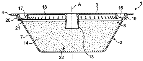
Figure 1 is a perspective view from above of a capsule of the invention;
Figure 2 is a perspective view from below of the capsule of the invention;
Figure 3 is a cross section view of the capsule of the invention;
Figure 4 is perspective view of the capsule with the sealing foil removed;
Figure 5 is a perspective view of the lid from above of the capsule of the
invention;
Figure 6 is a perspective view of the lid from below of the capsule of figure
4;
Figure 7 is a perspective view of the beverage production device of the
invention;
Figure 8 is a perspective view of the beverage production module in open mode;
8
CA 02688378 2009-11-25
WO 2008/148650 PCT/EP2008/056345
Figure 9 is a cross-sectional view along line A-A of the beverage production
module
in a closed mode about the capsule;
Figure 10 is an enlarged view of the view of figure 9;
Figure 11 is a view of the water injection assembly of the module of figures 9
and 10;
Figure 12 is a cross sectional view of a beverage production module similar to
figure
9 but for another embodiment of the invention;
Figure 13 is a detail view of the module of figure 12;
Figure 14 is a cross section view of a variant of the capsule of the
invention;
Figure 15 is a view from underside of the lid of the capsule of figure 14;
Figure 16 is a perspective cross sectional view of a capsule according to
another mode
of the invention;
Figure 17 is a cross sectional view of the capsule of figure 16;
Figure 18 is a cross sectional view of a capsule according to still another
mode.
As shown in figures 1 and 2, a preferred capsule 1 of the invention generally
comprises a dished body 2 onto which is sealed a sealing foi13. The sealing
foi13 is
sealed onto a peripheral rim 4 of the body at a sealing annular portion 5. The
rim 4
can extend outwards forming a small annular portion, e.g., of about 2-5 mm.
The
dished body comprises a bottom wa116 and a side wa117 which preferably widens
in
direction of the large open end of the body opposed to the bottom wall. The
dished
body is preferably rigid or semi-rigid. It can be formed of food grade
plastics, e.g.,
polypropylene, with a gas barrier layer such as EVOH and the like or aluminium
alloy
or a complex of plastic and aluminium alloy. The sealing foi13 can be made of
a
thinner material such as a plastic laminate also including a barrier layer or
aluminium
alloy or a combination of plastic and aluminium alloy. The sealing foil is
usually of a
9
CA 02688378 2009-11-25
WO 2008/148650 PCT/EP2008/056345
thickness between 50 and 250 microns, for example. The sealing foil member can
be
pierced for creating the water inlet and the beverage outlet(s) as will be
described later
in the description.
In relation to the embodiment of figures 3 to 6, the capsule of the invention
comprises
an inner member forming a lid 8 which is inserted in the dished body. The lid
8 and
body 2 delimit together an internal enclosure 14 for receiving the food
substance 22.
Preferably, the capsule forms a symmetry of revolution around a central axis
A.
However, it should be noted that the capsule may not necessarily have a
circular
section around axis A but may take another form such as a square or a
polygonal form.
The lid 8 is illustrated in figures 5 and 6. The lid can take the form of a
disc of plastic
comprising a central portion 9 and a peripheral portion 10. The central
portion can be
substantially flat and may comprise a inlet port 11 for enabling the
introduction of a
water injection member of the beverage production device. In the internal side
12 of
the lid, the inlet port can extend by a tubular inlet portion 13 which serves
for
ensuring the water is guided toward the direction of the bottom of the body to
ensure
complete wetting of the substance in the enclosure and so reduced risk of
leaving for
example "dry powder spots". Preferably, the inlet port is closed by a
breakable or
puncturable closure part 15. This part serves to prevent substance of the
enclosure
from filling the interstice between the upper surface of the lid and the
sealing foil.
The lid further comprises a peripheral portion 10 including a collecting
recess 16. The
collecting recess forms a U-shape in transversal section (figure 3) which
opens in the
direction of the sealing foil. The recess is preferably continuously extending
at the
periphery of the lid although it can be replaced by several discontinuous
recessed
portions which may be separated by reinforcing elements or walls, for example.
The
collecting recess comprises an inner peripheral portion of wall 17 into which
is
provided a series of outlet openings 18 forming a fluid communication between
the
enclosure 14 and the collecting recess 16.
As illustrated in this example, the openings may be slots or holes which are
distributed at intervals in the inner peripheral portion of wall 17. For
example, the
number of slots can range of from 5 to 200, preferably of from 10 to 100.
These slots
have preferably a width that is smaller than the statistical average size of
the particles
of the substance. For example, the slots have a width of less than 600
microns, more
preferably less than 500 microns, most preferably less than 250 microns, for a
substance which is ground coffee. The slots may extend if necessary on the
central
CA 02688378 2009-11-25
WO 2008/148650 PCT/EP2008/056345
portion 9 or in the bottom of the recess 16. The slots can be replaced by
holes of
circular section having a diameter smaller than the statistical average size
of the
particles of the substance.
The collecting recess 16 forms a peripheral groove of small depth, e.g.,
between 2 and
mm to allow the introduction of piercing members through the sealing foil to
produce outlets for the brewed liquid which is produced in the capsule as will
explained later in the description. The collecting recess 16 further comprises
an outer
peripheral portion 19 forming an edge bearing onto a seat portion 20 of the
dished
body. The outer portion 19 can be engaged in the seat portion 20 by a more or
less
tight fit engagement. An additional sealing portion 21 extending along the
internal
surface of the side wall of the body and in the direction of the bottom of the
dished
body can extend from the recess to create further sealing against possible
ingress of
liquid between the lid and the inner surface of the body of the capsule. Of
course, the
form of the collecting recessed means can take different configurations
without
departing from the scope of the invention. For example, the recess 16 can be
formed
by the lid 8 and the side wa117 of the dished body (as illustrated in figure
13). In this
case, the outer peripheral portion 19 can be omitted.
As illustrated in the figures, the series of outlet openings, e.g., slots 18,
are preferably
placed at or close to the widening part of the enclosure relative to the
central axis A.
Therefore, the centrifuged liquid will tend to be guided along the inner
surface of the
side wall of the body, up to the inner side 12 of the lid, and then through
the slots.
The lid 8 is fully closed by the sealing foi13 when it is sealed onto the rim
of the
dished body. In a possible alternative, the sealing foil could cover only the
collecting
recess including the region of the slots.
It should be noticed that the lid 8 can be a rigid or semi-rigid member made
of
thermoformed or injected plastic for instance. However, this part could also
be made
of a flexible membrane which is sealed to the inner surface of the dished body
without
departing from the scope of the invention.
It can also be noticed that a filter wall can also be placed inside the
enclosure against
the inside surface 12 of the lid. A filter wall can provide an improved
filtration, for
example, for substance of very thin particle size or for delaying the release
of the
centrifuged liquid out of the enclosure by creating a higher pressure drop. A
filter wall
can be a paper filter or thin plastic film which is glued onto the surface 12
of the lid.
11
CA 02688378 2009-11-25
WO 2008/148650 PCT/EP2008/056345
The lid can be simply inserted in the dished shaped body or be fixed by any
suitable
connection means such as by ultrasonic welding.
The system including a capsule of the invention and a beverage preparation
device is
illustrated in figures 7 and 8 and described now.
Thus, the system comprises a capsule 1 as aforementioned and a beverage
preparation
device 23. The device has a module 24 into which a capsule can be inserted.
The
capsule contains a food substance for being brewed and the capsule is removed
from
the module after use for being discarded (e.g., for waste or recycling of the
organic
and inorganic raw materials). The module 24 is in fluid communication with a
water
supply such as a water reservoir 25. A fluid transport means such as a pump 26
is
provided in the fluid circuit 27 between the module and the water supply. A
water
heater 28 is further provided to heat water in the fluid circuit before water
enters the
module. The water heater can be inserted in the fluid circuit to heat fresh
water
coming from the reservoir or alternatively can be in the water reservoir that
becomes a
water boiler in such case. Of course, water can also be taken directly from a
domestic
water supply via a water plug connection.
Water can be fed in the module 24 at low pressure or even gravity pressure.
For
example, a pressure of between 0 and 1 bar above atmospheric pressure can be
envisaged at the water inlet of the module. Water at higher pressure than 2
bar could
be delivered if a pressure pump is utilized such a piston pump.
The brewing module 24 can comprise two main capsule encasing sub-assemblies
29,
30; mainly comprising a water injection sub-assembly and a liquid receiving
subassembly. The two assemblies' closes together to encase a capsule therein
for
example by a bayonet-type connection system 31. The liquid receiving
subassembly
30 comprises a liquid duct 32, for example, protruding on a side of the
subassembly
for guiding the centrifuged liquid coming out of the capsule to a service
receptacle
such as a cup or glass. The liquid duct is in communication with a liquid
receiver 33
forming a cylindrical wall placed at a short distance about a rotating drum 34
into
which the capsule is inserted as illustrated in figure 8. The liquid receiver
defines with
the drum an intermediate cavity 63 for collecting the liquid as will be
explained later
in the description. Below the liquid receiving subassembly 30, are placed
means for
driving the capsule receiving drum 34 in rotation inside the subassembly.
The driving means comprise preferably a rotary motor 40 which can be supplied
by
electricity or gas power.
12
CA 02688378 2009-11-25
WO 2008/148650 PCT/EP2008/056345
The water injection subassembly comprises a water inlet side comprising a
water inlet
35 communicating upstream with the water fluid circuit 27.
In relation to figures 9 and 10, the rotary drum 34 is shaped as a hollow
capsule
holder with an internal cavity 36 complementary shaped to receive the capsule.
The
rotary drum 34 prolongs itself axially by a rotating shaft 37 which is
maintained in
rotational relationship relative to an outer base 38 of the liquid receiver 33
by a
rotational guiding means 39 like a ball bearing or needle bearing. Therefore,
the
rotary drum is designed to rotate around a median axis I whereas the outer
base 38 of
the receiver is fixed relative to the device. The liquid receiver 33 can be
fixed to a
housing 43 of the motor by bolts 44 for example. A mechanical coupling 41 is
placed
at the interface between the rotating shaft 37 of the drum and the shaft 42 of
the motor
40.
Considering the water injection subassembly 29, as illustrated in figures 10
and 11, it
comprises a centrally arranged water injector 45 which is fixed relative to
axis I. The
water injector comprises a central tubular member 46 for transporting water
from the
inlet 35 to a water outlet 47 that is intended to protrude inside the
enclosure 14 of the
capsule. The water outlet is formed of a puncturing means 48 such as a sharp
tubular
tip that is able to create a puncture hole through the closing foil of the
capsule and
through the eventual breakable part of the tubular inlet 13 of the lid.
About the water injector is mounted a capsule rotary engaging part 49. The
engaging
part 49 has a central bore for receiving the water injector and rotational
guiding means
such as a ball or needle bearing 50 inserted between the part 49 and the
injector 45.
The engaging part further comprises outlet piercing members 51, 52, 53, 54
protruding from a disc-shaped engaging wa1155 of the part 49. The piercing
members
can be small cylindrical portions with a slanted cutting surface able to cut
or perforate
small holes in the sealing foi13 of the capsule. The piercing members are
arranged at
the periphery of the wa1155, preferably evenly distributed to provide several
openings
in the capsule for the centrifuged liquid to leave the capsule forming several
streams
of liquid.
According to one aspect of the invention, the water injection subassembly 29
further
comprises a valve system 56 for controlling the flow of liquid that is
discharged from
the device. The valve system 56 can be arranged on the capsule rotary engaging
part
49 in the form of an annular engaging portion 57 which is biased under the
force of
elastic loading means 58 such as springs. The annular engaging portion 57
includes a
13
CA 02688378 2009-11-25
WO 2008/148650 PCT/EP2008/056345
pressing peripheral surface 59 which applies a closing force on the peripheral
rim 4 of
the capsule to be able to restrict the flow of liquid under the force of the
elastic
loading means. The surface 59 can form a cone or V for increasing the sealing
pressure in a localized area. The engaging portion 57 further comprises an
internal
base portion 60. The elastic loading means 58 is thus inserted in a space
located
between the base portion 60 and a counter-force portion 61 of the engaging
part 49.
Therefore, at a rest position, the engaging portion 57 of the valve system
keeps
closing on the rim of the capsule under the compressive effect of the
resilient means
58.
The capsule engaging subassembly 29 may further comprise a tubular portion of
skirt
62 which protrudes in the internal annular chamber 63 of the liquid receiving
subassembly 30 when the two subassemblies are closed relatively one another
about a
capsule. This tubular portion of skirt 62 forms an impact wall for the
centrifuged
liquid under pressure that passes through the valve system. This portion 62 is
preferably fixed on the subassembly 29. The subassembly further comprises a
handling portion 64 for facilitating the connection on the liquid receiving
subassembly
30. This handling portion 64 can have a knurled peripheral surface for
handling. The
handling portion can be fixed on the fixed base of the subassembly 29 by
screws 67.
This portion could of course be replaced by a lever mechanism or a similar
handling
means.
As already mentioned, connection means are provided for the relative
connection of
the two subassemblies 29, 30. For example, small pins 65 are provided on the
side of
the tubular surface of the water injection subassembly 29 which can engage
side
locking openings 66 on the tubular surface of the liquid receiving subassembly
30.
Therefore, connection between the two subassemblies can be carried out by a
rotational angular or helicoidal closure movement for enabling the pins to
engage the
oblong openings 66. Of course, other connection means can be envisaged to
replace
this bayonet-type connection means. For instance, a threading means or a
translational
closure means can be envisaged by any person skilled in the art.
The capsule system of the invention works basically according to the following
principle. The capsule device is opened by moving the two subassemblies 29, 30
relatively one another, e.g., by disconnecting the bayonet-type connection and
separating the two subassemblies' 29, 30. As a result, a single-use sealed
capsule 1
containing a food substance can inserted in the device, i.e., placed in the
cavity of the
14
CA 02688378 2009-11-25
WO 2008/148650 PCT/EP2008/056345
rotating drum 36. The capsule can be placed in the device while the capsule
being gas
tightly closed by the sealing foi13. The device is then closed by the
subassembly 29
being connected back onto the subassembly 30 and locked by the connection
means.
In the locked position, the capsule is opened by the water injector that
pierces through
the sealing foil of the capsule and introducing itself through the water inlet
35 of the
capsule. At the same time, several liquid outlets are pierced at the periphery
of the
sealing foil by the outlet piercing members 51-54. Water can thus be
introduced in the
capsule via the central water injector 45. Venting holes can be produced in
the
injection subassemblies to allow gas to escape the capsule while water is
introduced in.
The capsule can be driven in rotation by activating the rotary motor 40. The
start of
the centrifugal operation can be carried out at the same time as water
injection start
being introduced in the capsule or slightly after or before this water
injection
operation starts.
For instance, it might be advantageous for brewing ground coffee, to allow
during
several seconds that water fills in the capsule before starting the
centrifugal operation
by rotating the capsule. Thus, water can properly infiltrate in the coffee
before, the
liquid is centrifuged thereby avoiding coffee area to remain dry in the coffee
portion.
The centrifugation is carried out by rotating the capsule around the central
axis I of
rotation of the device that is preferably aligned to the central axis A of the
capsule.
The rotational speed is preferably of from 1000 to 16000 round-per-metre
(rpm), more
preferably of from 5000 to 10000 rpm. A control unit can be provided in the
device
for setting the rotational speed according to the nature of the liquid to be
brewed
and/or the substance in the capsule. The higher the rotational speed, the
higher the
pressure is exerted at the peripheral wall of the capsule by the liquid and
the more
substance is compacted on the sidewall of the capsule. It is important to
notice that
higher rotational speeds promote brewing of coffee extract containing a lower
solid
content since the residence time of liquid in the coffee bed is lower. Lower
rotational
speeds provide coffee of higher strength since the residence time of liquid in
the
capsule is higher. Brewing takes place in the capsule by water traversing the
substance thereby providing an extraction or partial or total dispersion or
dissolution
of the substance. As a result, a centrifuged liquid is allowed to pass through
the
plurality of outlet openings 18 provided in the capsule, e.g., through the lid
8.
Under the effect of centrifugal forces, the substance, such as coffee powder,
tends to
compact itself radially whereas water is forced to flow through the substance.
This
CA 02688378 2009-11-25
WO 2008/148650 PCT/EP2008/056345
results in the substance being both compacted and intimately wetted by water.
Due to
the high rotational movement of the capsule, the centrifugal forces exert
themselves
uniformly on the mass of the substance. Consequently, the water distribution
is also
more uniform compared to usual methods using a pressure pump to exert the
pressure
in the capsule. As a result, there is less risk of preferential flow path
through the
substance which could lead to areas which are not properly wetted and so not
properly
brewed, dispersed or dissolved. With ground coffee powder, the liquid that
reaches
the internal sidewall of the capsule is a liquid extract. This liquid extract
is then forced
to flow upwards along the internal surface of the sidewall of the capsule.
These outlet openings 18 of the enclosure are sized as a function of the
substance
stored in the capsule. Small openings such as slots of small width or holes of
small
diameter tend to provide a filtering function to retain the solid particles in
the
enclosure of the capsule while allowing only the liquid extract to pass the
openings.
These holes may also form sufficient small restrictions for creating shear
forces and
consequently generating foam or coffee crema. Some gas contained in the
capsule can
become entrapped in the liquid and forms, due to the pressure release after
the
restrictions, a multitude of small bubbles in the liquid. Some significant
shear force of
the centrifuged liquid may also be created at the pierced outlets with the
needles.
The valve system 56 of the device can start opening as pressure of liquid
increases on
the valve when leaving the capsule. Therefore, a certain time delay of the
opening can
be controlled by the valve system to enable sufficient interaction between
water and
the substance contained in the capsule. This controlled delay depends on
various
parameters such as the centrifugal speed, the force exerted by the elastic
loading
means (i.e., spring stiffness), the pressure drop as created by the substance,
outlets, etc.
The opening of the valve system occurs by the pressing surface 59 of the valve
system
lifting as liquid pressure increase on its internal surface. It can be noted
that the
capsule of the rim can also be substantially flexible to flex under the effect
of the
pressure of liquid. Therefore, the relative movement between the pressing
surface and
the capsule create a small passage for the liquid to escape out of the small
interstice
upstream of the valve system. At relatively high rotational speeds, a jet of
liquid can
be formed that impacts on the internal surface of the portion of skirt 62. The
liquid
starts to fill the cavity 68 of the liquid receiving subassembly and liquid
can drain
through the liquid duct 32 to be collected in a cup or glass placed
underneath.
16
CA 02688378 2009-11-25
WO 2008/148650 PCT/EP2008/056345
In the other mode of the invention illustrated in figures 12 and 13, the same
numeral
references have been taken to identify the same or equivalent technical means.
In this
mode, the valve system 56 differs in that the elastic loading means is
obtained by a
rubber elastic 0-ring 69 inserting between a pinching surface 59 and a fixed
portion
61 of the water injection subassembly 29. The 0-ring is maintained between two
concave portions 70, 71 of the valve system. Again during brewing, the
pressure of
liquid in the capsule tends to lift the pinching surface 59 to create a
passage between
the rim 4 of the capsule and the pinching surface. The pinching surface can be
shaped
with a sharp tip that can create a concentration of forces on the rim. Of
course, it
could be imagined that the elastic loading means and the pinching portion are
the
same element. For example, the pinching portion can be made of rubber-elastic
material.
In the mode of figures 12 or 13, the water injector can be a simple water
inlet in the
capsule with no puncture means. In this case, the capsule is pre-opened before
it is
inserted in the device, i.e., the sealing foil is sealed to the rim of the
body by a
peelable sealing to enable the foil to be peeled. Alternatively, a central
hole is
perforated in the foil before the capsule is inserted in the device.
Furthermore, a
water-tight sealing engagement of the water injector can be performed by a
water-
tight sealing means 72 which applies a certain water-tight sealing pressure on
the top
surface of the capsule. Therefore, water is prevented from leaking along the
top
surface of the capsule and from by-passing the capsule to release directly
through the
liquid outlet.
The capsule of the invention can take various embodiments such as the one
illustrated
in figures 14 and 15. The general structure of the capsule is the same as for
the
previous embodiment except that the outlet openings are formed by a filter
paper, a
woven or non-woven portion or another meshed or porous membrane 72. Thus, the
lid
8 which is inserted in the dished body 2 comprises a circumferential band of a
porous
material. The porous material provides restriction of the flow, creating a
certain
pressure drop, e.g., of between 0.5 and 4 bars of relative pressure, and
leading to a
filtering of the solid particles. In particular, the size of the pores of the
material can be
chosen to retain also the coffee fines, i.e., the particles of particle size
as low as 90
microns. The paper, fabric, meshed or porous material can be formed of a band
or
bands which can be welded or otherwise combined to the lid.
17
CA 02688378 2009-11-25
WO 2008/148650 PCT/EP2008/056345
In another possible mode, the recess 16 can be filled by a porous compressible
material to provide a filtering function as well. For example, the material
could be
sponge or fabric.
The system capsule of the invention provide remarkable brewing results with
solid
contents which are higher than with usual systems. The results are very
reproducible
from capsule to capsule. Surprisingly, crema is also remarkably improved with
a
creamier, more stable and thicker texture.
According to figures 16 and 17, the capsule of the invention may also comprise
an
enclosure which is formed of a dished body 2 and a porous wa1180. The dished
body
comprises a main cavity 82 for storing the food substance and a peripheral
recess 81
for receiving the liquid extract that traverses the porous wall 80 during the
centrifugation process. The recess 81 is delimited by an inner edge 83 and an
outer
rim 84 . The porous wa1180 can be attached to an inner edge 83 of the recess
81. A
gastight foil membrane 86 is preferably attached onto the outer rim 84 of the
body.
The inner edge is preferably placed below the outer rim in order to let a free
space 85
between porous wall 80 and the foil membrane 86. The porous wall can be sealed
by
heat or ultrasonic welding onto the inner edge 83.
The porous wall 80 can have openings (i.e., pores) along its whole surface or
along a
peripheral portion of wall only. Figure 16 shows a portion of the wall 87
which
normally have the openings whereas the central portion 88 is free of openings.
In a different mode the two portions 87, 88 have the openings.
The pressure is dependent on various factors, in particular, the rotating
speed of the
capsule in the device, the radius at the peripheral portion of wa1187
(specially,
determining the relative centrifugal force "g" at the portion 87) and the size
of the
openings. The size of the openings is preferably comprised between 1 and 600
microns. More preferably, the size of the openings is comprised between 10 and
200
microns forming a flow restriction means which creates a certain drop of
pressure
during the centrifugation of the capsule along its central axis. The overall
surface area
of the pores of the porous wall should be lower than 50% of the total surface
area of
said wall, most preferably lower than 40%.
The capsule of figures 16 and 17 can be pierced in its centre 89 for injecting
water in
the enclosure 82 containing the substance. As a result both the outer foi186
and the
inner wa1180 are pierced. The capsule is inserted in a device as described
before. The
capsule is driven in centrifugal rotation at a determined speed, e.g., between
1000 and
18
CA 02688378 2009-11-25
WO 2008/148650 PCT/EP2008/056345
16000 rpm, most preferably between 5000 and 12000 rpm. The brewing or
dissolution
process takes place in the enclosure by water traversing the substance. As a
result of
the centrifugal effect, the food liquid traverses the porous portion of
wa1187,
(eventually also part of the portion 88 if porous) and leaves the enclosure
via the
interspace 85 then via the annular recess 81. The liquid is allowed to leave
the capsule
via pierced holes made in the foil above the recess 81.
Figure 18 shows a similar capsule but with the inner porous wa1180 comprising
a
central portion 880 which is sealed to the external gastight foi186 and a
peripheral
portion 870 which is distant from the foi186. In this example, the peripheral
portion
870 comprises the outlet openings of the enclosure. The central portion 880
may have
openings or may be free of openings. In this embodiment, no liquid is allowed
to go
between the outer foi186 and the inner portion of wa11880 since both are
sealed
together. In a variant, a connection member can be inserted between these
parts 880-
86.
It can be noted that the peripheral portion of the capsule comprising the
restriction
means, e.g., openings, can be substantially oriented perpendicularly to the
axis of
rotation as in the examples of figures 16 to 18 or inclined relative to said
axis as in the
example of figures 1 to 6.
If a sufficient pressure drop is created at the portions of wa11870 in the
capsule, the
device may not necessarily be provided with an additional flow restriction
means such
as the valve described previously. In this case, the flow restriction means in
the
capsule suffices to maintain a sufficient pressure in the enclosure and so
obtain a good
interaction between the substance, e.g., ground coffee and water. For example,
good
espresso-type coffee with crema can be produced with a capsule comprising a
woven
polymer membrane comprising pores within a range of between 10 to 200 microns.
In another possible mode, the flow restriction can be obtained or complemented
by
chicanes in the capsule or a similar structure forming a tortuous flow path
for the
liquid.
It can be noted that the pressure drop of the restriction means can be
measured by a
pressure measurement test consisting of filling water under pressure in the
capsule
and measuring the pressure of water at the injection point at which liquid is
allowed to
pass the restriction means, i.e., the valve system.
The term "food liquid" has here a broad meaning and encompasses: a culinary
liquid
such as soup or sauce, a beverage liquid such as coffee (ground and/or
instant),
19
CA 02688378 2009-11-25
WO 2008/148650 PCT/EP2008/056345
chocolate, milk (powder and/or liquid), tea (instant and/or leaf), etc., or a
nutritional
liquid such as an infant formula and combinations thereof.
Of course, the invention may encompass many variants which are included in the
scope of the patent claims that follow.