Note: Descriptions are shown in the official language in which they were submitted.
CA 02688640 2009-12-15
IN THE UNITED STATES PATENT AND TRADEMARK OFFICE
ALEXANDRIA, VIRGINIA
UNITED STATES OF AMERICA
UTILITY PATENT APPLICATION
For
RETRO-FIT LUMINAIRE ASSEMBLY
BY
WILLIAM C. FABBRI, A UNITED STATES CITIZEN, WHOSE RESIDENCE ADDRESS IS
24 HEMLOCK ROAD, BARNSTEAD, NEW HAMPSHIRE 03218
ATTORNEY REFERENCE: ZM098/09158
TECHNICAL FIELD
100011 This invention pertains to troffer luminaires. More specifically,
the
invention pertains to troffer luminaries utilizing retro-fit components which
provide improved optical performance
BACKGROUND
[0002] In certain circumstances during renovation of buildings, labor
intensive
replacement alight fixtures may be limited due to budgetary constraints, while
these buildings may have pre-ekisting luminaire fixtures or housings, typical
renovations provide for removal of the existing lighting and electrical
components, as well as removal of fixture housing structures within the
building.
Removal of the housing requires access above the ceiling level of the building
which may be limited due to the type of ceiling installed, and especially if
the
ceiling is not being replaced.
10003] Complete replacement of lighting fixtures and the components therein
is
quite costly in a renovation budget. Additionally, this labor intensive
activity also
results in high costs for removal and placement of the fixtures.
Png,e 1
CA 02688640 2009-12-15
Title: Retro-Fit Luminaire Assembly
Inventor. William C. Fabbri
Attomey Reference: ZMO98/09158
[0004] In order to limit the costs for lighting in renovation projects, it
would be
highly desirable to utilize certain components or elements of existing
lighting
with retro-fit components in order to improve optical characteristics and
reduce
energy consumption of the lights as well as provide a new look for the
renovation.
[0005] It would also be highly desirable to provide such retro-fit of an
existing
luminaire at a cost which is less than that of a new lighting installation,
both with
respect to the equipment and the labor costs associated therewith.
[0006] When utilizing a pre-existing housing, one issue to overcome is the
length
between lamp sockets in relation to the length of an opening in the ceiling.
Typically, when fluorescent tube lamps are utilized, the length between
opposed
lamp sockets may be greater than a dimensional opening of a suspended grid
ceiling. As a result, it would be highly desirable to overcome this issue in
providing a solution for this and the above deficiencies.
SUMMARY
[0007] A method of retro-fitting an existing luminaire housing comprises
the
steps of removing lighting components from the existing housing, fastening a
first
powertray retaining assembly to an end cap of the existing housing, fastening
a
second power-tray retaining assembly to a second end cap of the existing
troffer,
telescoping a powertray to a size allowing the powertray to be moved through
an
opening in the existing housing, inserting the powertray through the opening
in
the existing housing and retaining the powertray on one of the first and
second
retaining assemblies, telescoping the powertray to engage the other of the
first and
second retaining assemblies and, positioning a diffuser in the troffer. The
method
further comprises connecting a power supply wire to a ballast. The method
further comprises tightening of at least one fastener to lock the powertray at
an
appropriate length once the powertray is engaging the first and second
retaining
Page 2
CA 02688640 2009-12-15
Title: Retro-Fit Luminaire Assembly
Inventor: William C. Fabbri
Attorney Reference: ZM098/09138
assemblies. The method further comprises installing a lamp in lamp sockets on
the powertray.
[0008] A method of retro-fitting an existing luminaire housing, comprises
the
steps of removing lighting components from an existing housing, connecting a
first powertray retaining assembly to the existing housing, connecting a
second
powertray retaining assembly to the existing housing, opposite the first
powertray
retaining assembly, inserting a powertray into the existing housing, extending
the
powertray to a length greater than a distance between support fingers of the
first
and second powertray retaining assemblies, and, mounting a diffuser in the
luminaire housing. The method further comprises tightening a fastener to
maintain the powertray in an extended position. The method further comprises
engaging the diffuser with a spring located on the first and second powertray
retaining assemblies. The method further comprises pivoting the diffuser from
a
first position to a second position.
100091 A method of installing retro-fit components in a pre-existing
housing
comprises positioning a powertray within the pre-existing housing, expanding
the
powertray within the pre-existing housing from a first length to a second
length,
and, positioning a diffuser within the pre-existing housing. The method
further
comprises the step of hanging the powertray from a powertray support assembly
and connecting a power supply wire to one of a ballast or transformer.
[0010] A retro-fit system for a pre-existing troffer luminaire, comprises a
pre-
existing luminaire housing, a powertray having a reflective surface on at
least a
lower side, a ballast on an upper side of said powertray and a plurality of
lamp
sockets positioned near ends of the powertray, the ballast in electronic
communication with the lamp sockets, at least one powertray retaining assembly
disposed near an end of said housing, said powertray retaining assembly
supporting said powertray, the powertray having a first portion and a second
telescoping portion to adjust a length of at least one dimension of the
powertray.
Page 3
CA 02688640 2016-06-08
56146-128
The retro-fit system further comprises a diffuser positioned in a lower
opening of
the pre-existing luminaire housing. The retro-fit system wherein the diffuser
is
pivotable between a first upward position and a second downward position. The
retro-fit system further comprises a release mechanism for downwardly pivoting
the diffuser. The retro-fit system further comprises a diffuser support spring
extending from the powertray retaining assembly. The retro-fit system wherein
the diffuser is a lens.
[0011] A retro-fit system for a pre-existing luminaire troffer, comprises a
light
diffuser moveable between a first position and a second position allowing
access
to an interior of said troffer, a powertray retaining assembly connected to
said
light diffuser and a pre-existing luminaire housing, said powertray having a
ballast and at least one lamp socket electrically connected to the ballast,
the
ballast disposed on an upper side of the powertray, a lower side of the
powertray
being reflective, the powertray retaining assembly comprising at least one
finger
which supports a powcrtray, the powertray having a first portion and an
extendable second portion which allows length adjustment of thc powertray. The
retro-fit system wherein said powertray retaining assembly has a base and at
least
one support arm extending from the base. The retro-fit system wherein the at
least one arm being two support arms. The retro-fit system further comprises a
finger extending from the at least one arm. The retro-fit system wherein the
retro-
fit system has at least one release mechanism. The retro-fit system wherein
the
powertray retaining assembly has a first spring supporting said powertray. The
retro-fit system wherein the light diffuser has a pivot mechanism extending
from
the diffuser and through the retaining assembly.
4
CA 2688640 2017-04-10
81627866
[0011a] According to another aspect, there is provided a method of
retro-fitting an
existing luminaire housing comprising the steps of: removing lighting
components from said
existing housing; fastening a first powertray retaining assembly to an end cap
of said existing
housing; fastening a second powertray retaining assembly to a second end cap
of said existing
housing, wherein said fastened second powertray retaining assembly is
substantially parallel
to the fastened first powertray retaining assembly, thereby defining a
distance between said
powertray retaining assemblies along a line substantially perpendicular to
each of said
powertray retaining assemblies; telescoping a powertray to a size allowing
said powertray to
be moved through an opening in said existing housing; inserting said powertray
through said
opening in said existing housing and retaining said powertray on one of said
first and second
retaining assemblies; telescoping, in a direction substantially parallel to
said line, said
powertray to engage the other of said first and second retaining assemblies;
positioning a
diffuser in said luminaire housing; and, wherein the powertray comprises a
first portion and a
second portion, and each of said telescoping steps comprises sliding the first
portiori against
the second portion.
[0011b] According to another aspect, there is provided a method of
retro-fitting an
existing luminaire housing, comprising the steps of: removing lighting
components from an
existing housing; connecting a first powertray retaining assembly to said
existing housing;
connecting a second powertray retaining assembly to said existing housing,
opposite said first
powertray retaining assembly wherein said connected second powertray retaining
assembly is
substantially parallel to the connected first powertray retaining assembly,
thereby defining a
distance between said powertray retaining assemblies along a line
substantially perpendicular
to each of said powertray retaining assemblies; inserting a powertray into
said existing
housing, said powertray having an adjustable length; extending the length of
said powertray,
in a direction substantially parallel to said line, to a length greater than a
distance between
support fingers of said first and second powertray retaining assemblies; and,
mounting a
diffuser in said luminaire housing.
10011c1 According to another aspect, there is provided a method of
installing retro-fit
components in a pre-existing housing having a directional axis defined by the
longitudinal
4a
CA 2688640 2017-04-10
81627866
direction of lamps to be installed in the housing, the method comprising:
positioning a
powertray within said pre-existing housing; expanding, in a direction
substantially parallel to
the directional axis, said powertray within said pre-existing housing from a
first length to a
second length; and, positioning a diffuser within said pre-existing housing.
[0011d] According to another aspect, there is provided a retro-fit system
for a pre-
existing troffer luminaire, comprising: a pre-existing luminaire housing; a
powertray having a
reflective surface on at least a lower side; a ballast on an upper side of
said powertray and a
plurality of lamp sockets positioned near ends of said powertray, said ballast
in electronic
communication with said lamp sockets; a first and second powertray retaining
assembly
disposed near respective ends of said housing, said first and second powertray
retaining
assembly supporting said powertray, wherein said first powertray retaining
assembly is
substantially parallel to the second powertray retaining assembly, thereby
defining a distance
between said powertray retaining assemblies along a line substantially
perpendicular to each
of said powertray retaining assemblies; said powertray having a first portion
and a second
telescoping portion to adjust a length of at least one dimension of said
powertray in a direction
substantially parallel to said line.
4b
CA 02688640 2009-12-15
Title: Retro-Fit Luminaire Assembly
inventor William C. Fabbri
Attorney Reference: ZM098/09158
BRIEF DESCRIPTION OF THE ILLUSTRATIONS
[0012] Embodiments of the invention are illustrated in the following
illustrations.
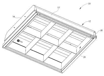
100131 Figure 1 is a lower perspective view of an exemplary retro-fit
troffer
luminaire;
[0014] Figure 2 is a bottom view of the retro-fit troffer luminaire of
Figure 1;
[0015] Figure 3 is an upper exploded perspective view of the internal
components
of the retro-fit troffer luminaire of Figure 1;
[0016] Figure 4 is a lower exploded perspective view of the internal
components
of the retro-fit troffer luminaire;
[0017] Figure 5 is a perspective view of a powertray retaining assembly;
[0018] Figure 6 is a lower perspective view of a diffuser;
[0019] Figure 7 is an exploded side view of the retro-fit components;
[0020] Figure 8 is a lower perspective view of the retro-fit troffer
luminaire in
Figure 7 with a portion of the powertray removed;
[0021] Figure 9 is a detailed perspective view of the powertray retaining
assembly engaging the powertray; and,
[0022] Figure 10 is a lower perspective view of the retro-fit trotTer
luminaire with
the diffuser removed to clearly depict the internal components.
DETAILED DESCRIPTION
[0023] It is to be understood that the invention is not limited in its
application to
the details of construction and the arrangement of components set forth in the
following description or illustrated in the drawings. The invention is capable
of
other embodiments and of being practiced or of being carried out in various
ways.
Also, it is to be understood that the phraseology and terminology used herein
is
for the purpose of description and should not be regarded as limiting. The use
of
Page 5 -
CA 02688640 2009-12-15
Title: Retro-Fit Luminaire Assembly
Inventor: William C. Fabbri
Attorney Reference: ZM098/09158
"including," "comprising," or "having" and variations thereof herein is meant
to
encompass the items listed thereafter and equivalents thereof as well as
additional
items. Unless limited otherwise, the terms "connected," "coupled," and
"mounted," and variations thereof herein are used broadly and encompass direct
and indirect connections, couplings, and mountings. In addition, the terms
"connected" and "coupled" and variations thereof are not restricted to
physical or
mechanical connections or couplings.
[0024] A retro-fit luminaire assembly is shown in the various Figures 1-10.
The
retro-fit luminaire utilizes an exiting housing with older optical and
electrical
components removed and replaces these with universal components which
improve optical performance, reduce energy consumption and are easily
installed.
This system decreases the cost of renovating a building while providing
illumination which looks and performs as a new fixture. The assembly also
decreases labor costs associated with lighting in renovated buildings.
[0025] Referring now to Figure 1, a lower perspective view of a retro-fit
troffer
luminaire assembly 10 is depicted. The retro-fit troffer luminaire 10 includes
a
housing 12 which may be pre-existing in a building or other structure being
renovated. The original lighting components originally installed in the
original
luminaire 10 are removed and are replaced with these retro-fit components 11
(Figure 3) described herein, so as to provide a retro-fit light assembly
having a
new look and optimal lighting characteristics without the costs of a
completely
new fixture and labor involved with such installation. This is advantageous
for
consumers. The use of the existing housing 12 in combination with the ease of
installation of the components 11 can decrease the installation time for each
retro-
fit troffer luminaire 10 to about fifteen minutes or less. This is
advantageous for
consumers.
[0026] The housing 12 as shown in Figures 1, 8 and 9 has a body defined by
a
generally flat upper surface 13 and two depending sidewall surfaces 14, 15
which
Page 6
CA 02688640 2009-12-15
Title: Retro-Fit Luminaire Assembly
Inventor: William C. Fabbri
Attorney Reference: ZM098/09158
are adjoined to the upper surface 13 so that the housing 12 is generally
parabolic
in shape. Such construction is not required as other shapes may be utilized,
and
therefore the instant housing construction should not be considered limiting
but
merely exemplary. The housing 12 further comprises a first end cap 16 and a
second end cap 18 which are positioned at ends of the housing 12 to generally
close the housing structure. Each of the first and second end caps 16, 18
engage
the end edges of the housing top wall 13 and sidewalls 14, 15. Thus, the end
caps
16, 18 are shaped similarly to the end profile of the housing 12 in order to
receive
the ends of the body portion of the housing.
100271 The housing 12 generally define a lower opening of the troffer
luminaire
wherein a diffuser 20 is positioned. The term diffuser should be understood to
mean any structure which varies the light output of the lamp within the
luminaire
10. For instance, the diffuser 20 could be a louver arrangement, as depicted,
or it
could be a lens, shielding or any other structure as defined. Thus, the
exemplary
louver shown should not be considered to limit the term diffuser. The diffuser
20
may have a reflective surface which is specular or diffuse and may be formed
of
metal, polycarbonate or other materials which may or may not be coated. The
diffuser could also be a door frame with a lens. The diffuser 20 may be
defined
by a new component which is retro-fit into the existing housing or may be an
existing diffuser which is utilized after the internal optical and power
components
are installed into the housing 12. The exemplary louver may be a multi-cell as
described further, depending on the dimensions of the housing, with a
reflective
white outer coating on at least the visible surfaces thereof
100281 Installing the retro-fit component 11 (Figure 3) is less costly than
complete replacement with a new lighting fixture. Since the existing housing
12
is utilized, the internal optical and power components of the pre-existing
luminaire need only be removed. Subsequently, the new components are installed
into the existing housing which therefore does not require access above the
ceiling
Page
CA 02688640 2009-12-15
Title: Retro-Fit Luminaire Assembly
Inventor: William C. Fabbri
Attorney Reference: ZM098/09158
where the luminaire 10 is positioned. Thus, since the housing is not replaced
and
since existing power supply wiring is used to power the lighting components,
less
labor is utilized in installing the retro-fit luminaire 10. One limiting
factor of the
retro-fit factor component is the size of the housing 12. As described further
herein, the retro-fit components compensate for varying dimension of the
original
housing thereby providing an assembly usable with various housings.
[0029] Referring now to Figure 2, a bottom view of the retro-fit troffer
luminaire
is depicted. The diffuser 20 is fitted within the opening defined by the
housing
12 and end caps 16, 18. Within the housing 12 above the diffuser 20 is a
powertray 30. Positioned between the powertray 30 and the diffuser 20 is at
least
one lamp 26. The exemplary lamp may be a fluorescent lamp although other
lamp types may be utilized. For example, the fluorescent lamp may be a T5, a
T8,
a TT5 or a T5H0. The lamp 26 may be limited by the size of the housing such as
2X2, 2X4 or 1X4, for example, and the amount of light output desired for the
area
be illuminated. Additionally, other light sources and types may be utilized in
order to provide a desirable light output and therefore this description
should not
be considered limiting.
[0030] As described above, one limiting factor for use of the retro-fit
components
is the size of housing 12. The bottom view of Figure 2 depicts at least one
fastener 35 which allows slidable adjustment of at least one dimension of the
powertray 30. A slot 37 allows adjustment in the direction of the slot (right
and
left in figure) to lengthen or shorter the powertray 30. As discussed
previously,
an opening in a suspended ceiling grid typically has a dimension which is less
than a corresponding dimension between lamp sockets. For example, for
luminaires having 48" (inches) lamps, a corresponding opening dimension of a
suspended ceiling is typically 47" (inches). The powertray 30 therefore must
be
able to fit within the opening defined by the suspended ceiling grid and
housing
opening, but also expand to a size capable of use with the appropriate lamp
Page 8
CA 02688640 2009-12-15
Title: Retro-Fit Luminaire Assembly
Inventor: William C. Fabbri
Attorney Reference: ZMO98/09158
length. The slot 37, in combination with the first and second portions of the
powertray 30 allow the lengthening or shortening of at least one powertray
dimension so that the powertray 30 can fit through the ceiling grid opening as
well as position lamp sockets 40 at an appropriate distance for use with
lamps.
[0031] Referring now to Figure 3, an exploded perspective view of the
optical
and power retro-fit components 11 is depicted with the housing 12 removed. The
powertray 30 includes a first portion 32 and a second slidable portion 34. The
second portion 34 is extendable or telescoping in order to adjust the length
dimension of the powertray 30 for various sizes of pre-existing housings 12.
As
described previously, the powertray 30 allows for positioning through the
smaller
housing and grid ceiling opening, while allowing expansion to accommodate
proper spacing of the lamp sockets 40. The powertray 30 includes an upper
surface 36 and a lower surface 38 (Figure 2). The lower surface 38 of the
powertray may be a reflective material, such as a ninety five percent
reflective
white baked polyester enamel over a dye formed cold rolled steel. It could
also be
alternative reflective finishes or materials. The steel or other metallic
material
may have a preventative rust undercoating as well.
100321 Also positioned on the upper surface of the powertray 30 is a power
supply, transformer or ballast 38. The power supply receives an input power
connection from existing wiring in the housing 12 (Figure 1) and is in
electrical
communication with a plurality of lamp sockets 40. According to the exemplary
embodiment, the ballast 39 has input wiring 39a for receiving power to
energize
the lighting components as well as wiring 39b extending from the ballast 39 to
a
plurality of lamp sockets 40. These sockets 40 connect to the at least one
lamp
26. According to the exemplary embodiment, four lamp sockets 40 are utilized
to
power two lamps 26. The powertray 30 may be prewired to further aid in fast
installation and therefore reduced installation costs.
Page 9
CA 02688640 2009-12-15
Title: Retro-Fit Luminaire Assembly
Inventor: William C. Fabbri
Attorney Reference: ZM098/09158
[0033] Adjacent the powertray 30 at housing ends corresponding to end caps
16,
18 locations are first and second power tray retaining assemblies 50. The
powertray retaining assemblies 50 each connect to the end caps 16, 18 (Figure
1)
and support the powertray 30 at each end thereof The powertray retaining
assemblies 50 are fastened against end caps 16, 18 thus limiting the powertray
30
length to the corresponding length between the end caps 16, 18 or the
corresponding length of the body of the housing 12 or ceiling grid opening.
[0034] Referring now to Figure 4, a lower perspective view of the retro-fit
components 11 including the powertray 30, the retaining assemblies 50 and the
diffuser 20 are depicted. The lower surface 38 of the powertray 30 is formed
of a
reflective material to increase optical performance of the retro-fit luminaire
10.
The powertray 30 has a gull-wing or bat-wing shape to receive first and second
lamps 26. Alternatively, other reflector shapes could be utilized. The
powertray
retaining assemblies 50 each have first and second arms 60, 62 supporting each
end of the powertray 30.
100351 From the lower view of the powertray 30, the fasteners 35 are
depicted.
These fasteners 35, according to the exemplary embodiment, are thumbscrews
which allow tightening of the first portion 32 against the second portion 34.
The
fasteners 35 are also coated with a reflective material to enhance optical
characteristics of the powertray 30 and inhibit creation of dark spots within
the
luminaire. The powertray 30 is extended to a size which allows the powertray
30
to be supported by each of the retaining assemblies. Subsequently, the
fasteners
35 are tightened.
[0036] Referring now to Figure 5, a powertray retaining assembly 50 is
depicted
in perspective view. The powertray retaining assembly 50 includes a base
portion
52 which is defined by, for example, an extruded shape or structure. The base
portion 52 has a first generally horizontal leg 54 and a first vertical leg 56
connected thereto. This defines a generally right angled structure. At the
upper
Pape 10
CA 02688640 2009-12-15
Title: Retro-Fit Luminaire Assembly
Inventor: William C. Fabbri
Attorney Reference: ZMO9S/09158
portion of second leg 56 a second right angled structure is defined by a
second
horizontal leg 57 and an upper second vertical leg 58.
[0037] Extending from the base portion 52 are the first and second
powertray
support arms 60, 62. Each of the first and second support arms 60, 62 has a
lower
vertical structure 63, a lower horizontal structure 64 extending in an outward
direction relative to the housing 12, a second vertical structure 65 and a
second
horizontal structure 66 extending inwardly relative to the housing 12. Each of
the
second vertical structures includes a fastening aperture 67 These apertures 67
are
utilized in combination with a fastener to attach the powertray retaining
assembly
50 to the end caps 16, 18. The upper horizontal structures 66 provide support
for
the powertray 30 when the luminaire 10 is constructed.
[0038] The powertray assembly further comprises a spring 70 which provides
a
seat for an upper lip area of a diffuser 20. The spring shoulder 72 receives
an
upper lip portion of the diffuser 20 when the diffuser is positioned in the
fixture
10. The spring 70 may be pulled away from the diffuser so that the shoulder 72
no longer supports the upper lip portion of the diffuser 20 and allows for the
diffuser 20 to drop downwardly.
[0039] The housing 12 (Figure 1) has a height which limits the height of
the
retaining assembly 50. The height of the retaining assembly 50 should be less
than or nearly equal to the height of the housing to inhibit any portion of
the
components from extending below the ceiling level. The height of the exemplary
assembly 50 requires a housing to have a height of at least about 4-3/8
inches.
However, this dimensional description is merely exemplary and should not be
considered limiting.
100401 The powertray retaining assembly 50 also includes a tab 55 which
extends
at an angle from the upper vertical leg 58. The tab 55 is utilized to hang the
powertray 30 therefrom so that the wiring connections may be made between the
power input wire and that transformer or ballast 39. As shown in Figure 3, the
Page 11
CA 02688640 2009-12-15
Title: Retro-Fit Luminaire Assembly
Inventor: William C. Fabbri
Attorney Reference: ZM098/09158
powertray 30 includes a slot 33 which receives the tab 55. When the tab 55 is
positioned through the slot 33, the powertray 33 is fully supported in a
hanging
position from the assembly 50. In this position, the installer can work "hands-
free" meaning that the installer does not have to hold the powertray 30 with
one
or both hands. Instead, the installer can focus on the wiring installation
with both
hands.
[0041] The base portion 52 has a slot 59a at one end and an aperture 59b at
the
other end. The slot 59a is utilized for allowing pivoting and installation of
the
diffuser 20. The aperture 59b receives an opposite end of the diffuser 20 when
the diffuser is rotated upwardly and is seated on spring 70.
[0042] Referring now to Figure 6, a diffuser 20 is depicted in a lower
perspective
view. In the embodiment depicted, the diffuser 20 is a louver which is
generally
square in shape. The shape of the diffuser 20 is limited by the shape of the
housing opening. The diffuser 20 has a plurality of louver blades 22 to define
cells 23 in the structure. The diffuser 20 includes an outer frame defined by
a
plurality of frame structures 21. Within the frame are a plurality of louver
blades
22. The diffuser 25 also includes hinge pins 25 which are received by the base
portions 52 of the powertray support assembly 50, specifically slot and
aperture
59a, 59b. As previously described, the diffuser 20 may alternatively be
embodied
by a lens or other structure. Additionally, the structures providing pivoting
connection between the diffuser 20 and the powertray support assembly 50 may
differ but should be considered within the scope of the present embodiment as
various designs may be utilized to ease installation and maintenance.
[0043] Referring now to Figure 7, an exploded side view of the retro-fit
components 11 is depicted. The powertray 30 is shown being supported by the
powertray retaining assembly 50 and specifically the support arms 60, 62
thereof
The diffuser 20 is shown beneath the powertray retaining assembly 50 and may
be
moved upwardly to engage the powertray retaining assembly and may be seated
Page 12
CA 02688640 2009-12-15
Title: Retro-Fit Luminaire Assembly
Inventor: William C. Fabbri
Attorney Reference: ZM098/09158
within pivot apertures 59. The diffuser 20 includes projections 26 which are
received by the pivot apertures 59 to retain the diffuser 20 therein.
[0044] Additionally, Figure 7 shows how the second horizontal structures 66
of
the support arms 60, 62 support the powertray 50 from the below. Thus, the
retaining assembly 50 is at least partially supported by a suspended ceiling
through attachment to the end caps 16, 18 (Figure 2). The assembly 50 can
therefore support the powertray 30 as well.
10045] Referring now to Figures 8 and 9, the wiring connections may be seen
within the retro-fit luminaires. With the powertray 30 partially removed in
Figure
9, the ballast 39 is shown floating beneath the housing top wall 13. The
ballast
39, as previously described, is connected to the powertray portion which is
removed. Extending from the ballast 39 are wiring elements extending to the
sockets 40. The first and second lamps 26 extend between pairs of sockets 40
providing the electrical components for the retro-fit luminaire 10. Power
extends
into the housing 10 from existing wiring (not shown) and supplies the ballast
39
with the requisite voltage and current needed to power the system. The ballast
39
may be a line voltage or a variable input voltage ballast depending on the
types of
lamps utilized in the system.
[0046] Referring now to Figure 10, a lower perspective view of the retro-
fit
luminaire 10 is depicted. The retro-fit components 11 (Figure 7) are disposed
within the pre-existing housing 12. The lower opening defined by the housing
12
and the powertray retaining assemblies 50 allow for positioning of a diffuser
(not
shown) beneath the lamps 26 and the powertray 30.
[0047] For installation, the original electrical and optical components are
removed from the housing 12 and the powertray retaining assemblies 50 are
fastened into the end caps 16, 18 through the support arms 60, 62. The
powertray
30 is supported on the powertray retaining assembly 50 by connection of slot
33
with tab 55. Next, the input power wire is connected to the ballast or
transformer
Page 13
CA 02688640 2009-12-15
Title: Retro-Fit Luminaire Assembly
Inventor: William C. Fabbri
Attorney Reference: ZM098/09158
39. With the retaining assemblies 50 positioned in the housing 12, the
powertray
30, with the sockets 40 and wiring connections 39b complete, is inserted into
the
housing 12. In order to accomplish this, the fasteners 35 are loosened and the
powertray second portion 32 is shortened to a length which is less than the
distance between the support arms 60, 62. One end of the powertray 30 lifted
upwardly above a first powertray retaining assembly 50, and the second end of
the
powertray is lifted above the second powertray retaining assembly 50 and above
the second horizontal support arms 56 (Figure 5). Once the powertray 30 is
entirely positioned in an elevation above the retaining assemblies 50, the
second
portion 32 is slidably extended or telescoped outwardly to a distance greater
than
the inner distance between the second, upper support arms or fingers 66 on
each
side of the luminaire 10. Thus, the powertray is supported by the retaining
= assemblies 50 within the housing. Next, the lamps 26 may be connected to
the
sockets 40. Finally, the diffuser 20 is lifted upwardly into the opening
defined by
the housing 12 and the retaining assemblies 50. The diffuser 20 may be
pivotally
connected provided for easier handling by a single installer, as previously
described.
[0048] The foregoing description of several embodiments of the
invention has
been presented for purposes of illustration. It is not intended to be
exhaustive or
to limit the invention to the precise steps and/or forms disclosed, and
obviously
many modifications and variations are possible in light of the above teaching.
It
is intended that the scope of the invention and all equivalents be defined by
the
claims appended hereto.
Page 14