Note: Descriptions are shown in the official language in which they were submitted.
CA 02688809 2009-12-15
1
Toilet bowl with flush flow control
The present invention refers to horizontal toilet bowls with
control of the flow of the flush by means of an electric pump system, solenoid
valves for
flow control and an electronic device.
State of the Art
The first devices used by human beings to discharge human
waste, such as urine, feces and others, were created as soon as the first
large-scale
human settlements were formed.
Until the mid-19th century, the main devices used for this
purpose had seats with holes directly conducting the excrement to sewers and
sinkholes
directly excavated in the soil.
With the advent of forced water conduction systems, more
efficient devices for this purpose had to be created, especially due to the
verticalization of
human settlements in general.
Created in England by the end of the 19th century under the
name of water closet, toilet bowls, together with water and sewer facilities
in buildings,
constituted a technological improvement, allowing human beings to improve
sanitary
conditions in urban centers, thus improving the population's quality of life.
Toilet bowls are anatomic receptacles provided with a given
quantity of water intended to receive human bodily wastes (urine, feces, etc.)
and an
internal device to remove them by means of a water flow.
The flow of water is generally provided by a flushing device
that supplies the toilet bowl with water in appropriate volume and speed not
only to
remove the matter in the bowl, but also to horizontally push it through the
sewage tubes to
' the vertical tube of the building facility.
Toilet bowls may be configured to work by the principles of
siphoning or dragging.
a. Toilet bowls with siphoning action
In toilet bowls with siphoning action, flush water is introduced
into the bowl by means of a distribution collar located at the upper part of
the bowl.
Guided by the sloping of the bowl walls, the flow of water converges to the
bottom of the
bowl. The resulting hydrodynamic energy of the volume and flow of the flush
moves the
mass constituted by the liquids and solids deposited inside the bowl, sending
them to the
siphon located inside the bowl.
The siphoning process pushes the contents off the bowl
through the sewer pipes located below the floor.
For bowls with siphoning action to be effective with reduced
volumes of water, the size of the water well inside the bowl and the diameter
of the siphon
CA 02688809 2009-12-15
2
,must be reduced. By reducing the size of the siphon, the capacity of the bowl
to let larger
solid waste go through is directly reduced, with the consequent increase in
the risk of
undesirable clogging.
Low consumption toilet bowls with siphoning action coupled
to flush tanks with reduced flow (1.4 I/sec) work near the limits of use by
frequently leaving
annoying disposed matter after the flushing, thus requiring a second flushing
to fully clean
the bowl
For this kind of bowl to work appropriately, water must be
supplied by a flush tank located in a higher position, able to supply a flow
of at least 1.7
I/sec.
b.' Drag toilet bowls:
In this kind of bowl, the bodily waste is directly expelled from
the bowl well to the sewage system by means of a large diameter pipe, which
allows the
free passage of the mass of liquid and solid waste, independently of their
nature, volume
or density.
The transfer of the waste from the toilet well to the
drainpipes is solely made by the hydrodynamic energy coming from the water
flush
applied in the process.
For this kind of bowl to work efficiently, the speed of the
water must be between 1.7 and 2.2 liters per second. The higher the pressure
of the flow,
the larger the capacity of solid removal from the well of the bowl. The higher
pressure of
the flow, the better the horizontal flow of sewage to the vertical pipe and
the better the
general performance of the system.
Drag toilet bowls with low consumption (6 liters) should
therefore be coupled to cisterns installed in a high position to provide high
flow flushes
(1.7 to 2.2 Usec) (source: http://www.f6rumdaconstrucao.com.br
/conteudo.php?a=24&Cod=39). Both kinds of bowls require a reasonable volume of
water
to fully drag the waste material in them.
Since water is a limited natural resource (less.than 2% of the
all the water on the planet is available for immediate use by human beings),
we verified
the need to reduce the water consumption of flush toilets.
International rules, such as the European rule and the
Brazilian rule; have been adapted to this reality, more and more requiring
that the water
volumes used in the flush devices be reduced and controlled.
The need to control and reduce the volume of water used in
flush toilets practically eliminated the possibility of use of direct flush
valves such as the
ones used in the recent past. Various flush devices have been created through
time to
CA 02688809 2009-12-15
3
control the flush in order to maximize their efficiency with the lowest
possible volume of
water.,
Among these devices, we highlight electric pump assisted
devices, especially in drag toilet bowls, to maximize efficiency with the
lowest possible
volume of water.
Various enhancements have been proposed.. As an
example, US patents US 5926863 and US 2007277302 improve the drag system by
using
parallel systems to better adequate the flow of water. Other enhancements
proposed are
the American patent US 4918764 and the Brazilian patent MU 7200798-2 that try
to
improve the flush by means of electric flushing devices.
The author of the present application also owns various
patent applications in this field, including Brazilian patent application MU
8601167-7,
which has an electronic water flush control set.
All applications and/or patents mentioned here as examples
present some specific problem. Such applications and/or patents do not provide
a
continuous and efficient flush, or they do not provide a minimum flush volume,
or they
cause discomfort to users by sprinkling used water when flushed, spreading
germs in the
environment.
Summary of the Invention
The object of the present invention is to present a flushing
system that ensures full control of the water flow used in the flush, with a
minimum volume
of water, without causing inconveniences such as sprinkling during the
flushing process.
Said objective is reached by a system constituted of a bowl
provided with an electric pump and valve set that control the volume of water
efficiently,
being said bowl provided with specific geometry that uses said water flow more
effectively,
without causing the dispersion of infecting droplets in the ambient.
Furthermore, the present invention is provided with a system
that controls the flow of water used, since it has two stages of water
flushes, a first one
with lower volume for liquid excrement and a second one for solid excrement.
Description of Drawings
The present utility model application will be better
understood in the light of the attached figures, shown here as mere examples,
without
limiting the scope of the present invention, wherein:
- Figure 1 is an upper view of a toilet bowl of the state of the art;
- Figure 2 is a section view of the proposed bowl with valves and electric
pump;
- Figure 3 is an upper view of the proposed bowl with valves and electric
pump; and
- Figure 4 is an upper view of an alternative of the proposed bowl with valves
and electric
pump.
CA 02688809 2009-12-15
4
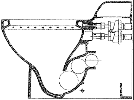
Description of a Main Embodiment
The present utility model will be disclosed based on the
attached figures, wherein letter A shows the toilet bowl set including a
toilet bowl (100), a
set of valves (200) and an electric pump (300).
The bowl (100) has an upper rim or "ring" (101) through
which a part of the full volume of water required for each flushing operation
in the bowl is
injected. In the direction of the ring (101), there is a duct (102) through
which said partial
volume of water is injected. In the well (103), there is a second injection
duct (104)
through which another part of the volume of water required for a flushing
procedure is
injected. At the bottom of the well (103), there is a hole (105) that
communicates with the
passage duct (106) which, on the other hand, is connected to the sewer network
(not
shown). The passage duct (106) has such geometry that its initial section
(106a) is longer
than the final section (106b), generating a duct with Venturi characteristics,
speeding up
the movement of the water and therefore facilitating the full flush of the
water injected in
the well (103).
Coupled to the bowl (100), there is the set of valves (200),
constituted of an upper valve (201) and a lower valve (202). The upper valve
(201) has an
outlet which is coupled to the duct (102), while the lower valve (202) is
coupled to the duct
(104).
The set of valves (200) is fed by an electric pump (300)
which may or may not be immersed in a flush tank (Figures 3 and 4). The set of
valves
(200) and pump (300) is controlled by an electronic system (not shown), e. g.
a double
solenoid electrical diaphragm valve, which allows the electric pump (300) to
feed only one
valve or the other (201, 202) or both valves simultaneously.
The operation of the system is simple and consists of the
actuation of the flush by the electric valve. After its operation is started:
1. the upper valve (201) opens and the electric pump (300) sucks the water
directed by
the duct (102) in enough volume to clean the ring (101) and inside the well
(103);
2. the upper valve (201) closes, while the lower valve (202) opens, and
through the duct
(104), directs the water to the well (103) by the duct (104), and this volume
causes the exit
of the excrement through the hole (105) which communicates with the duct (106)
that
takes the excrement out of the bowl (100); and
3. the lower valve (202) closes and the water is again re-directed to the
upper valve (201),
forcing the water through the ring again (101) and recomposes the water seal
of the bowl
(100).
Optionally, if the water network supply is reliable, the flush
tank coupled to the toilet bowl may be excluded. The electric pump receives
the water
directly from the pre-installed supply network. In this case, the electric
pump should have
CA 02688809 2009-12-15
inlet and outlet pipes in such dimensions that the pump will not work dry,
having uniform
pressure along the process.
The present invention is highly efficient in the limitation of the
water used in the flushing process, and is also more hygienic, since:
5 - it has an electric pump and valves that make better use of the supplied
water;
- it works in alternate cycles, which controls the volume of water that
arrives at once at the
well of the bowl, thus avoiding the water to spread; and
- it is more hygienic due to its several washing steps.