Note: Descriptions are shown in the official language in which they were submitted.
CA 02688810 2010-01-06
BE-22814-CA
1
Dispensing device for milk and/or milk foam and a coffee
machine comprising such a dispensing device
The invention relates to a dispensing device for milk and/or
milk foam and a coffee machine comprising such a dispensing
device.
In known dispensing devices for milk and/or milk foam,
usually milk is mixed with steam (in particular water
vapour) and possibly air, in order to produce heated milk or
milk foam and/or a mixture of heated milk and milk foam.
Such dispensing devices are frequently also integrated in
coffee machines, particularly as coffee machines generally
also comprise a device for producing water vapour. Coffee
machines comprising an integrated dispensing device for milk
and/or milk foam in the known manner make it possible to
produce either coffee (without the addition of milk) or
heated milk (without the addition of coffee) or white coffee
(without the addition of milk foam) or speciality coffees,
which contain milk foam or foamed milk (for example
cappuccino or latte macchiato).
In dispensing devices for milk and/or milk foam, which are
used in combination with coffee machines, generally a vacuum
is produced ("Venturi effect") by a jet of steam in a
suitably shaped nozzle ("Venturi nozzle") which makes it
possible to suck from a reservoir (milk container) filled
with milk a portion of milk via a line between the nozzle
and the reservoir and to conduct said portion of milk into
the nozzle. In order to produce heated milk only (without
milk foam), the suctioned milk may be mixed in a chamber of
the respective dispensing device with the steam injected
into the nozzle and, as a result, heated. Subsequently, the
CA 02688810 2010-01-06
BE-22814-CA
2
milk-steam-mixture thus produced may be dispensed in the
form of a steady output jet from the dispensing device via
an outlet into a suitable receptacle. In order to produce
milk foam and/or foamed milk, additional air may be
suctioned with the steam jet (for example via a continuous
line for the ambient air) and mixed in the chamber with the
respective suctioned milk. In this variant, a milk-steam-air
mixture in the form of a steady output jet may be dispensed
from the chamber via the outlet into a suitable receptacle,
in this case a mixture of heated milk and milk foam being
collected in the receptacle.
Hitherto, a plurality of dispensing devices for milk and/or
milk foam of the aforementioned type, based on a mixture of
milk, steam and air have been proposed, which permit a user
to produce milk and/or milk foam in different variants.
For example, a dispensing device for producing milk foam is
known from EP 1 115 317 Bl, in which a flow of the milk
respectively suctioned by a steam jet with a valve which is
arranged in a line for supplying milk and which comprises a
manually adjustable regulating shaft for regulating a supply
of milk, may be preselected by a manual adjustment of the
regulating shaft and/or altered by a manual adjustment of
the regulating shaft. In the present case, the regulating
shaft is an adjustable body with a through-hole for the
milk. By a suitable adjustment of the regulating shaft a
user may influence and/or limit the quantity of milk
suctioned by means of a steam jet. The air respectively
suctioned and mixed with the milk may not be specifically
influenced in this dispensing device. This dispensing device
has the drawback that the possibility of producing different
types of milk and/or milk foam is limited. As only the
CA 02688810 2010-01-06
BE-22814-CA
3
quantity of suctioned milk may be altered by adjusting the
regulating shaft, a user is only able to foam milk with this
dispensing device and thus at best influence the quantity
and the temperature of the milk foam produced and/or the
mixture of heated milk and milk foam produced. A use of this
dispensing device in combination with a coffee machine is,
therefore, extremely awkward for a user with regard to the
production of speciality coffees, which are based on a
combination of coffee, milk and/or milk foam, particularly
because before producing a specific coffee speciality the
user firstly has to determine by experimentation the optimal
setting of the regulating shaft of the valve which
corresponds to the wishes of the user. Several attempts at
this are generally necessary. In this connection, it is a
drawback that a manual adjustment of the regulating shaft is
generally time-consuming and only able to be duplicated
inaccurately. It is, therefore, difficult for a user to
produce different types of milk foam and/or a mixture of
heated milk and milk foam and/or different types of
speciality coffees.
A dispensing device based on a mixture of milk, steam and
air for producing milk foam and heated milk is also known
from EP 1 688 074 Bl, in which an inlet opening for air in a
line for supplying air comprising a valve for controlling
the air supply may be selectively opened or closed. A
closure body of the valve may be moved by means of an
electric motor, in order selectively to open the valve by
activating the electric motor and in this manner to permit
the supply of air or to close the valve and in this manner
to prevent the supply of air. The dispensing device further
comprises a line for the supply of milk, a user having no
possibility of regulating (i.e. switching off, switching on
CA 02688810 2010-08-23
'25943-32(S)
4
and/or varying) a flow of milk through this line. In this
dispensing device, therefore, a user may suck a
predetermined quantity of milk with a steam jet and at the
same time mix the suctioned air either with the steam and a
predetermined quantity of air (provided the valve is opened
for controlling the air supply) or simply mix with the steam
(provided the valve is closed for controlling the air
supply). In this dispensing device, by actuating the valve a
user only has the possibility of producing two different
types of milk beverages: a predetermined quantity of heated
milk without a proportion of milk foam (with the valve
closed) or a predetermined quantity of foamed milk with a
predetermined consistency (with the valve open). This
dispensing device also has the drawback, therefore, that the
possibility of producing different types of milk and/or milk
foam is limited. In combination with a coffee machine,
therefore, this dispensing device also provides a user with
little freedom of choice when producing speciality coffees,
which are based on a combination of coffee, milk and/or milk
foam.
CA 02688810 2010-08-23
25943-32(S)
4a
The object of some embodiments of the present invention is to avoid
the aforementioned drawbacks and to provide a dispensing device for milk
and/or
milk foam, which is able to produce repeatedly a large number of different
types of
milk beverages based on milk and/or milk foam in a simple manner with
predetermined properties in each case and of predetermined quality in each
case,
in a reproducible manner. The dispensing device is also intended to be able to
be
used in combination with a coffee machine.
According to an aspect of the invention, there is provided a
dispensing device comprising: a mixing device, comprising; a chamber; a first
line
configured to supply milk into the chamber; a second line configured to supply
steam into the chamber; a third line configured to supply air into the
chamber; at
least one outlet for dispensing at least one of milk and milk foam from the
chamber; and a valve comprising an adjustable regulating shaft, wherein the
valve
is configured to regulate the supply of at least one of milk and air into the
chamber
by adjusting the regulating shaft between different predetermined positions,
one of
the different predetermined positions configured to switch on or off or alter
a flow
of milk or air; a drive motor configured to adjust the regulating shaft of the
valve of
the mixing device; and a control device configured to control the drive motor
and
thereby configured to control the movement of the regulating shaft into the
respective predetermined positions.
According to another aspect of the invention, there is provided a
coffee machine, comprising: a coffee outlet head configured to dispense a
coffee
beverage; and a dispensing device, comprising: a mixing device, comprising: a
chamber; a first line configured to supply milk into the chamber; a second
line
configured to supply steam into the chamber; a third line configured to supply
air
into the chamber; at least one outlet for dispensing at least one of milk and
milk
foam from the chamber; and a valve comprising an adjustable regulating shaft,
wherein the valve is configured to regulate the supply of at least one of milk
and
air into the chamber by adjusting the regulating shaft between different
predetermined positions, one of the different predetermined positions
configured
CA 02688810 2010-08-23
'25943-32(S)
4b
to switch on or off or alter a flow of milk or air; a drive motor configured
to adjust
the regulating shaft of the valve of the mixing device; and a control device
configured to control the drive motor and thereby configured to control the
movement of the regulating shaft into the respective predetermined positions.
CA 02688810 2010-01-06
BE-22814-CA
This dispensing device comprises a mixing device for mixing
steam, milk and/or air, which mixing device comprises: a
chamber, a first line for the supply of milk into the
5 chamber, a second line for the supply of steam into the
chamber, a third line for the supply of air into the
chamber, at least one outlet for dispensing the milk and/or
the milk foam from the chamber and a valve comprising an
adjustable regulating shaft for regulating the supply of
milk and/or air into the chamber, by adjusting the
regulating shaft between different predetermined positions
at least one flow of milk being able to be switched on and
switched off and/or altered and a flow of air being able to
be switched on and switched off and/or altered.
Via the first line, the second line and the third line,
accordingly milk, steam and possibly air may be supplied
into the chamber, so that milk, steam and possibly air may
form a mixture in the chamber.
The chamber may, for example, also be configured as a
"vacuum chamber". The term "vacuum chamber" is understood in
this context to be a chamber in which, by the supply of
steam into the aforementioned chamber, a pressure may be
produced which is lower than the pressure in the first line
and/or the pressure in the second line and/or the pressure
in the third line (Venturi principle) . In this case, the
supply of steam may produce a vacuum in the chamber relative
to the pressure respectively prevailing in the first line
and thus provide for the supply of milk into the chamber.
Accordingly, the supply of steam may produce a vacuum in the
chamber relative to the pressure respectively prevailing in
CA 02688810 2010-01-06
BE-22814-CA
6
the third line and thus provide for the supply of air into
the chamber.
Alternatively, it is possible to provide the respective
lines with means which are appropriate for respectively
producing an overpressure in the respective lines, relative
to the pressure prevailing in the chamber, and to introduce
milk, steam and possibly air into the chamber via the
respective lines. To this end, the lines may, for example,
be respectively connected to a pump.
According to the invention, the dispensing device comprises
a drive motor for adjusting the regulating shaft of the
valve and a control device for controlling the drive motor,
the regulating shaft being able to be moved by controlling
the drive motor by means of the control device into the
respective predetermined positions.
The dispensing device according to the invention makes it
possible to initiate a supply of steam through the second
line into the chamber and - depending on the respective
position of the regulating shaft - to inject milk and/or air
at respectively different flow rates via the first line
and/or the second line into the chamber and to dispense via
the outlet the mixture of steam, milk and/or air
respectively produced in the chamber.
As by adjusting the regulating shaft (i.e. by adjusting a
single element) both the through-flow of milk through the
first line and also the through-flow of air through the
third line may be altered, the dispensing device makes it
possible in a simple manner to produce a wide variety of
CA 02688810 2010-01-06
BE-22814-CA
7
different mixtures of steam, milk and/or air and to dispense
said mixtures via the outlet.
As the dispensing device comprises a drive motor for
adjusting the regulating shaft of the valve and a control
device for controlling the drive motor and the regulating
shaft may be moved by controlling the drive motor by means
of the control device into different predetermined
positions, it is possible to move the regulating shaft
automatically at a predetermined velocity and with a high
degree of accuracy into the different predetermined
positions and in this manner to produce the respectively
desired mixtures of steam, milk and/or air.
The different predetermined positions of the regulating
shaft may be stored in the control unit. The control unit is
preferably configured such that each of the predetermined
positions may be selected by a user and activated on command
of the user. Accordingly, the dispensing device makes it
possible to produce in a reproducible manner a large number
of different types of milk beverages based on milk and/or
milk foam in a simple manner in any sequence, with any
number of repetitions, with predetermined properties in each
case and with predetermined quality in each case.
The mixing device may also be configured so that the milk
and/or the milk foam may be mixed with further additives,
for example chocolate and/or cocoa.
The dispensing device may be used separately for producing
milk beverages based on milk and/or milk foam or in
combination with devices for producing other beverages. In
combination with a coffee machine, this dispensing device
CA 02688810 2010-01-06
BE-22814-CA
8
provides the user with the possibility of producing a wide
variety of speciality coffees, which are based on a
combination of coffee, milk and/or milk foam.
In one embodiment of the dispensing device a drive shaft of
the drive motor is coupled via a releasable connection to
the regulating shaft. In a preferred variant of this
embodiment, the mixing device may be removed as a whole from
the remaining parts of the milk dispensing device after
releasing the releasable connection. These measures make it
easy to clean the dispensing device and in particular the
mixing device, in order to eliminate milk residues, for
example from the dispensing device and/or the mixing device
after use and thus to be able to maintain normal hygienic
standards.
The dispensing device according to the invention may, for
example, be used in combination with a coffee machine and to
this end may be arranged in the surroundings of a coffee
outlet head of the respective coffee machine. In this
context the term "coffee outlet head" is understood to be a
sub-assembly which comprises at least one outlet or a
plurality of outlets for dispensing a coffee beverage and a
supporting structure, which holds the respective outlets in
a predetermined position on the coffee machine.
The dispensing device may preferably be arranged on a coffee
machine such that the mixing device is arranged on an outer
face of a housing of the coffee machine. This has the
advantage that all lines, which convey milk (for example
from a reservoir for milk) to the mixing device, may
exclusively be arranged on the outer face of the housing of
the coffee machine, so that no milk has to be guided into
CA 02688810 2010-01-06
BE-22814-CA
9
the interior of the coffee machine defined by the housing.
In this manner, it is able to be avoided that milk residues
may occur in the interior of the coffee machine. All lines
which convey the milk to the mixing device are, therefore,
easily accessible and may be monitored with little effort
and optionally removed, replaced or cleaned.
In a further variant of the aforementioned coffee machine,
the coffee outlet head is arranged on the outer face of the
housing of the coffee machine and the dispensing device is
fastened to the coffee outlet head. In this case, the coffee
outlet head and the dispensing device form a compact unit.
The respective coffee outlet head and the dispensing device
are preferably arranged in the vicinity of one another such
that a coffee beverage dispensed from the coffee outlet head
and the milk respectively dispensed from the dispensing
device and/or the milk foam respectively dispensed from the
dispensing device at the same time or successively may run
into the same receptacle, without the position of the
receptacle having to be altered relative to the coffee
outlet head or relative to the dispensing device.
In a further variant of the aforementioned coffee machine,
the coffee outlet head comprises a housing in which the
mixing device is accommodated. This has the advantage that
the mixing device is protected from soiling and a user is
able to be prevented from touching the mixing device during
operation of the coffee machine. The latter prevents, in
particular, inadvertent contact with the parts of the mixing
device subjected to hot steam and thus protects a user from
burning the skin.
CA 02688810 2010-01-06
BE-22814-CA
In a preferred embodiment, the coffee outlet head is
arranged on the coffee machine such that the mixing device
is accessible from the outside of the housing and as a whole
may be separated from the coffee machine. This has the
5 advantage that the mixing device may be easily removed and
cleaned after use.
In a further embodiment, the dispensing device is positioned
relative to the housing of the coffee machine such that the
10 drive motor is arranged in the inside of the housing of the
coffee machine and the drive shaft of the drive motor and/or
the regulating shaft and/or a gear mechanism connecting the
drive shaft and the regulating shaft or a coupling
connecting the drive shaft and the regulating shaft
protrudes through an opening in the housing of the coffee
machine. This variant has the advantage that, on the one
hand, the drive motor is covered by the housing and
protected and, on the other hand, the mixing device may be
positioned outside the housing. Thus the dispensing device
requires less space outside the housing, the mixing device
remaining accessible from the outside of the housing of the
coffee machine and, therefore, easily accessible and able to
be monitored with little effort and if required removed,
replaced or cleaned.
In a further variant of the aforementioned coffee machines,
the coffee outlet head and the dispensing device are movably
arranged relative to the housing of the coffee machine, a
vertical position of the coffee outlet head and a vertical
position of the dispensing device being able to be altered
simultaneously. As a result, the respective vertical
positions of the coffee outlet head and the dispensing
device may together and in a simple manner be adapted
CA 02688810 2010-01-06
BE-22814-CA
11
optimally to the height of the respective receptacle into
which coffee and/or milk and/or milk foam is intended to be
dispensed from the coffee outlet head and/or the dispensing
device.
Further details of the invention and, in particular,
exemplary embodiments of the dispensing device for milk
and/or milk foam according to the invention are explained
hereinafter with reference to the accompanying drawings, in
which:
Figure 1 shows a coffee machine with a coffee outlet head
in combination with a dispensing device for milk
and/or milk foam according to the invention, the
dispensing device being partially accommodated in
a housing of the coffee outlet head;
Figure 2 shows the dispensing device and the housing of the
coffee outlet head according to Figure 1 in a
vertical section;
Figure 3 shows the dispensing device and the coffee outlet
head according to Figure 1 in a horizontal
section.
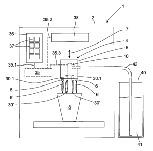
Figure 1 shows a front view of a coffee machine 1, which is
designed for the preparation of a plurality of different
beverages and to this end, in particular, for the
preparation of coffee, heated milk and foamed milk and for
the preparation of speciality coffees, which possibly
contain milk and/or milk foam. On the front face of a
housing 2 of the coffee machine 1 a coffee outlet head 4 is
attached for dispensing a coffee beverage. In the present
CA 02688810 2010-01-06
BE-22814-CA
12
example, the coffee outlet head 4 comprises two coffee
outlets 6 for dispensing a coffee beverage and a housing 5
connected to the coffee outlets 6. The coffee outlets 6 and
the housing 5 are arranged to be vertically adjustable and
to this end (by means of guide means not shown in Figures 1
- 3) are guided on the housing 2 of the coffee machine 1 in
the direction of a vertical line, as is indicated in Figure
1 by a double arrow 7. In this manner it is possible to
adapt in an appropriate manner the vertical position of the
coffee outlet head 4 relative to a receptacle 8, which is
provided for receiving a coffee beverage dispensed via the
coffee outlets 6 and to this end is positioned below the
coffee outlets 6. As shown in Figure 1, the respectively
dispensed coffee beverage leaves the respective coffee
outlet 6 in the form of a coffee jet 6'.
A dispensing device 10 according to the invention for milk
and/or milk foam is further arranged on the front face of
the housing 2 of the coffee machine 1. In the present
example, the dispensing device 10 is fastened to the coffee
outlet head 4 and at least partially enclosed by the housing
5 of the coffee outlet head 4, as is explained in more
detail hereinafter in combination with Figure 3. As the
dispensing device 10 is fastened to the coffee outlet head
4, the dispensing device 10 together with the coffee outlet
head 4 is vertically adjustable relative to the receptacle
8.
As Figure 1 shows, in the interior of the coffee machine 1 a
control device 35 is accommodated, which controls all of the
processes which may be carried out by the coffee machine, in
particular the preparation and dispensing of the
respectively desired coffee beverages and the dispensing of
CA 02688810 2010-01-06
BE-22814-CA
13
milk and/or milk foam. The components of the coffee machine
1 involved in the preparation and the dispensing of the
respective coffee beverages are not shown in Figures 1 - 3
(apart from the coffee outlet head 4).
During operation, the coffee machine 1 may be operated by a
user by means of a control panel 36 arranged on the housing
2, which comprises a plurality of manually actuatable
buttons 37 (in the present example eight) and is connected
to the control device 35 via a line 35.1 for transmitting
data and/or control signals. A specific process which may be
carried out by the coffee machine is associated with each
individual button 37. By actuating the respective button 37,
a user may select the respectively desired beverage, in
particular from a predetermined list of a plurality of
different beverages, which may be prepared by means of the
coffee machine 1, and initiate the preparation of this
beverage.
The control device 35 is, moreover, connected via a line
35.2 for transmitting data and/or control signals to a
display 38 so that, by transmitting corresponding data
and/or control signals, it is possible to initiate the
representation of information about the respective operating
state of the coffee machine by means of the display 38.
As Figure 1 also indicates, the control device 35 is
connected via a line 35.3 for transmitting data and/or
control signals to the dispensing device 10 for milk and/or
milk foam, in order to be able to control a dispensing of
milk and/or milk foam (as is explained in more detail in
combination with Figures 2 and 3).
CA 02688810 2010-01-06
BE-22814-CA
14
In the present example, a container 40, which contains a
milk reservoir 41, is arranged adjacent to the coffee
machine 1. In order to permit the production of a beverage
containing milk and/or milk foam, the dispensing device 10
is connected to the container 40 via a pipe 42 immersed in
the milk reservoir 41. If required, a portion of milk may be
suctioned from the milk reservoir 41 via the pipe 42 -
initiated by the control device 35 - and in this manner
provided for supplying milk to the dispensing device 10. As
Figure 1 indicates, the dispensing device 10 has two outlets
30.1 via which milk and/or milk foam may flow out of the
dispensing device 10 in the form of a milk jet and/or milk
foam jet 30', for example into the receptacle 8 (Figure 1).
Thus it is possible to fill two receptacles 8 at the same
time to the same filling level.
The pipe 42 and/or a portion of the pipe 42 immersed in the
milk reservoir 41, may also be replaced by a lance and/or a
conduit. The container 40 may be provided with a cooling
device (for cooling the container 40 and/or for cooling the
milk reservoir 41) and with thermal insulation (relative to
the surroundings of the container 40), in order to keep the
milk reservoir 41 cool.
As Figure 1 indicates, the pipe 42 extends on an outer face
of the housing directly towards the dispensing device 10.
The dispensing device is in the present example also
arranged such that the milk supplied to the dispensing
device 10 does not have to be conveyed into the interior of
the coffee machine 1. In this manner, it is precluded that
milk residues may occur in the interior of the coffee
machine 1. All parts which come into contact with the milk
CA 02688810 2010-01-06
BE-22814-CA
are, therefore, easily accessible and may be monitored with
little effort and if required removed, replaced or cleaned.
With reference to Figures 2 and 3, further details of the
5 dispensing device 10 are outlined hereinafter.
As is revealed from Figures 2 and 3, the dispensing device
10 comprises, amongst other things, a mixing device 1 for
mixing steam, milk and/or air. The mixing device 11
10 comprises a housing 12 in which the following are arranged
and/or formed:
- a chamber 19,
- a first line 15 for the supply of milk into the chamber
15 19,
- a second line 16 for the supply of steam into the chamber
19,
- a third line 17 for the supply of air into the chamber
19,
- an outlet device 28 for milk and/or milk foam which
comprises an emulsifying chamber 29 connected to the
chamber 19 for receiving a mixture of steam, milk and/or
air produced in the chamber 19 and a bore 30 for the
outlet of milk and/or milk foam from the emulsifying
chamber 29 (and/or the mixing device 11), the bore 30 in
the present example opening into the two outlets 30.1 for
the milk and/or the milk foam, and
- a valve 21 comprising an adjustable regulating shaft 22
for regulating the supply of milk and/or air into the
chamber 19.
CA 02688810 2010-01-06
BE-22814-CA
16
The first line 15 may be connected via an adapter 15' to the
pipe 42, in order to ensure a supply of milk from the
container 40.
The second line 16 is connected to a steam generator of the
coffee machine 1 (not shown in Figures 1 - 3) in order to be
able to introduce steam if required into the second line.
As Figure 2 indicates, the third line 17 is open at the end
remote from the chamber 19 and permits at this end the entry
of ambient air into the line 17. The third line is
nevertheless provided with a non-return valve 18 (for
example in the form of a membrane valve) in order to ensure
that, on the one hand, ambient air may penetrate through an
air hole formed in the non-return valve 18 (limiting the
supply of air) into the third line 17 and thus into the
chamber 19 of the mixing device 11 and, on the other hand,
however, it is prevented that the milk supplied to the
mixing device 11 may escape via the third line 17 and
possibly soil the aforementioned air hole and thus impair
the supply of air via the third line 17 in an uncontrolled
manner.
As Figure 2 indicates, the second line 16 opens in the
present example into the chamber 19 via a nozzle 16' which
is formed such that steam which flows from the line 16 via
the nozzle 16' into the chamber 19 produces a vacuum in the
chamber 19 (according to the Venturi effect). As the first
line 15 (for milk) and the third line 17 (for air) also open
into the outlet device 28 via the chamber 19, a steam jet
injected into the chamber 19 via the second line 16 causes a
suction effect in the first line 15 and in the third line 17
and ensures that (without the assistance of further pumps)
CA 02688810 2010-01-06
BE-22814-CA
17
milk is suctioned via the first line 15 and possibly air via
the third line 17 into the chamber 19 and may be mixed
and/or swirled there with the steam, in order to heat the
milk (if no air is supplied via the third line 17) or to
foam the milk by swirling with air, and to produce a mixture
of heated milk and milk foam (if air is supplied via the
third line 17).
The regulating shaft 22 of the valve 21 is, in the present
case, configured as a cylindrical body which is mounted on
the inner walls of the housing 11 such that the regulating
shaft 22 may be rotated about its longitudinal axis 22.1 and
thus may be adjusted by rotations about the longitudinal
axis 22.1
As may be derived from Figure 3, the first line 15 and the
third line 17 open directly on an outer peripheral surface
22.2 of the regulating shaft 22 into the interior of the
housing 12, in Figure 3, the reference numeral 15.1 denoting
the corresponding opening of the first line 15 and the
reference numeral 17.1 denoting the corresponding opening of
the third line 17. Accordingly, the regulating shaft 22 may
close the opening 15.1 and/or the opening 17.1 and thus
prevent a supply of milk via the first line 15 into the
chamber 19 and/or a supply of air via the third line 17 into
the chamber 19, unless channels formed in the regulating
shaft 22 form a continuous connection between the first line
15 and the chamber 19 and/or between the third line 17 and
the chamber 19.
In order to permit that a supply of milk into the chamber 19
may be regulated by adjusting the regulating shaft 22 (i.e.
by a rotation about the longitudinal axis 22.1 by a specific
CA 02688810 2010-01-06
BE-22814-CA
18
angle of rotation), in the regulating shaft a channel 22.3
is formed, which is open towards the outer peripheral
surface 22.2 of the regulating shaft 22 and forms at the
opening 15.1 a through-passage between the first line 15 and
the chamber 19, the cross section of this through-passage
being dependent on the respective (angular) position of the
regulating shaft 22. In the example according to Figure 3,
the channel 22.3 and the first line 15 overlap at the
opening 15.1 such that the cross section of the through-
passage between the first line 15.1 and the chamber 19 is at
a maximum and thus a supply of milk through the channel 22.3
is possible at maximum flow rate. With a rotation of the
regulating shaft 22 about the longitudinal axis 22.1 by a
specific angle of rotation, the cross section of the
through-passage between the first line 15 and the chamber 19
may be altered and, in particular, reduced by a
predetermined amount, the size thereof depending on the
shape and arrangement of the channel 22.3, on the shape and
arrangement of the first line 15 and the respective angle of
rotation. Accordingly, by adjusting the regulating shaft 22
between different predetermined positions, a flow of milk
through the first line 15 into the chamber 19 may be altered
and possibly switched on and switched off.
In a similar manner, in the regulating shaft 22 a further
channel is formed (not shown in Figures 1 - 3), which
produces a through-passage between the third line 17 and the
chamber 19, the cross section thereof being able to be
altered according to the angle of rotation of the regulating
shaft 22. Accordingly, a flow of air through the third line
17 into the chamber 19 may be altered and optionally
switched on and switched off by adjusting the regulating
shaft 22 between different predetermined positions.
CA 02688810 2010-01-06
BE-22814-CA
19
As Figure 3 shows, the dispensing device 10 is provided with
a drive motor 25 (for example a stepping motor) which may be
activated by means of the control device 35 via the line
35.3, and is used to rotate and, as a result, to adjust the
regulating shaft 22 of the valve 21 about the longitudinal
axis 22.1 by controlling the control device 35.
The drive motor 25 has a drive shaft 26 which is arranged
axially to the longitudinal axis 22.1 of the regulating
shaft 22. The drive shaft 26 is preferably releasably
coupled to the rotational axis 22.1, in order to be able to
separate the mixing device 11 in the simplest possible
manner from the coffee outlet head 4 and/or the coffee
machine 1. In the present example, the regulating shaft 22
at one end comprises an axial bore 23 into which the drive
shaft 26 may be positively inserted in the direction of the
longitudinal axis 22.1. In order to produce a coupling
between the drive shaft 26 and the regulating shaft 22, the
mixing device 11 is positioned on the drive shaft 26 such
that one end of the drive shaft 26 protrudes into the bore
23. In order to improve the stability of the coupling, the
regulating shaft 22 may optionally be fixed by fastening
means (not shown in Figures 1 - 3) to the drive shaft 22.
The valve 21 is configured such that by a rotation
(adjustment) of the regulating shaft 22 between a plurality
of predetermined positions, both the supply of milk through
the first line 15 and also the supply of air through the
third line 17 may be varied. In this manner, milk and air
may be mixed in different quantities, the mixing ratio
between the milk and air being able to be varied over a
large range (for example between 100% and 0%).
CA 02688810 2010-01-06
BE-22814-CA
The respective predetermined positions are stored in the
control device 35 and it is possible to move into said
positions in a reproducible manner using the drive motor 25,
5 by controlling the control device 35, in a manner which is
automatic, rapid and has the respective desired accuracy.
In a variant three different predetermined positions are
provided:
- in a first position of the regulating shaft 22 (resting
position) the supply of milk into the chamber 19 is
closed and the supply of air into the chamber 19 is open
(with a maximum through-passage between the third line
17 and the chamber 19).
- in a second position of the regulating shaft 22 (milk
foam position) the supply of milk and the supply of air
into the chamber 19 are open (with a maximum through-
passage between the first line 15 and the chamber 19 and
with a maximum through-passage between the third line 17
and the chamber 19.
- in a third position of the regulating shaft 22 (milk
position) the supply of milk is restricted (relative to
the maximum through-passage between the first line 15
and the chamber 19) and the supply of air into the
chamber 19 is closed.
In a further variant, further predetermined positions are
provided which may be viewed as intermediate positions
relative to the aforementioned positions of the regulating
shaft 22. Proceeding from the aforementioned third position
CA 02688810 2010-01-06
BE-22814-CA
21
(milk position), for example, intermediate positions may be
defined in which the supply of milk is restricted to
different degrees of intensity (relative to the maximum
through-passage between the first line 15 and the chamber
19). By an adjustment of the regulating shaft 22 between
said intermediate positions it is possible to bring milk
(without the addition of milk foam) to different
temperatures.
Proceeding from the aforementioned second position (milk
foam position), for example, intermediate positions may be
defined in which the supply of air is restricted to
different degrees of intensity (relative to the maximum
through-passage between the third line 17 and the chamber
19). By an adjustment of the regulating shaft 22 between
said intermediate positions it is possible to alter the
consistency of the respectively produced milk foam by
varying the relative proportion of air mixed with the milk.
It is also possible, proceeding from the aforementioned
second position and the aforementioned first position, to
define intermediate positions in which both the supply of
milk and the supply of air are restricted to different
degrees of intensity (relative to the maximum through-
passage between the first line 15 and the chamber 19 and/or
relative to the maximum through-passage between the third
line 17 and the chamber 19) . By an adjustment of the
regulating shaft 22 between said intermediate positions it
is possible to alter the temperature and the consistency of
the respectively produced foamed milk.
In the coffee machine 1, different predetermined positions
of the regulating shaft 22 are respectively associated with
CA 02688810 2010-01-06
BE-22814-CA
22
a plurality of different buttons 37. A user of the coffee
machine may, therefore, preselect the respective desired
position of the regulating shaft 22 by actuating one of the
buttons 37 and cause the dispensing device 10 to mix steam,
milk and possibly air according to the selected position of
the regulating shaft.
In the case of the coffee machine 1, it is possible by means
of the control device 35 to initiate the dispensing of a
coffee beverage, and to move the regulating shaft 22 into at
least one of the predetermined positions before, during or
after the dispensing of the coffee beverage. Furthermore,
the control device 35 is configured such that the regulating
shaft 22 is able to be successively moved into different
predetermined positions before, during or after the
dispensing of the coffee beverage. These measures make it
possible to produce automatically a wide variety of
speciality coffees which contain milk and/or milk foam.
As Figure 3 shows, the drive motor 25 is arranged in the
interior of the housing 2 of the coffee machine 1, whilst
the mixing device 11 is arranged on the outside of the
housing 2. In this manner, the dispensing device 10 requires
a particularly small amount of space. In order to allow a
coupling between the regulating shaft 22 and the drive shaft
26 of the drive motor 25, the housing 2 has an opening 2.1
through which the drive shaft 2 protrudes into the space
outside the coffee machine 1. The drive shaft 26 protrudes,
furthermore, into the housing 5 of the coffee outlet head 4
and is, therefore, able to be coupled within the housing 5
to the regulating shaft 22.
CA 02688810 2010-01-06
BE-22814-CA
23
In order to be able to remove the mixing device 11, the
housing 5 has to be opened, for example by removing
individual segments of the housing 5. The mixing device 11
is then freely accessible and may be separated from the
drive shaft 22 and the adapter 15' and as a whole removed
from the coffee machine 1.
Alternatively, the drive shaft 26 of the drive motor 25
and/or the regulating shaft 22 and/or a gear mechanism
connecting the drive shaft 26 and the regulating shaft 22 or
a coupling connecting the drive shaft 26 and the regulating
shaft 22 may be arranged such that they protrude through an
opening in the housing 2 of the coffee machine 1. According
to a further alternative, the drive 25 may also be
accommodated in the housing 5, provided the space in the
housing is sufficient.