Note: Descriptions are shown in the official language in which they were submitted.
Mk 02688962 2009-12-21
- 1 -
AUTOMATIC BAG HANDLING SYSTEM AND METHOD
FOR PRECISELY SECURING A PLASTIC HANDLE
TO A PLASTIC BAG
TECHNICAL FIELD
[0001] The
present invention relates to a computer
controlled automated bag handling system and method for
precisely securing a plastic handle to a plastic bag.
BACKGROUND ART
[0002] It
is known to secure all sorts of handles to
different sizes of bags either manually, semi-automatically
or fully automatically. However, these systems and methods
are not precise, are slow due to the fact that they are on-
line systems along which, repetitive functions are performed.
If one of the functions experiences a malfunction, then the
entire assembly line is stopped and this results in added
cost and all sorts of other problems. Also, these automated
or semi-automated systems require manual loading of bags and
slow handle attaching processes. The packaging of the bags
is also labour intensive.
[0003] With
some specialty plastic bags it is required to
secure a handle at a very precise location along an edge of
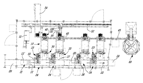
the bag. This
is particularly the case with heavy-duty
plastic bags provided with a perforated tear spout in a
corner area of the bag to dispense heavy material therefrom
such as salt pellets, or other granular products. Such a bag
is disclosed in our pending U.S. Patent Applicaton entitled
"Heavy-Duty Plastic Bag With Easy Tear Corner Spout Portion"
and bearing Ser. No. 12/222,934 filed on August 20, 2008.
SUMMARY OF INVENTION
[0004] It
is therefore a feature of the present invention
to provide an automatic bag handling system and method for
precisely attaching a plastic handle to a plastic bag and
which substantially overcomes all of the above-mentioned
disadvantages of the prior art.
Mk 02688962 2009-12-21
- 2 -
[0005] Another feature of the present invention is to
provide an automatic handle attaching system for securing a
plastic handle along an edge of a bag, which edge is also
provided with a perforated tear spout in a corner area of the
edge to which the handle is secured.
[0006] Another feature of the present invention is to
provide an automatic handle attaching system which is
computer controlled and capable of automatically supplying
bags, handling the bag to weld the handle thereto at a
precise location, to transfer the bag with the handle to a
group forming station to form a bag bundle and to secure the
bundle for shipping at a further station.
[0007] Another feature of the present invention is to
provide an automatic handle attaching system including an
automated bag handling mechanism which is computer-controlled
and capable of picking up a top bag from a group of offset
bags and which bag may be out of alignment and transfer same
while re-orienting the bag to a precise location in an
ultrasonic welding device.
[0008] Another feature of the present invention is to
provide a method of attaching a plastic handle at a precise
location on an edge of a preformed plastic bag which is
transferred from a conveyor while the conveyor is in movement
and transferring and re-orienting the bag to a handle
securing station for welding the handle thereto.
[0009] Another feature of the present invention is to
provide an automatic handle attaching system capable of
inspecting the bags during handling to reject and remove bags
of inferior quality during the process.
[00010] According to the above features, from a broad
aspect, the present invention provides an automatic handle
attaching system for precisely securing a plastic handle on
an edge of a preformed plastic bag. The system comprises a
delivery conveyor for conveying spaced-apart groups of flat
plastic bags. Each group of bags has two or more bags
disposed one on top of the other and offset along a leading
straight edge thereof which is oriented approximately
Mk 02688962 2009-12-21
- 3 -
transverse to a conveying direction of the delivery conveyor.
Two or more automated bag handling mechanisms are disposed
spaced-apart adjacent the delivery conveyor at respective bag
transfer stations. Each
bag handling mechanism is
independently operated and has an orientable bag engaging
hand secured to an articulated arm.
Detection means is
provided at each of the bag transfer stations to detect the
orientation and position of a top one of the bags of one of
the groups at the bag transfer stations. Control means is
provided to position the bag engaging hand to engage the top
one of the bags at its associated bag transfer station as the
groups of bags are conveyed by the conveyor. The articulated
arm displaces the bag engaging hand to precisely position the
leading straight edge of the bag at a precise location at a
handle securing station having bag position detection means
and handle attachment means.
Means is also provided to
transfer the bag with the handle secured thereto and to
position a further handle in the handle attachment means at
the handle securing station.
[00011]
According to a further broad aspect of the present
invention there is provided a method of attaching a plastic
handle at a precise location on an edge of a preformed
plastic bag. The method comprises the steps of conveying on
a delivery conveyor a plurality of spaced-apart groups of the
plastic bags. Each group contains a predetermined number of
bags in a flat form disposed one on top of the other and
offset along a leading straight edge thereof. The straight
edges of the bags are oriented approximately transverse to a
conveying direction of the delivery conveyor. The
method
further comprises detecting the orientation and position of a
top one of the bags as they are conveyed at at least two bag
transfer stations and wherein the bags may have been
subjected to slight displacement. The
method further
comprises engaging the top one of the bags by a bag engaging
hand oriented by a controller to coincide with the detected
orientation and position of the top one of the bags. The
method further comprises transferring the engaged top one of
Mk 02688962 2009-12-21
- 4 -
the bags to a handle securing station with the leading
straight edge thereof disposed at a precise location relative
to the plastic handle retained at the handle securing
station. The
handle is then secured onto the bag at the
precise location. The
bag with the welded handle is then
transferred away from the handle securing station for further
processing. The
method further comprises positioning a
further handle at the handle securing station to receive a
further top one of a following group of the groups of bags
conveyed at the bag transfer station. The groups of bags are
conveyed in an uninterrupted manner through the bag transfer
station.
BRIEF DESCRIPTION OF DRAWINGS
[00012] A
preferred embodiment of the present invention
will now be described with reference to the accompanying
drawings in which:
[00013] FIG.
1 is a top view of the automatic handle
attaching system of the present invention;
[00014] FIG. 2 is a side view of Figure 1;
[00015] FIG. 3 is a
perspective rear view of the
automatic handle attaching system of the present invention;
[00016] FIG. 4 is a
top view of the automated bag
handling mechanism, herein a computer-controlled robot and
illustrating its relationship with respect to a feed
conveyor, a handle securing station and a bag bundle
retrieving and transporting mechanism;
[00017] FIG. 5 is a
perspective view of a plastic handle
adapted for securement to a top edge of a plastic bag;
[00018] FIG. 6 is a
plan view, partly fragmented, of a
plastic bag having the handle secured thereto;
[00019] FIG.
7A is a top view of the handle securing
station;
[00020] FIG.
7B is a perspective view of the handle
securing station;
[00021] FIG. 8 is a
perspective view of the motorized
hand gripping transfer assembly;
Mk 02688962 2009-12-21
- 5 -
[00022] FIG.
9 is a perspective view of the bag
accumulating and transfer magazine;
[00023] FIG.
10 is a top view showing a handle disposed in
a dead nest where the handle is picked up by the gripping
fingers to be transported to the handle securing station;
[00024] FIG.
11 is a perspective view of the bag bundle
retrieving and transporting mechanism;
[00025] FIG.
12 is a perspective view illustrating the
construction of the orientable bag engaging handle of the
robot showing the adjustable suction cups; and
[00026] FIG.
13 is a top view of an infeed conveyor system
which orients bags fed in a continuous shingle arrangement
from a bag former and re-orients these bags in groups of four
and transfers them to the conveyor of the automatic handle
attaching system of the present invention.
DESCRIPTION OF PREFERRED EMBODIMENTS
[00027]
Referring now to the drawings and more specifically
to Figures 1 to 4, there is shown generally at 10 the
automatic handle attaching system of the present invention
for precisely securing a plastic handle 11, as shown in
Figure 5, to an edge 12 of a plastic bag 13, as shown in
Figure 6. The
plastic bag 13 is formed by a bag forming
machine and comprises a front wall 14 and a rear wall 15
interconnected at opposed side edges 16 and 16'. The
top
open end of the bag is sealed by a seal line 17 and the
bottom end 18 of the bag is open for later inserting a
product therein. A perforated spout profile 19 is formed by
perforations in a corner of the sealed end of the bag. The
automatic handle attaching system 10 of the present invention
secures the handle 11 substantially centrally on the top edge
12 of the plastic bag 13 and spaced a predetermined distance
from the perforated spout profile 19.
[00028]
Referring to Figures 1 to 4, the automatic handle
attaching system 10 comprises a delivery conveyor 20 for
conveying spaced-apart groups 21 of the plastic bags 13. As
shown in Figure 1, each group 21 has two or more bags
Mk 02688962 2009-12-21
- 6 -
disposed one on top of the other and offset along a leading
straight edge which is the edge 12 of the bag as shown in
Figure 6. More specifically, in the illustrated embodiment,
each group 21 is comprised of four flat plastic bags disposed
offset one on top of each other. As also hereinshown, the
bags are oriented whereby the leading straight edge 12 is
disposed approximately transverse to the conveying direction,
as indicated by arrow 22 of the delivery conveyor.
[00029] Two
or more automated bag handling mechanisms 23,
herein four of such mechanisms 23 constituted by robots, are
disposed spaced-apart adjacent the conveyor 20 at respective
bag transfer stations 24. As better shown in Figure 4, each
of the bag handling mechanisms, namely the robots 23, are
independently operated by a control means, herein a computer
controlled controller 25. Each
robot 23 has an orientable
bag engaging hand 26 secured to an articulated arm 27.
[00030]
Detection means in the form of cameras 28, as shown
in Figure 2, are disposed at a precise elevated position at
each of the transfer stations 24 whereby to detect the
precise orientation and position of a top bag of the groups
of bags 13, namely bag 13' as shown in Figure 1 and to feed
video signal data to the controller 25. The controller 25 is
a programmable controller having a computer provided with a
memory in which are stored executable instructions. The
computer analyzes the video signal data which indicates the
position and orientation of the top one of the bags, namely
bag 13', inside a predefined perimeter area, as stored in the
memory of the computer, and causes the articulated arm 27 of
the robot 23 and the bag engaging hand 26 to orient itself in
conformity with the orientation of the top bag 13'. The bag
engaging hand 27 is thus positioned to engage a top one of
the bags as the groups of bags 21 continue to be conveyed by
the delivery conveyor 20 at its associated bag transfer
station 24. It is pointed out that the delivery conveyor 20
is in constant movement and its speed is controlled by the
controller 25 in synchronism with the other devices of the
system. The bag engaging hand 26 is provided with suction
Mk 02688962 2009-12-21
- 7 -
cups to pick up the top bag 23', as will be described later,
and the articulated arm transfers the hand 26 and the top bag
13' to a handle securing station 30.
[00031] As
better shown in Figures 7A and 7B, the handle
securing station 30 is provided with bag detection means,
herein a further fine-tuning camera 31 secured at an elevated
position over the handle securing station 30. A
handle
attachment means in the form of an ultrasonic welding jaw or
horn, of an ultrasonic welder device 32, is also provided.
The handle 11 is provided with an attachment portion or
channel 34 formed by angulated lower flaps 33 angulated
outwards from one another whereby to define the attachment
channel 34 therebetween, as shown in Figure 5. The handle 11
is retained in a nest 32' precisely positioned at the end
edge 37' of the table 37 with respect to the ultrasonic
welding horn whereby to receive a top edge portion of the
plastic bag 13' in between the open flaps 33. The camera 31
fine tunes the positioning of the top leading edge 12 of the
bag and feeds video signal data to the controller whereby it
precisely aligns the bag with respect to the nest in which
the handle is positioned. Once the top edge of the bag is in
position within the flaps 33 of the handle, clamps 35 are
actuated to clamp the bag in position. The
ultrasonic
welding horn 32 is then closed and the handle is
ultrasonically welded to the top edge of the bag. A sensor,
not shown, verifies the position of the handle with respect
to the corner of the bag in which the perforated spout
profile is formed and if within tolerances, as programmed
with the memory of the controller, will send an acceptance
signal to the controller to accept the bag. If outside these
tolerances the bag will be rejected in a fashion as will be
described later.
[00032] As
also additionally shown in Figure 4, the handle
securing station has a bag support table 37, as above-
mentioned, on which the bag is laid down during its
positioning in the welding assembly. If a
bag is to be
rejected because the handle is improperly secured, the
Mk 02688962 2009-12-21
- 8 -
articulated arm moves the bag engaging hand 26 to an
angulated forward position in front of the table 37 where
there is provided a bin or chute 32", see Figure 7B, to
receive rejected bags for recycling. A
perforated tool 36
perforates the spout profile 19 if necessary, if the bag
spout is not pre-perforated.
[00033]
Referring again to Figure 5, it can be seen that
the handle 11 has a handle grip 38 defining a hand passage 39
thereunder. It
also has an integrally molded reinforced
central rib 38' bridging the handle grip and the attachment
channel 34. This central rib of the handle 11 is gripped by
a transfer mechanism whereby to transfer the bag with the
handle secured thereto from the handle securing station 30 to
a bag accumulating magazine 40, as better shown in Figures 4
and 8B. The bag transfer means or mechanism is constituted
by a motorized hand gripper assembly 41, as shown in Figure
8A. The
gripper assembly 41 and two pairs of articulated
hands, 41' and 41", each having a pair of gripping fingers 42
and 43 and 41' and 43', respectively. These gripping fingers
constitute a handle positioner while others of the gripping
fingers engage the handle 11 from the handle securing station
to pull the bag therefrom and re-orient the handle with the
bag secured thereto in a position to deposit the handle with
the bag depending therefrom in the bag accumulating magazine
40 constituted by opposed pairs of spaced-part upwardly
inclined support pins 44 and 44', as shown in Figure 8B. The
gripping fingers 43 grip the central rib 38' of the handle 11
to position the handle, with the bag depending therefrom,
onto one set of the support pins 44 or 44' with the pins
extending through the handle passages 39 formed on opposed
sides of the central rib 38'. While the bag is deposited in
the magazine another pair of gripping fingers retrieves a
handle from a nest 61 of the handle conveyor 45, as shown in
Figure 10.
[00034] Bags
are accumulated onto the support pins until a
predetermined number of bags has been deposited in the
magazine as detected by the controller whereby to form a bag
Mk 02688962 2009-12-21
- 9 -
bundle. The motorized hand gripper assembly 41 moves back
and forth on a displaceable support between a handle supply
conveyor 45, positioned elevated above the bag accumulating
magazine 40 and the handle securing station 30. The pairs of
gripping fingers 41' and 42" are secured to an articulated
connection, not shown, while the gripping fingers are
depositing a bag into the bag accumulating magazine 40, the
other pair picks up a handle 11 from the handle supply track
or conveyor 45, in a manner as will be described later. When
the motorized hand gripper assembly moves to the handle
securing station 30, the gripping fingers position the handle
at a precise location within a nest under the welder horn,
after the bag is removed therefrom by other gripping fingers,
with the attachment channel 34 of the handle facing the
support table 37 and ready to receive another leading edge of
a further bag thereinto.
[00035] As shown in Figure 9, the bag accumulating magazine
40 has two displaceable magazine sections A and B. One of
the magazine sections is positioned at a bag receiving and
accumulating position, namely as illustrated by the position
of section A and the other section B is positioned at a bag
bundle discharge position, as shown in Figure 4, whereat a
bag bundle retrieving and transporting mechanism, herein a
gantry 50, as shown in Figure 11, picks up accumulated bags
from the magazine at a discharge position, as illustrated by
section B, to transfer the bundle to a securing machine 51
located at the end of a support rail 52 on which the carriage
53 of the bag bundle retrieving mechanism 50 is displaced. A
bundle securing machine 51, herein constituted by a strapping
machine, well known in the art, positions a strap through the
hand passages 39 of the accumulated handles 11 of the bundle
whereby to secure the bundle for packaging and shipping on
the outfeed conveyor 54.
[00036] As shown in Figure 11, the gantry SO has an arm 95
to which projects a pair of fingers, namely a static finger
96 and a sliding finger 97 which separate to enter
respectively the hand passages 39 of handles 11 of the
Mk 02688962 2009-12-21
- 10 -
accumulated bag bundle and close to clamp the handles,
whereafter the fingers are displaced to lift and retract the
arm 95 and therefore the bundle from the pair of pins 44.
The arm 95 is secured to a cylinder operated support 98. The
monitoring plate 99 is secured to a carriage 53 displaceable
on support rack 52, see Figure 1.
[00037] It
is pointed out that the computer of the
controller can be programmed for retrieving bags of different
sizes settings as set in the memory of its computer. The
program of the computer accommodates a range of bag sizes
from 10 to 20 inches wide and 20 to 30 inches long. The
system is set up and calibrated based upon a master bag of
known dimensions. In order to set up subsequent bag size to
be handled by the system, the user simply enters the bag
dimensions into an interface module of the computer and the
computer calculates the differences in dimensions between the
master bag specifications stored in the memory and feeds
these offsets to the robot to adjust to the desired bag size
to be processed. Based on these parameters, the controller
automatically adapts the system to handle different sizes and
different kinds of bags, as selected by the user. The
computer is also provided with vision software and monitors
all of the cameras of the system. A monitoring keyboard for
troubleshooting, not shown, is provided at a convenient
location.
[00038] Referring to Figure 12 there is shown the
construction of the bag-engaging hand which is connected to
the articulated arm 27 by an articulated coupling 80, as
shown in Figure 4, controlled by the controller. The
bag-
engaging hand 26 has a planar support frame 81 to which is
displaceably secured a plurality of suction cups 82. The
suction cups 82 are mounted on adjustable supports 83 whereby
to displace and position the support cups within a
predetermined area of the support frame cross-arms 81. The
frame is constructed such as to support sufficient suction
cups to accommodate bags of different sizes.
Vacuum is
provided to only those suction cups 83 which are dedicated to
Mk 02688962 2009-12-21
- 11 -
engage bags of the size placed on the delivery conveyor 20.
The suction cups 83 are spaced whereby to engage a top one of
the bags only with two cups being placed close to the leading
edge of the bag whereby to maintain this leading edge as taut
as possible for positioning within the channel 34 of the
handle 11.
[00039] The
fine-tuning camera 31 as shown in Figure 7A
provides accurate positioning of the bag within the weld
tolerances as stored in the computer's memory. The robot 23
brings the bag underneath the fine positioning camera 31 and
by doing so triggers the camera and the controller receives
data on the bag position as it is in motion. The camera 31
looks for the edge 16' of the bag adjacent the perforated
profile, as previously mentioned, as well as the points at
which the edges of the handle contact the top of the bag.
The camera then sends X-Y signal data to the robot. Since
the top of the bag is not perfectly straight, the vision
system only focuses on where the edge of the handle contacts
the bag and aims to make the skew or gap less than 1 mm
tolerance at these two points. If
the offset values are
outside the safe limits for the robot to place the bag onto
the table, the robot rejects the bag into the chute 32" or a
bin in front of the table, as previously described. Both
cameras 28 and 31 need to be calibrated when installed
whereby they are positioned at an exact position. To do so,
each tracking camera uses three engraved lines 55 for
calibration. The
lines are engraved on the side of the
delivery conveyor 20 located directly under the camera. The
mark lines 55 are within the camera field of view, see Figure
1.
000401 The
camera 28 is a line tracking camera and it
takes pictures every 100 mm of conveyor travel. Once
the
camera finds the bag entering the bag transfer station 24, it
determines its location and passes the data to the robot.
The robot picks the bag based on the location of the trailing
edge of the bag since it knows its location from the data
supplied by the camera as well as the bag dimensions as
Mk 02688962 2009-12-21
- 12 -
stored in the computer's memory. The robot is controlled to
target the theoretical center point of the bag and picks up
the top bag off the moving conveyor. As the robot transfers
the bag to the bag support table 37, the computer checks
inputting signals to determine if the welder horn is up, if a
perforator is installed adjacent the welder horn if the spout
perforations are to be punched in the bags being processed.
It also checks if a new handle is placed in the nest of the
welding assembly to receive the bag and if the bag clamping
mechanism is up before the robot moves into final position to
place the bag onto the table.
Before the robot shuts the
vacuum to the suction cups of the bag engaging hand 26 to
release the engaged bag, it triggers the holding clamps 35
which are provided with rubber plungers to hold the bag in
position within the handle channel during the welding
process. These clamps 35 remain engaged until the ultrasonic
welder starts welding. As soon as the clamps are engaged the
robot releases the bag and begins to move back to get the
next bag from the next group of bags being conveyed into its
bag transfer station 24. This action triggers the welder and
the perforator if such is provided at the station.
[00041]
After the welding operation is completed and the
welder horn has retracted, the sensor 36 inspects the welded
bag and handle to verify that the position of the welded
handle is within acceptable tolerances. If the finished bag
does not pass inspection, the robot removes the bag and
discharges it for recycling, as above described. If multiple
bags have failed in a row at the same weld station, then the
weld station is automatically shut down by the controller but
the other stations and their robots remain operative. An
accumulating bin 56 is provided at the end of the conveyor to
accumulate excess bags on the delivery conveyor due to a
shortage of one robot.
[00042] The
bag accumulating magazine 40, shown in Figure
8B, is a carousel system adapted to receive finished bags
from the welding station and hold them until a bundle of a
predetermined bag quantity is collected. Each
of the bag
Mk 02688962 2009-12-21
- 13 -
transfer stations is provided with this carousel which is
displaceable on a rotary actuator 40' 180 from a bag
accumulating position to a bundle discharge position. The
two sections A and B allow the system to keep running as one
section of the carousel is always being loaded. The carousel
is controlled and monitored by the controller.
Before the
carousel is displaced from its bag receiving position to its
bundle discharge position, the controller verifies that the
bundle retrieval mechanism is not in the station zone and
then it rotates the carousel to position the bag bundle for
gripping by the retrieval mechanism. As soon as the carousel
is rotated, the controller sends a signal to the motorized
hand gripper assembly. The carousel will usually wait until
a full bag bundle is removed before it can rotate again. To
avoid all the lanes becoming full with bag bundles at once
and overloading the bag bundle retrieving mechanism 50, the
filling of the carousel may be staggered. This is done by
prematurely indexing some carousels with less than the
predetermined number of bags required for a complete bundle.
For example, the controller may choose to index a particular
carousel prematurely, say with twelve (12) bags instead of
25. This presents a fresh set of support pins 44 to the hand
gripper assembly. Once the motorized hand gripper assembly
has loaded twenty-five bags onto the support pins 44, the
carousel will index again. This
will position the twenty-
five bags at the discharge position and bring the twelve bags
back to the loading position to continue loading. This
provides for a balanced work load for the bag bundle gantry
retrieving mechanism 50 and this is all controlled by the
controller.
[00043] As
previously described, handles 11 are supplied by
a handle supply track conveyor 45. At
the inlet of the
handle supply track conveyor 45 there is provided, as shown
in Figure 1, a bowl feeder 60. The
bowl feeder 60 is a
rotary unit and is able to achieve a feed rate sufficient to
supply handles to the four robots as shown in the system of
Figure 1. The bowl feeder is a device known in the art and
Mk 02688962 2009-12-21
- 14 -
it is adapted to supply the track conveyor 45 to distribute
handles to the robot welding stations. The track conveyor 45
has four presentation points 90, only one shown in Figure 10,
along its length, one for each bag transfer station. These
presentation points 90 have a stop cylinder 91 to singulate
and separate individual handles 11. A
push cylinder 91
transfers the individual handles into a dead nest 61 for the
motorized hand gripper assembly and more specifically the
gripper fingers to pick up the nested handle. When a handle
is positioned in the dead nest 61 a signal is sent to the
controller to indicate that the handle is ready for pick-up.
After the handle is picked up, the handle supply track 45
cycles again and readies a new handle for pick-up.
[00044] As
previously described, there are rejects during
the operation of each of the bag transfer stations. In fact,
there are three rejection locations in the system from the
point where the bag is transferred from the delivery conveyor
20 to its positioning in the carousel. The
first reject
location is at the end of the delivery conveyor 20 where the
bin 56 is provided. The second reject station is between the
table 37 at the handle securing station 30 and the delivery
conveyor 20. A third reject location is provided between the
handle securing station and the carousel wherein the
motorized hand gripper assembly 41 has the capability to
reject finished bags if the bag does not pass post-welding
inspection.
[00045]
Referring now to Figure 13, there will be described
the supply front end of the system. As
shown, a feed
conveyor 70 on which there is conveyed a supply of plastic
bags 13 in a shingled arrangement to feed the bags to the
system. The
bags are placed one on top of the other and
offset at the leading edge, herein with an offset overlap of
three inches. These bags are printed and have a sealed top
edge and an open bottom end. A sensor 71 is located above
the belt conveyor 70 and detects the leading edge 12 of the
first bag and initiates the cycle start of a linear bag
separator 72. The linear bag separator 72 is provided with a
Mk 02688962 2009-12-21
- 15 -
gripper assembly 73 which has suction cups and which is
lowered to touch the bags to be picked up. To
feed the
system of the present invention the bags must be grouped in
groups of four bags and accordingly the suction cups will
pick up four of the leading bags, or more, if there are more
robots 23 in the system and transfer them on an intermediate
belt conveyor 74. The
linear bag separator then turns 90
degrees and the suction to the suction cups is removed
whereby the four bags still in an overlap condition are
released onto the intermediate belt conveyor to form a
shingled group of four bags. Another linear bag separator 75
operates in the same fashion to transfer the groups of four
bags onto the delivery conveyor 20 to feed the automatic
handle attaching system 10 of the present invention. It is
also pointed out that there can be an alternate path if
another bag forming machine is used to supply shingled bags
on conveyor 70' located directly in front of conveyor 20.
Another linear bag separator 72' transfers those bags onto
conveyor 20 in synchronism with the linear bag separator 75.
[00046]
Briefly summarizing the method of operation of the
automatic handle attaching system of the present invention,
it consists essentially of the steps of conveying on a
delivery conveyor a plurality of spaced-apart groups of
plastic bags. Each group contains a predetermined number of
bags in a flat form disposed one on top of the other and
offset along a leading straight edge thereof. The straight
edges of the bags are oriented approximately transverse to a
conveying direction of the delivery conveyor. A
camera
detects the orientation and position of a top one of the bags
as they are conveyed into the transfer stations. During the
displacement of the bag groups along the delivery conveyor,
the bags may be subjected to slight displacement. The method
further comprises engaging the top one of the bags by a bag
engaging hand of a robot which is automatically oriented to
be co-incident with the detected orientation and position of
the top one of the bags. The bag engaging hand is provided
with suction cups to engage the top bag only and then to
Mk 02688962 2009-12-21
- 16 -
transfer the top bag to a handle securing station 30 with the
leading straight edge thereof disposed at a precise location
relative to the plastic handle retained at the handle
securing station. The
bag is precisely positioned with
respect to the handle disposed in the nest of the ultrasonic
welder. The handle is welded and a sensor verifies that the
handle is at a proper position with respect to a corner of
the bag which is then transferred by the motorized hand
gripper assembly to discharge the bag in a carousel and at
the same time pick up another handle from the handle supply
track conveyor. The motorized hand gripper then returns to
the handle securing station to remove the bag with the welded
handle and position a new handle within the nest while the
robot has retrieved a bag from the conveyor 20 which is now
ready to be repositioned into the handle.
[00047] Once
the carousel is filled with a predetermined
quantity of bags the controller will transfer these bags to a
retrieval position where the bag bundle retrieving gantry
mechanism will transfer the assembled bundle for strapping
and delivery to an outfeed conveyor.
[00048] As
illustrated there are four bag handling and
transfer stations 24 but additional ones can be added to
increase the output of the system.
[00049] It
is within the ambit of the present invention to
cover any obvious modifications of the preferred embodiment
described herein provided such modifications fall within the
scope of the appended claims.