Note: Descriptions are shown in the official language in which they were submitted.
CA 02689112 2009-11-30
WO 2008/153311
PCT/KR2008/003252
-1-
PARTITIONING OF FREQUENCY RESOURCES FOR TRANSMISSION
OF CONTROL SIGNALS AND DATA SIGNALS IN SC-FDMA
COMMUNICATION SYSTEMS
BACKGROUND OF THE INVENTION
1. Field of the Invention
The present invention is directed, in general, to wireless communication
systems and, more specifically, to a Single-Carrier Frequency Division
Multiple
Access (SC-FDMA) communication system and is further considered in the
development of the 3' Generation Partnership Project (3GPP) Evolved Universal
Terrestrial Radio Access (E-UTRA) long term evolution (LTE).
2. Description of the Art
In particular, the present invention considers partitioning resources
allocated to the transmissions of control signals and data signals in a SC-
FDMA
communication system. The invention assumes the UpLink (UL) communication
corresponding to signal transmissions from mobile User Equipments (UEs) to a
serving base station (or Node B). A UE, also commonly referred to as terminal
or
mobile station, may be fixed or mobile and may be a wireless device, a
cellular
phone, a personal computer device, a wireless modem card, etc. A Node B is
generally a fixed station and may also be called a Base Transceiver System
(BTS), an access point, or some other terminology.
Several types of signals need to be supported for the proper functionality
of the communication system. In addition to data signals, which convey the
information content of the communication, control signals also need to be
transmitted from the UEs to their serving Node B in the UL and from the
serving
Node B to the UEs in the DownLink (DL) in order to enable the proper
transmission of data signals. The DL refers to the communication from the Node
B to UEs. These control signals are subsequently described in detail with the
focus being on the UL.
The UEs are assumed to transmit data signals (or data packets) through
the Physical Uplink Shared CHannel (PUSCH). The PUSCH can be shared
CA 02689112 2009-11-30
WO 2008/153311
PCT/KR2008/003252
-2-
during the same time period by multiple UEs with each UE using a different
part
of the operating BandWidth (BW), as illustrated in FIG. 1, in order to avoid
mutual interference (Frequency Domain Multiplexing (FDM)). LTE1 110
transmits over BW 120 while UE2 130, UE3 150, and LTE4 170, transmit over
BW 140, BW 160, and BW 180, respectively. An exception is the use of Spatial
Division Multiple Access (SDMA) methods, where multiple UEs may share the
same RBs over the same sub-frame for their PUSCH data packet transmissions.
The Node B is assumed to transmit data signals (or data packets) to UEs
through the Physical Downlink Shared CHannel (PDSCH). Similarly to the
PUSCH, the PDSCH can be shared during the same time period by multiple UEs
through FDM.
PUSCH and PDSCH transmissions can be scheduled by the Node B
through a LTL or a DL scheduling assignment, respectively, using the Physical
Downlink Control CHannel (PDCCH) or they can be preconfigured to occur
periodically (persistent scheduling of PUSCH or PDSCH transmissions). Using
the PDCCH, a data signal transmission in the PUSCH or the PDSCH may
generally occur at any sub-frame decided by the Node B scheduler. Accordingly,
the scheduling of such transmissions is referred to as dynamic.
To avoid excessive PDCCH overhead, some PUSCH and PDSCH
transmissions may be configured to occur periodically at predetermined parts
of
the operating bandwidth. Such scheduling is referred to as persistent. FIG. 2
illustrates the concept of persistent scheduling where an initial packet
transmission 210 occurs periodically every assignment interval 220. Persistent
scheduling is typically used for communication services having relatively
small
bandwidth requirements per transmission period but need to be provided for
many
UEs making dynamic scheduling through the PDCCH inefficient due to the
associated overhead introduced in the DL of the communication system. One
typical example of such services is Voice over Internet Protocol (VoIP).
In response to the PUSCH and PDSCH transmissions, positive or negative
acknowledgement signals, ACK or NAK respectively, are assumed to be
transmitted to or from the UEs, respectively. As the invention considers the
UL of
CA 02689112 2009-11-30
WO 2008/153311 ,
PCT/KR2008/003252
-3-
the communication system, the focus will be on the ACK/NAK signals
transmitted by LTEs in response to a PDSCH transmission. ACK/NAK signaling is
required for use of Hybrid-Automatic Repeat reQuest (HARQ), where a data
packet is retransmitted upon the reception of a NAK and a new data packet it
transmitted upon the reception of an ACK.
Because the PDSCH scheduling of a UE in the DL can be dynamic or
persistent, the transmission of ACK/NAK signals from the UE is correspondingly
dynamic or persistent. In the latter case, similarly to the PDSCH
transmission, the
ACK/NAK transmission from the UE is periodic.
In addition to periodic and dynamic transmission of ACK/NAK signals,
other control signals may be periodically transmitted by UEs. One example of
such a control signal is the Channel Quality Indication (CQI). The CQI is
assumed to be sent periodically to inform the serving Node B of the channel
conditions, which can be represented by the Signal-to-Noise and Interference
Ratio (SINR) the UE experiences in the DL. Additional periodic transmissions
of
control signals other than CQI or ACK/NAK may also exist.
Therefore, the UL of the communication system is assumed to support
dynamic and persistent PUSCH transmissions, ACK/NAK transmissions due to
dynamic and persistent PDSCH transmissions, CQI transmissions, and possibly
other control signaling. The transmissions of CQI, persistent PUSCH, and
ACK/NAK due to persistent PDSCH are assumed to be periodic until deactivated
by the serving Node B or until the corresponding configured transmission
period
expires. The ACK/NAK and CQI signals will be jointly referred to as the
Physical Uplink Control CHannel (PUCCH). Other control signals may also be
periodically transmitted in the PUCCH.
The PUSCH transmissions are assumed to occur over a Transmission
Time Interval (TTI) corresponding to a sub-frame. FIG. 3 illustrates a block
diagram of the sub-frame structure 310 assumed in the exemplary embodiment of
the disclosed invention. The sub-frame includes of two slots. Each slot 320
further includes seven symbols and each symbol 330 further includes a Cyclic
Prefix (CP) for mitigating interference due to channel propagation effects.
The
CA 02689112 2009-11-30
WO 2008/153311
PCT/KR2008/003252
-4-
signal transmission in the two slots may or may not be in the same part of the
operating bandwidth.
In an exemplary sub-frame structure of FIG. 3, the middle symbol in each
slot carries the transmission of Reference Signals (RS) 340, also known as
pilot
signals, which are used for several purposes including for providing channel
estimation to allow coherent demodulation of the received signal. The number
of
symbols with RS transmission in the UL sub-frame may be different among the
PUSCH, the PUCCH with ACK/NAK transmission, and the PUCCH with CQI
transmission. For example, the middle three symbols in each slot may be used
for
RS transmission in case of ACK/NAK PUCCH transmissions (the remaining
symbols are used for ACK/NAK transmission) while the second and sixth
symbols in each slot may be used for RS transmission in case of CQI PUCCH
transmissions (the remaining symbols are used for CQI transmission). This is
also
illustrated in FIG. 9, FIG. 10, and FIG. 11, which will be described later
herein.
The transmission bandwidth is assumed to comprise of frequency resource
units, which will be referred to as Resource Blocks (RBs). The exemplary
embodiment assumes that each RB includes 12 SC-FDMA sub-carriers and LTEs
are assumed to be allocated a multiple N of consecutive RBs 350 for PUSCH
transmission and 1 RB for PUCCH transmission. Nevertheless, the above values
are only illustrative and not restrictive to the invention.
Although not material to the disclosed invention, an exemplary block
diagram of the transmitter structure for the PUSCH is illustrated in Figure 4.
If a
UE has both data and control (ACK/NAK, CQI, etc.) bits to transmit in the same
PUSCH sub-frame, then, in order to transmit the ACK/NAK, certain data bits
(such as, for example, the parity bits in the case of turbo coding) may be
punctured and replaced by the ACK/NAK bits. Simultaneous PUSCH and
PUCCH transmission by a UE is thus avoided and the single-carrier property is
preserved. Coded CQI bits 405 (if they exist) and coded data bits 410 are
multiplexed 420. If ACK/NAK bits also need to be transmitted in the PUSCH,
data bits (or possibly CQI bits) are punctured to accommodate ACK/NAK bits
430. The Discrete Fourier Transform (DFT) of the combined data bits and
control
bits is then obtained 440, the sub-carriers 450 corresponding to the assigned
CA 02689112 2009-11-30
WO 2008/153311
PCT/KR2008/003252
-5-
transmission bandwidth are selected 455, the Inverse Fast Fourier Transform
(IFFT) is performed 460 and finally the Cyclic Prefix (CP) 470 and filtering
480
are applied to the transmitted signal 490.
Zero padding is assumed to be inserted by a reference UE in sub-carriers
used by another UE and in guard sub-carriers (not shown). Moreover, for
brevity,
additional transmitter circuitry such as digital-to-analog converter, analog
filters,
amplifiers, and transmitter antennas as they are known in the art, are not
illustrated in FIG. 4. Similarly, the encoding process for the data bits and
the CQI
bits as well as the modulation process for all transmitted bits are well known
in
the art and are omitted for brevity.
At the receiver, the inverse (complementary) transmitter functions are
performed. This is conceptually illustrated in FIG. 5 where the reverse
operations
of those in FIG. 4 apply. As it is known in the art (not shown for brevity),
an
antenna receives the Radio-Frequency (RF) analog signal and after further
processing units (such as filters, amplifiers, frequency down-converters, and
analog-to-digital converters) the digital received signal 510 passes through a
time
windowing unit 520 and the CP is removed 530. Subsequently, the receiver unit
applies an FFT 540, selects 545 the sub-carriers 550 used by the transmitter,
applies an Inverse DFT (IDFT) 560, extracts the ACK/NAK bits and places
respective erasures for the data bits 570, and de-multiplexes 580 the CQI bits
590
and data bits 595. As for the transmitter, well known in the art receiver
functionalities such as channel estimation, demodulation, and decoding are not
shown for brevity and they are not material to the invention.
Also without being material to the disclosed invention, a block diagram of
the PUCCH (ACK/NAK, CQI) transmission structure is illustrated in FIG. 6. The
transmission is assumed to be through the modulation of Constant Amplitude
Zero Autocorrelation (CAZAC)-based sequences 610. Similarly, the RS
transmission is assumed to be through non-modulated CAZAC-based sequences
610. The sub-carriers corresponding to the assigned transmission bandwidth are
selected 620 and the sequence elements are mapped on the selected PUCCH sub-
carriers 630. The Inverse Fast Fourier Transform (IFFT) is performed 640, the
output is then cyclically shifted in the time domain 650, and finally the
Cyclic
CA 02689112 2009-11-30
WO 2008/153311
PCT/KR2008/003252
-6-
Prefix (CP) 660 and filtering 670 are applied to the transmitted signal 680.
With
respect to the PUSCH transmitter structure in FIG. 4, the main difference is
the
absence of a DFT block (because, although not required, the CAZAC-based
sequence is assumed to be directly mapped in the frequency domain to avoid the
DFT operation) and the application of the cyclic shift 650. In addition, Walsh
covering may apply to the ACK/NAK, RS, and possibly the CQI signals across
the corresponding symbols in the sub-frame (FIG. 3).
The reverse functions are performed for the reception of the CAZAC-
based sequence as illustrated in FIG. 7. The received signal 710 passes
through a
time windowing unit 720 and the CP is removed 730. Subsequently, the cyclic
shift is restored 740, an FFT 750 is applied, the sub-carriers 760 used by the
transmitter are selected 765, correlation with the replica 770 of the CAZAC-
based
sequence is applied 780 and the output 790 is obtained. The output can be
passed
to a channel estimation unit, such as a time-frequency interpolator, in case
of an
RS, or can be used for detecting the transmitted information, in case the
CAZAC-
based sequence is modulated by ACK/NAK or CQI information bits.
An example of CAZAC-based sequences is given by the following
Equation (1):
ck (n) = exp[i2Irk (n + n
2 ............................................................. (1)
In Equation (1), L is the length of the CAZAC sequence, n is the index of
a particular element of the sequence n = {0, 1, 2 L -
1}, and fmally, k is the
index of the sequence itself. For a given length L, there are L ¨ 1 distinct
sequences, provided that L is prime. Therefore, the entire family of sequences
is
defmed as k ranges in {1, 2 L -
1}. However, the CAZAC sequences used for
PUCCH signaling need not be generated using the exact above expression as it
is
further discussed below.
For CAZAC sequences of prime length L, the number of sequences is L-1.
As the RBs are assumed to include an even number of sub-carriers, with 1 RB
includes 12 sub-carriers, the sequences used to transmit the ACK/NAK and RS
can be generated, in the frequency or time domain, by either truncating a
longer
CA 02689112 2009-11-30
WO 2008/153311
PCT/KR2008/003252
-7-
prime length (such as length 13) CAZAC sequence or by extending a shorter
prime length (such as length 11) CAZAC sequence by repeating its first
element(s) at the end (cyclic extension), although the resulting sequences do
not
fulfill the definition of a CAZAC sequence. Alternatively, CAZAC sequences can
be generated through a computer search for sequences satisfying the CAZAC
properties.
Different cyclic shifts of the same CAZAC sequence provide orthogonal
CAZAC sequences. Therefore, different cyclic shifts of the same CAZAC
sequence can be allocated to different UEs in the same RB for their RS,
ACK/NAK, or CQI transmission and achieve orthogonal UE multiplexing. This
principle is illustrated in FIG. 8.
In order for the multiple CAZAC sequences 810, 830, 850, 870 generated
correspondingly from multiple cyclic shifts 820, 840, 860, 880 of the same
root
CAZAC sequence to be orthogonal, the cyclic shift value 890 should exceed the
channel propagation delay spread D (including a time uncertainty error and
filter
spillover effects). If Ts is the duration of one symbol, the number of cyclic
shifts
is equal to the mathematical floor of the ratio Ts/D. The cyclic shift
granularity
equals an element of the CAZAC sequence. For a CAZAC sequence of length 12,
the number of possible cyclic shifts is 12 and for symbol duration of about 66
microseconds (14 symbols in a 1 millisecond sub-frame), the time separation of
consecutive cyclic shifts is about 5.5 microseconds.
The CQI transmission parameters, such as the transmission RB and the
transmission sub-frame, are configured for each UE through higher layer
signaling and remain valid over time periods much longer than a sub-frame.
Similarly, the ACK/NAK transmission parameters due to persistent PDSCH
scheduling and the persistent PUSCH transmission parameters (such as the RB
and sub-frame) also remain the same over comparable time periods.
A consequence of SC-FDMA signaling is that the transmission bandwidth
of a signal needs to be contiguous. In order to avoid bandwidth fragmentation
for
PUSCH transmissions, the PUCCH transmissions need to be placed towards the
two ends of the operating bandwidth. Otherwise, if there are RBs available on
CA 02689112 2009-11-30
WO 2008/153311 PCT/KR2008/003252
. ,
-8-
each side of the PUCCH transmission bandwidth, they cannot be used for PUSCH
transmission by the same UE while preserving the single carrier property of
the
transmission.
Moreover, as PUCCH transmission includes periodic CQI transmissions,
periodic ACK/NAK transmissions, and dynamic ACK/NAK transmissions, an
appropriate ordering for the corresponding RBs at the two ends of the
operating
bandwidth needs to be determined.
In addition to PUCCH transmission, persistent scheduling of PUSCH
transmissions also results in similar bandwidth occupancy characteristics as
the
PUCCH.
SUMMARY OF THE INVENTION
Accordingly, the present invention has been designed to solve the above-
mentioned problems occurring in the prior art, and the present invention
provides
an apparatus and method for allocating frequency resources for the
transmission
of control signals and data signals from user equipments to their serving Node
B.
Additionally, the present invention determines the partitioning of RBs
allocated to PUCCH transmissions among the RBs used for CQI transmissions,
periodic ACK/NAK transmissions due to persistent PDSCH scheduling, and
dynamic ACKJNAK transmissions due to dynamic PDSCH scheduling.
Additionally, the present invention maximizes the bandwidth utilization
for PUSCH transmissions while accommodating the PUCCH transmissions.
Additionally, the present invention incorporates persistent PUSCH
transmissions while avoiding bandwidth fragmentation.
Additionally, the present invention facilitates the achievement of the
reception reliability requirements, particularly for control signals.
Additionally, the present invention informs the UEs of the first RB that is
CA 02689112 2013-01-28
-9-
available for dynamic ACK/NAK transmissions.
In accordance with an embodiment the present invention, there is provided a
method for the allocation of frequency units (resource blocks (RBs)), used by
control
signals having a periodic transmission, by control signals having dynamic
transmission,
and by data signals.
In accordance with another embodiment of the present invention, there is
provided a method for the allocation of frequency units used by control
signals having a
periodic transmission, by control signals having dynamic transmission, by data
signals
having periodic transmission, and by data signals having dynamic transmission.
In accordance with another embodiment of the present invention there is
provided
an apparatus and method for a user equipment, having transmission of an
acknowledgement signal in response to a data signal transmitted to it by the
serving Node
B using a respective scheduling assignment, to determine the first frequency
unit
available for the transmission of the acknowledgement signal.
In accordance with another embodiment of the invention, there is provided an
apparatus and method for a serving Node B to inform user equipments having
transmission of acknowledgement signals, in response to respective data
signals
transmitted by the serving Node B using respective scheduling assignments, of
the first
frequency unit available for the transmission of the acknowledgement signals.
According to an aspect of the present invention, there is provided a method
for
allocating, at a base station, frequency resources for transmission of control
signals and
data signals in an uplink over an operating bandwidth in a communication
system, the
control signals including first type control signals and second type control
signals,
wherein a first set of user equipments use first frequency resources for
transmission of
the first type control signals, a second set of user equipments use second
frequency
resources for transmission of the second type control signals, a third set of
user
equipments use third frequency resources for transmission of data signals, the
method
comprising:
CA 02689112 2013-01-28
-9a-
placing the second frequency resources between the first frequency resources
and
the third frequency resources on each side of the operating bandwidth; and
placing the third frequency resources between the second frequency resources,
wherein the first type control signals are Channel Quality Indication (CQI)
signals
that have periodic transmission, and the second type control signals are
acknowledgement signals being transmitted in response to transmission of
downlink data
signals.
According to another aspect of the present invention, there is provided a base
station for allocating frequency resources for transmission of control signals
and data
signals in an uplink over an operating bandwidth in a communication system,
the control
signals including first type control signals and second type control signals,
wherein a first
set of user equipments use first frequency resources for transmission of the
first type
control signals, a second set of user equipments use second frequency
resources for
transmission of the second type control signals, a third set of user
equipments use third
frequency resources for transmission of data signals, the base station
comprising:
a receiver for receiving the control signals and the data signals; and
a controller for placing the second frequency resources between the first
frequency resources and the third frequency resources on each side of the
operating
bandwidth and placing the third frequency resources between the second
frequency
resources,
wherein the first type control signals are Channel Quality Indication (CQI)
signals
that have periodic transmission, and the second type control signals are
acknowledgement signals being transmitted in response to transmission of
downlink data
signals.
According to a further aspect of the present invention, there is provided a
method
for transmitting, at a user equipment, a control signal in a communication
system to
which a frequency resource allocation scheme is applied, the frequency
resource
allocation scheme for allocating frequency resources for transmission of
control signals
and data signals in an uplink over an operating bandwidth in a communication
system,
the control signals including first type control signals and second type
control signals,
CA 02689112 2013-01-28
-9b-
wherein a first set of user equipments use first frequency resources for
transmission of
the first type control signals, a second set of user equipments use second
frequency
resources for transmission of the second type control signals, a third set of
user
equipments use third frequency resources for transmission of data signals, the
method
comprising:
if the user equipment belongs to the first set of user equipments,
transmitting the
first type control signal by using a resource allocated to the user equipment
among the
first frequency resources on each side of the operating bandwidth; and
if the user equipment belongs to the second set of user equipments,
transmitting
the second type control signal by using a resource allocated to the user
equipment among
the second frequency resources placed between the first frequency resources
and the third
frequency resources on each side of the operating bandwidth,
wherein the third frequency resources are placed between the second frequency
resources, the first type control signals are Channel Quality Indication (CQI)
signals that
have periodic transmission, and the second type control signals are
acknowledgement
signals being transmitted in response to transmission of downlink data
signals.
According to a further aspect of the present invention, there is provided a
user
equipment for transmitting a control signal in a communication system to which
a
frequency resource allocation scheme is applied, the frequency resource
allocation
scheme for allocating frequency resources for transmission of control signals
and data
signals in an uplink over an operating bandwidth in a communication system,
the control
signals including first type control signals and second type control signals,
wherein a first
set of user equipments use first frequency resources for transmission of the
first type
control signals, a second set of user equipments use second frequency
resources for
transmission of the second type control signals, a third set of user
equipments use third
frequency resources for transmission of data signals, the user equipment
comprising:
a transmitter for transmitting the control signal through an allocated
frequency
resource; and
a controller for controlling an operation of transmitting the first type
control
signal by using a resource allocated to the user equipment among the first
frequency
resources on each side of the operating bandwidth, if the user equipment
belongs to the
first set of user equipments, and an operation of transmitting the second type
control
CA 02689112 2013-01-28
-9c-
signal by using a resource allocated to the user equipment among the second
frequency
resources placed between the first frequency resources and the third frequency
resources
on each side of the operating bandwidth, if the user equipment belongs to the
second set
of user equipments,
wherein the third frequency resources are placed between the second frequency
resources, the first type control signals are Channel Quality Indication (CQI)
signals that
have periodic transmission, and the second type control signals are
acknowledgement
signals being transmitted in response to transmission of downlink data
signals.
BRIEF DESCRIPTION OF THE DRAWINGS
The above and other aspects, features, and advantages of the present invention
will be more apparent from the following detailed description taken in
conjunction with
the accompanying drawings, in which:
FIG. 1 is a diagram illustrating a partitioning of an operating bandwidth for
an
orthogonal transmission of signals from multiple UEs through frequency
division
multiplexing;
FIG. 2
is a diagram illustrating the concept of persistent (periodic) data
CA 02689112 2009-11-30
WO 2008/153311
PCT/KR2008/003252
-10-
signal transmission from a HE;
FIG. 3 is a block diagram illustrating an exemplary sub-frame structure
for the SC-FDMA communication system;
FIG. 4 is a block diagram illustrative of a first exemplary SC-FDMA
transmitter for multiplexing data bits, CQI bits, and ACK/NAK bits in a
transmission sub-frame;
FIG. 5 is a block diagram illustrative of an exemplary SC-FDMA receiver
for de-multiplexing data bits, CQI bits, and ACK/NAK bits in a reception sub-
frame;
FIG. 6 is a block diagram illustrating an exemplary transmitter for a
CAZAC-based sequence in a frequency domain;
FIG. 7 is a block diagram illustrating an exemplary receiver for a
CAZAC-based sequence in a frequency domain;
FIG. 8 is a block diagram illustrating an exemplary construction of
orthogonal CAZAC-based sequences through the application of different cyclic
shifts on a root CAZAC-based sequence;
FIG. 9 is a diagram illustrating an exemplary partitioning of resource
blocks for CQI, ACK/NAK, and data signal transmissions;
FIG. 10 is a diagram illustrating a first exemplary partitioning of resource
blocks for CQI, persistent and dynamic ACK/NAK, and persistent and dynamic
data signal transmissions; and
FIG. 11 is a diagram illustrating a second exemplary partitioning of
resource blocks for CQI, persistent and dynamic ACK/NAK, and persistent and
dynamic data signal transmissions.
DETAILED DESCRIPTION OF THE EXEMPLARY EMBODIMENTS
The present invention now will be described more fully hereinafter with
reference to the accompanying drawings. This invention may, however, be
embodied in many different forms and should not be construed as limited to the
embodiments set forth herein. Rather, these embodiments are provided so that
this disclosure will be thorough and complete and will fully convey the scope
of
the invention to those skilled in the art.
Additionally, although the present invention assumes a Single-Carrier
CA 02689112 2009-11-30
WO 2008/153311
PCT/KR2008/003252
-11-
Frequency Division Multiple Access (SC-FDMA) communication system, it also
applies to all FDM systems in general and to OFDMA, OFDM, FDMA, DFT-
spread OFDM, DFT-spread OFDMA, Single-Carrier OFDMA (SC¨OFDMA),
and single-carrier OFDM in particular.
System and methods of the embodiments of the invention solve problems
related to the need for maximizing the utilization of the available bandwidth
for
the transmission of signals from user equipments to a serving Node B, for
facilitating the achievement of desired transmission reliability targets, and
for
informing the UEs with transmission of acknowledgement signals of the first
frequency unit (or resource block (RB)) available for the transmission of
these
signals.
As discussed in the foregoing background, several signals in the UL have
a periodic nature and the corresponding allocation of resource blocks (RBs),
or
frequency units, per sub-frame can be predetermined over relatively long time
periods compared to the sub-frame duration. These signals include the CQI, the
ACK/NAK associated with persistent PDSCH transmissions, and the persistent
PUSCH. As it will be subsequently explained in detail, for several reasons,
including avoiding bandwidth fragmentation while supporting single carrier
transmission, it is desirable to place these signals towards the two edges
(ends) of
the operating bandwidth.
In addition to dynamically scheduled PUSCH transmissions, other signals
that may require a variable number of RBs per sub-frame include the ACK/NAK
for dynamic PDSCH transmissions (dynamic ACK/NAK). The RBs for dynamic
ACK/NAK transmissions should therefore be placed next to the ones for dynamic
PUSCH transmissions, start after the last RB allocated to periodic PUCCH and
PUSCH transmissions, and be placed towards the interior of the operating
BandWidth (BW).
The partitioning of periodic PUCCH transmissions, such as the CQI
signaling, and dynamic PUCCH ACK/NAK transmissions is first considered in
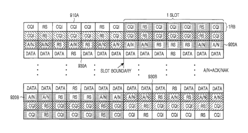
the exemplary setup illustrated in FIG. 9. The CQI transmission from a UE is
assumed to take place at the opposite ends of the operating BW in the first
slot
CA 02689112 2009-11-30
WO 2008/153311
PCT/KR2008/003252
-12-
910A and the second slot 910B. According to the invention, the RBs used for
dynamic ACK/NAK transmission from another, different, UE in the first slot
920A and the second slot 920B are placed to the interior of the ones used for
the
CQI transmission and are adjacent to and to the exterior of the RBs used for
dynamic PUSCH transmission in the first slot 930A and second slot 930B of the
sub-frame.
As the number of UEs having dynamic PDSCH transmissions in a sub-
frame may vary, the number of RBs used by the corresponding dynamic
ACK/NAK transmissions in the PUCCH may also vary per sub-frame (although
only one RB is illustrated in FIG. 9 for dynamic ACK/NAK transmissions). Such
variations cannot be expected in advance as the Node B scheduler is assumed to
operate without constraints on the number of assigned dynamic PDSCH
transmissions per sub-frame.
As each UE with dynamic ACK/NAK transmission is assumed to know
the multiplexing capacity in one RB (this parameter can be broadcasted by the
serving Node B) and its relative position with respect to ACK/NAK
transmissions
from other UEs (either through explicit signaling by the serving Node B or
implicitly, such as for example through the index of the PDCCH used for the
scheduling assignment), it can know which RB and which resource within the RB
(such as which cyclic shift of a CAZAC-based sequence) to use. For example, if
the ACK/NAK multiplexing capacity is 18 and the relative order of a UE for
ACK/NAK transmission is 20, that UE uses for its ACK/NAK transmission the
second resource in the second RB used for dynamic ACK/NAK transmissions. In
general, if the ACK/NAK multiplexing capacity in an RB is M and the relative
order of a UE with dynamic ACK/NAK transmission is P. the UE may use the
resource:
mod(P, M),
within the RB number of
Q = ceil(P/M),
where mod(, y) is x minus (n times y) where n equals to floor( x divided
by y). The "floor" operation rounds a number to its immediately smaller
integer
while the "ceil" operation rounds a number to its immediately larger integer.
CA 02689112 2009-11-30
WO 2008/153311
PCT/KR2008/003252
-13-
Placing the RBs for dynamic ACK/NAK transmissions towards the
interior of the operating bandwidth after the ones used for periodic PUCCH
transmissions (such as the CQI ones) for which the number of RBs per sub-frame
are fixed over long time periods, and adjacent and to the exterior of the RBs
used
for dynamic PUSCH transmissions, avoids bandwidth fragmentation or
bandwidth waste due to unused RBs. Otherwise, if the RBs for dynamic
ACK/NAK transmissions were placed before the ones for periodic PUCCH
transmissions and towards the exterior of the operating bandwidth, bandwidth
fragmentation would occur when the number of RBs for dynamic ACK/NAK
transmissions varied between sub-frames.
Instead, with the RB partitioning between periodic and dynamic PUCCH
transmissions as illustrated in FIG. 9, any variation in the number of RBs
used
for dynamic ACK/NAK transmissions can be seamlessly absorbed in the
scheduling of dynamic PUSCH transmissions in the remaining RBs without
resulting to any wasted RBs or causing bandwidth fragmentation as the former
RBs can simply be viewed as an extension of the latter and the reverse. The
serving Node B knows how many RBs will be required in every sub-frame for
dynamic ACK/NAK transmissions and can therefore accordingly allocate the RBs
for PUSCH transmissions without incurring bandwidth fragmentation.
Another reason for having the RBs for the dynamic ACK/NAK
transmissions in the interior of the ones allocated to periodic PUCCH
transmissions is that the former RBs can become available for PUSCH
transmission after a certain number of UL sub-frames. This happens when the DL
sub-frames carry multicast-broadcast traffic because there is no ACK/NAK
transmission in corresponding subsequent UL sub-frames (no unicast PDSCH
transmissions requiring ACK/NAK feedback are assumed to occur during
multicast-broadcast DL sub-frames). This may not be possible, due to the
single
carrier property, if the RBs for ACK/NAK transmission are not adjacent to the
ones for PUSCH transmission.
Yet another reason for having the dynamic ACK/NAK RBs in the interior
part of the operating bandwidth used for dynamic ACK/NAK and periodic
PUCCH transmissions is that the former typically need to be more reliable than
CA 02689112 2009-11-30
WO 2008/153311
PCT/KR2008/003252
-14-
the latter. Transmissions in interior RBs largely avoid out-of-band
interference
created by transmissions in adjacent bandwidths, which may be at a
substantially
larger power, and therefore ACK/NAK signals are better protected against such
interference if they are placed in interior RBs.
A generalization of the RB allocation of FIG. 9 is presented in FIG. 10
where in addition to the RBs for CQI, dynamic ACK/NAK, and dynamic PUSCH
transmissions, the RBs for persistent ACK/NAK and persistent PUSCH
transmissions are also included. The order of the periodic transmissions can
be
interchanged or mixed. Such an alternative order for the periodic
transmissions is
illustrated in FIG. 11.
The RBs for persistent ACK/NAK transmissions 1010A and 1010B or the
RBs for persistent PUSCH transmissions 1020A and 1020B are located to the
exterior of RBs for dynamic ACK/NAK transmissions 1030A and 1030B which
are again placed adjacent and to the exterior of the RBs for dynamic PUSCH
transmissions 1040A and 1040B because they are the only ones that may vary
between sub-frames in a way that cannot be predetermined. While the RBs for
the
periodic PUCCH and persistent PUSCH transmissions may also vary between
sub-frames, this happens in a predetermined manner.
Moreover, although in FIG. 10 the RBs for ACK/NAK transmission due
to persistent PDSCH scheduling are located in both slots to the interior of
the RBs
for CQI transmission, this is not necessary and the latter can be located to
the
interior of the former in one of the two slots. Additionally, the transmission
for
any of these signals may be confined in only one slot or extend past one sub-
frame.
FIG. 11 illustrates the same principle as FIG. 10 with the only difference
being the relative placement of persistent PUSCH 1110A and 1110B and CQI
transmissions 1120A and 1120B. As CQI transmissions typically require better
reception reliability than persistent PUSCH transmissions as the latter
benefit
from the use of HARQ, avoiding the CQI placement in RBs at the edge of the
operating bandwidth protects the CQI signal from potential out-of-band
interference and can therefore improve its reception reliability.
CA 02689112 2009-11-30
WO 2008/153311
PCT/KR2008/003252
-15-
In both FIG. 10 and FIG. 11, the RBs for persistent ACK/NAK
transmissions are located to the exterior of the RBs for dynamic ACK/NAK
transmissions and to the interior of the RBs for CQI transmissions or
persistent
PUSCH transmissions. In this manner, if there is no PDSCH scheduling in a
previous DL sub-frame, such as when that sub-frame conveys multicast-broadcast
communication traffic, no ACK/NAK transmission occurs in a corresponding
subsequent UL sub-frame and the RBs that would otherwise be used for
ACK/NAK transmissions by UEs can be used for PUSCH transmissions.
Having a fixed number of RBs per sub-frame for all periodic
transmissions (CQI, ACK/NAK due to persistent PDSCH scheduling, persistent
PUSCH scheduling), and placing the ACK/NAK RBs due to dynamic PDSCH
scheduling between the ones for periodic transmissions and the ones for
dynamic
PUSCH transmissions, the RBs available for dynamic PUSCH transmissions are
contiguous and well defined. This fixed number of RBs per sub-frame for the
periodic transmissions can be communicated to the UEs through a broadcast
channel. This information is used as an index by the UEs to determine the RBs
for dynamic ACK/NAK transmissions (first RB) if these RBs do not start from
the edges of the operating bandwidth. Knowing the fixed number of RBs per sub-
frame used for periodic transmissions, a UE can apply an offset equal to the
number of these RBs (equal to the index) in order to determine the first
available
RB for ACK/NAK transmission due to dynamic PDSCH scheduling.
Using FIG. 10 as an example, the serving Node B broadcasts the total
number of RBs used for all periodic transmissions (such as CQI, persistent
PUSCH scheduling, ACK/NAK due to persistent PDSCH scheduling) and this
value serves as an index for a lUE to determine the first RB available for
ACK/NAK transmission due to dynamic PDSCH scheduling by applying a
respective offset, equal to that index, relative to the first RB at either end
of the
operating bandwidth.
While the present invention has been shown and described with reference
to certain exemplary embodiments thereof, it will be understood by those
skilled
in the art that various changes in form and details may be made therein
without
departing from the spirit and scope of the present invention as defined by the
CA 02689112 2009-11-30
WO 2008/153311
PCT/KR2008/003252
-16-
appended claims.