Note: Descriptions are shown in the official language in which they were submitted.
CA 02689266 2009-12-23
1904
IMPROVED DISTRIBUTOR
FIELD OF THE INVENTION
This invention relates to distribution troughs. particularly a plurality and
network
thereof; to distribution towers comprising said distribution troughs and
particularly for use as
absorption and drying towers in the sulphuric acid contact process.
BACKGROUND OF THE INVENTION
Distributors are used to distribute a liquid throughout an area from a liquid
feed
source. Specifically, in an absorption tower a liquid is distributed across
the top of a packed
bed within the tower. A gas flows through the tower in generally counter-
current flow to the
liquid but it can also flow co-currently. The liquid is used to absorb a
chemical out of the gas
or a gas is used to strip a volatile component from a liquid. Examples in
sulphuric acid
production include absorption of sulphur trioxide gas, SO3, or of water vapour
into a strong
sulphuric acid solution: also the air stripping of sulphur dioxide, SO2, from
a sulphuric acid
stream. The efficacy of absorption or desorption is directly related to the
uniformity of the
liquid distribution.
A distributor may be considered as a single apparatus that may include several
distribution stages such as a single inlet source of liquid that is first
split into several but
generally a few flows (for example, less than, but not necessarily limited to,
10) for a header
or manifold system. Liquid is then distributed to a secondary system of
several conduits,
typically a greater number of conduits than in the first manifold, through one
or more feed
points in each secondary conduit. Each secondary conduit distributes liquid to
many
discharge points (e.g. >20), and may include a final stage of discharge means,
such as down
comer tubes, that direct the many discharge flows on to the packing.
Additional stages of
increasingly finer distribution can be contemplated, but preferable designs
will limit these
stages to as few as possible for cost-effectiveness.
There are many design variations for liquid distributors, but there are three
distributor
types generally recognized as pan or tray, closed conduit or pipe, and trough
types. The pan
or tray type of distributor has various means such as holes for a uniform
liquid distribution
1
CA 02689266 2009-12-23
but must also provide means such as gas risers for gas flow. The tray or pan
type is seldom
employed in towers larger than 1.5 meters diameter as they are relatively
expensive and
generally limited to smaller gas flows.
Pipe distributors are of relatively simple fabrication, generally using
readily available
piping components. A pipe distributor is typically an inlet pipe through the
vessel side wall
or vessel top head leading to a central manifold with several radial,
horizontal pipe branches;
or an inlet pipe into a single central horizontal pipe header through the wall
and several
perpendicular, horizontal side pipe branches; with a multitude of discharge
orifices along the
branch pipes. Pipe distributors can occupy a small overall cross-sectional
area when
designed for pressurized operation with high allowable pressure drop across
small discharge
orifices. However, disadvantages of pressurized pipe distributors include
difficulty obtaining
even liquid distribution when the inlet liquid also contains some gas or
solids; requiring
disassembly for cleaning; and producing fine liquid drops which are carried
over with
upward-flowing, high velocity gas.
Trough distributors use one or more, troughs to distribute the liquid
throughout the
tower. The troughs are generally arranged parallel to each other across the
tower. The liquid
distribution rate out of the troughs is controlled by the number of exit
liquid discharge points,
the size of the liquid discharge exits, and the surface height above the
exits. An initial feed
system comprised of a central feed pipe or feed trough is usually fed by means
of an inlet
pipe through the wall of the column, where the inlet pipe leads to the center
of the feed pipe
or feed trough or one end of the feed conduit. The initial feed system will
split the inlet feed
liquid into smaller flows to the distribution troughs and can be located above
and
perpendicularly across the lower troughs with liquid flow into each lower
trough through a
single inlet, or through two liquid flows from the opposite sides of the
central feed pipe or
trough, or through multiple liquid flows supplied by branches from the central
feed pipe or
feed trough. The trough type of distributor has an advantage over closed
conduit type
distributors of being open for easy inspection and solids clean out.
There are two main types of trough distributors based upon the kind of liquid
exits:
weir-type and orifice-type. Weir-type distributors have overflow weirs at or
near the top of
the trough, and are very sensitive to even small variations in liquid height
having a large
detrimental impact on uniform distribution. Orifice based distributors have
submerged exits
in the trough. Submerged orifices have flow rates less sensitive to the height
of the liquid
2
CA 02689266 2009-12-23
above them. However, orifices are more prone to becoming blocked with
suspended solids
that settle out when compared to weir-type distributors. Both orifices and
weirs can be
obstructed by large particles.
Distributors may also employ down comers, which are closed conduits, i.e.
tubes,
which further distribute liquid from discharge points of trough or conduit
type distributors
across the cross-section of the tower and down to the packing. These are
effective in
allowing for reduced number of distributor conduits while minimizing liquid
entrainment
within the gas stream.
In the sulphuric acid industry, pipe and trough distributors were
traditionally made
from ductile iron because of its ability to form a protective barrier to
strong sulphuric acid.
However, this barrier can be eroded off if the flow becomes turbulent. This
means that the
acid has to enter the distribution trough at a low velocity, which is
generally achieved by
having an overhead piping network to introduce the acid to the trough,
splitting the total flow
into smaller flows, at several points. Ductile iron troughs or pipes were also
designed with
large corrosion allowances making them very heavy.
Liquid introduced into packed towers will entrain solids, generally fine
particles, from
the slow wear of packing and other materials. Larger particles of solids found
in the liquid
are often small pieces of broken packing; usually occurring during the filling
of the tower
with the packing. Although means such as strainers or filters are employed to
remove solids,
such devices are not perfect and, in the sulphuric acid industry, the
materials of construction
suitable for filter elements have limited life. The solids in the liquid can
build up deposits in
distributors that cause mal-distribution and a periodic cleaning the equipment
is required with
subsequent loss of production. However, a higher liquid velocity will retard
the formation of
deposits by maintaining most solids in suspension to be swept out of the
distributor.
Many distributors in sulphuric acid towers are now manufactured out of
improved
acid resistant materials allowing higher velocities in acid contacted
equipment, piping, etc.
with reduced size, weight, and corrosion. Cost-effective acid resistant metal
alloys are
austenitic stainless steels having high silicon content such as SARAMET ,
registered to
Aker Solutions Canada, Inc. for use in sulphuric acid plants. However, as
liquid capacity is
increased through a trough distributor, i.e. reducing size with higher
velocities, difficulty
arises in maintaining a calm liquid surface at a uniform height above each
discharge exit; thus
different methods of introducing the liquid into the troughs at multiple
entrance points have
3
CA 02689266 2009-12-23
been employed in order to maintain low velocity and minimal disturbance of the
liquid
surface. In large towers of diameters greater than about 2 meters, several
feed conduits are
typically employed to provide several liquid entry points into the
distribution troughs.
However, the additional feed conduits reduce cost-effectiveness and are
inconvenient when
cleaning is required.
There is. however, a need for an improved distributor, assembly and towers
comprising such distributors.
LIST OF PUBLICATIONS
USP 3,146,609: 4,479,909; 5,014,740;
3,419,251; 4,557,877; 5,884,658;
4,267,978; 4,991,646; 5,919,405: and
4,272,026; 4,994.210; 6,758,463 B2.
SUMMARY OF THE INVENTION
An objective of the present invention is to provide a trough distributor with
a simple
and convenient feed conduit means while also providing for an even
distribution of liquid.
A further objective of the invention is to provide a trough distributor that
will reduce
cleaning frequency by preventing sedimentation that will block discharge
orifices.
Another objective of the invention is for its use in an improved and cost-
effective
tower for direct gas-liquid contact in for mass and/or heat transfer
processes.
Another further objective of the invention is its use in an improved sulphuric
acid
process.
The invention relates to a two-section, trough-type liquid distributor for use
generally
in direct gas-liquid contact devices for mass and/or heat transfer, and more
specifically in
columns with one or more sections of packing having random or structured
packing. The
invention is of particular utility in aspects of minimizing the number of feed
liquid entry
points for individual troughs of the distributor, most preferably reduced to
one entry point;
and of providing for liquid velocities to keep fine solids suspended in the
flow streams
throughout the distributor, thus avoiding build-up of finely divided
sediments. The invention
is of utility for both weir-type and submerged-orifice-type trough
distributors with the latter
4
CA 02689266 2009-12-23
type as a preferred embodiment. The invention may be used for reduced
distributor size in
many applications, or for high flow capacity, and has particular application
in absorption and
drying towers in sulphuric acid plants.
Accordingly, in one broad aspect, the invention provides a liquid distribution
trough
contained within a tower for the purpose of mass or thermal exchange between
at least a first
liquid and a second fluid;
said trough having an upper section and a lower section;
said lower section for receiving said first liquid;
a horizontal dividing member separating said upper section from said lower
section
and having at least one dividing member portion defining an aperture to allow
for passage of
said liquid fluid from said lower section to said upper section;
a feed conduit means in communication with said lower section to provide feed
first
liquid flow to said lower section;
said lower section having at least one inlet portion defining a liquid inlet
in
communication with said feed conduit means; and
a first baffle adjacent said inlet portion operably impacted by said first
liquid flow and
to hinder preferential flow along the walls of said trough and said dividing
member.
Preferably, the distributor has a set of at least one second baffle adjacent
at least one
of said dividing member apertures to direct a portion of said first liquid
flow through said
dividing member apertures into said upper section of said trough.
Yet more preferably, the distributor has a plurality of deflectors within said
upper
section, each of said deflectors located adjacent a dividing member aperture
and having a
portion defining a vertical surface and a portion defining a horizontal
surface to effect a
reverse essentially horizontal uniform distribution of flow of said first
liquid over the lower
surface of said upper section of said trough.
The feed conduit means, preferably, comprises a central feed conduit selected
from a
trough and a pipe.
Preferably, the upper section has portions defining discharge exits selected
from weir-
type or submerged orifice type by which the first liquid exits the upper
section of the trough;
and the discharge exits of the distribution troughs are submerged orifice type
located on the
upper trough section at a common elevation.
5
CA 02689266 2009-12-23
Preferably, the discharge exits communicate with downcomers which direct the
first
liquid flow.
Preferably, the first baffle is also so located ahead of the one aperture as
to operably
induce turbulence that provides more uniform velocity throughout the cross-
section of the
lower section of the trough and maintain suspension of most entrained solids.
Preferably, the set of at least one second baffle is also so located as to
induce
turbulence along the length of the trough that provides more uniform velocity
throughout the
cross-section of the lower section of the trough and maintain suspension of
most entrained
solids.
The deflector is, preferably, of a shape having vertical and horizontal
surfaces
selected from planar and curvilinear faces, wherein more preferably, the
vertical face is
perpendicular to the longitudinal axis of the distribution trough along which
the first fluid
flows and the horizontal face is perpendicular to the vertical axis of the
trough.
Preferably, the deflectors have angular or curvilinear shaped side-extensions
to the
faces perpendicular to the longitudinal axis of the distribution trough, which
extend at least
partly to the side walls of the upper section of the trough.
Preferably, the dividing member comprises a unitary plate having the
apertures, or
alternatively it comprises a plurality of plates providing the apertures
between adjacent
plates.
Preferably, each of the second set of baffles is aligned adjacent the
downstream back
edges of the apertures in the dividing member.
Preferably, the second set of baffles are an attached lower portion or
continued lower
portion of the deflector assemblies, wherein the lower portion extends through
the openings
into the lower trough section.
Preferably, the second set of baffles and the deflector assemblies are
integrally formed
portions of the plates.
Preferably, the distributor has screens to retain large particles in the lower
trough
section, adjacent the apertures.
The screens are, preferably, sized to retain particles larger than the size of
the
discharge exits of the troughs; preferably or alternatively sized to retain
particles larger than
about one fifth the size of the discharge exits of the troughs.
6
CA 02689266 2009-12-23
Preferably, the feed conduit means comprises an at least one downcomer for
each
liquid entrance to said trough.
In a further aspect, the invention provides, a network of distribution troughs
as
hereinabove defined.
In a yet further aspect, the invention provides, a tower for mass and/or heat
transfer
comprising one or more sections adapted to receive packing and incorporating a
distributor or
network thereof as hereinabove defined.
Preferably, the absorption tower and/or as the drying tower is of use in the
sulphuric
acid contact process.
In a yet further aspect, the invention provides, a sulphuric acid plant
comprising an
absorption tower and/or a drying tower having a distributor or a network of
distributors as
hereinabove defined.
In one preferred embodiment of the invention, an improved distributor is
provided
that does not require a network of feed conduits or a feed conduit with
branching feed
conduits. A single overhead conduit not having any branching feed conduits
feeding several
distribution troughs is sufficient. Where most prior art trough distributors
have multiple
liquid entrances, this embodiment of the invention requires only one entrance
for each
distribution trough. Each trough is divided into a longitudinal open upper
section and a
longitudinal, essentially enclosed, lower section having a single inlet flow
entering therein.
Instead of reducing flow velocities with multiple pipes, according to the
invention, dispersing
the liquid into the lower section, a single entry point is used with energy
dissipation and flow
deflecting baffle systems that are built into the lower section and into a
separating partition
plate or plates. There are spaced apertures in the partition plate or plates
separating the upper
and lower sections, for flow from the lower section into the upper section.
Baffles are
positioned in the vicinity of the aperture-openings, in the lower section,
which baffles redirect
a portion of the flow into the upper section. In the upper section a plurality
of vertical and
horizontal deflector assemblies are also positioned, comprised of vertical and
horizontal
surfaces, following the openings that re-direct the liquid flow for better
distribution. The
deflector assemblies cause a turbulent back flow of liquid along the top
surface of
partitioning plates which prevents solids from accumulating in spaces between
exit orifices.
The backflow is beneficial towards maintaining a uniform distribution of
liquid throughout
the upper section. Surprisingly, the additional and backward turbulence
induced by the
7
CA 02689266 2009-12-23
deflectors at the apertures is mostly restrained to the lower region of the
upper section and the
liquid surface above is made calmer than without the flow direction change.
This is achieved
by preventing the bulk fluid flow entering the upper section from directly
impacting the free
surface. and, instead, dissipating its energy to turbulence. The surface
calming and improved
distribution caused by the deflector, according to the invention, and energy
dissipation
systems resulting therefrom in the practise of the invention are beneficial to
both submerged
orifice type and weir type distributors. However, the benefits from sweeping
suspended
solids in the upper trough section are primarily beneficial to submerged
orifice type
distributors.
The invention is described in greater detail hereinbelow based upon a
submerged
orifice type, two-section trough distributor.
Some of the advantages of the invention may be summarized as follows:
= Requires only one entrance per trough distributor, which
o Eliminates the need for an overhead pipe distributor network of multiple
conduits:
o Reduces tower materials and fabrication labour/time costs; and
o Reduces installation and constructions time and costs.
= Design doesn't require tuning of adjusting inlets after installation to
balance flow
lengthwise along the trough;
= Field installation of additional feed conduits are not required;
= Reduces commissioning time and costs
= Further reduces construction cost
= Provides faster start-up for more production profit
= Distribution is insensitive to inlet velocity (limited to material limits);
= Uses a system of baffles to induce turbulence and redistribute flow
throughout the
lower section of the trough;
= Deflectors control the direction of flow to maintain a uniform distribution
along the
length of each trough;
= Greater flexibility in production rates matching demand;
= Less sedimentation issues compared to prior art due to increased liquid
velocity and
surface shear caused by deflectors in upper portion of the trough.
8
CA 02689266 2009-12-23
= Longer time for solids build-up reduces frequency of cleaning
= More on-line production profit
= Further reduces maintenance time/labour costs.
BRIEF DESCRIPTION OF THE DRAWINGS
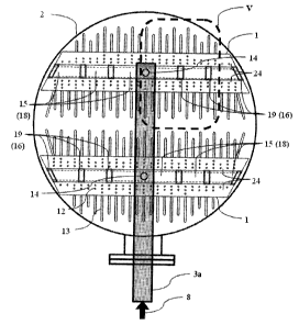
Fig. 1 is an isometric view of a sulphuric acid absorption tower shown
generally as
100, according to the prior art;
Fig. 2 is an isometric view of sulphuric acid absorption tower shown generally
as 200,
according to the invention;
Fig. 3 is a horizontal cross-sectional plan view of the absorption tower of
Fig.1, on the
plane AA-AA', according to the prior art;
Fig. 4 is a horizontal cross-sectional plan view of the absorption tower of
Fig. 2, on
the plane A-A', according to the invention;
Fig. 5 is an enlarged plan view portion below the feed conduit network 3a, in
part, of
Fig. 3, denoted as outlined location VV of Fig. 3, according to the prior art;
Fig. 6 is an enlarged plan view portion below the feed conduit 3, in part, of
Fig. 4,
denoted as outlined location V of Fig. 4; according to the invention;
Fig. 7 is a vertical partial cross-section view BB-BB', of Fig. 5, down the
longitudinal
center of the trough, according to the prior art;
Fig. 8 is a vertical partial cross-section view B-B', of Fig. 6, down the
longitudinal
center of the trough having geometry and flow patterns, according to the
invention;
Fig. 9 is a vertical cross-section view CC-CC', of Fig. 5, according to the
prior art;
Fig. 10 is a vertical cross-section view C-C', of Fig. 6, according to the
invention;
Fig. 11a is a fabrication plan view of a particular prepared plate 27b before
bending,
to combine several components of the invention in a single fabricated item;
Fig. I lb is a side view of the prepared plate 27b of Fig. 1la after bending,
combining
several components of the invention in a single fabricated item;
Figs. 12a and 12b show wire frame isometric illustrations of a portion of a
distribution
trough of the invention near the liquid inlet of the distribution trough,
including an exploded
view of the components (Fig. 12b);
9
CA 02689266 2009-12-23
Figs. 13a and 13b show wire frame isometric illustrations of a portion of a
distribution
trough of the invention at a distribution trough end, including an exploded
view of the
components (13b);
Fig. 14 shows examples of alternate baffle and deflector geometries according
to the
invention,
and wherein the same numerals denote like parts.
DETAILED DESCRIPTION OF PREFERRED EMBODIMENTS
The detailed description below exemplifies use of the invention in facilities
that
produce sulphuric acid, and in particular to use of the invention in
absorption towers of these
facilities.
Fig. I shows a packed tower 100 of recent prior art, having distribution
trough
network la and an overhead feed distribution network 3a. Sulphuric acid is
distributed into
distribution troughs la at multiple feed points 14a to reduce its velocity for
acceptable
erosion/corrosion rates, and also provide for a uniform distribution. Although
the recent use
of superior corrosion resistant high silicon austenitic stainless steel as the
material of
construction has reduced the size of distributor troughs la due to higher
allowed velocities,
flow capacity limitations occur in providing a uniform flow distribution and,
thus, multiple
feed points 14a are still required to reduce velocity for acceptable
uniformity of flow
distribution. A horizontal cross-section view of tower 100 shown as plane AA-
AA' in Fig. 1
is presented in Fig. 3 for greater detail of the prior art distribution
troughs la and the feed
distribution piping network 3a.
Tower 200 shown in Fig. 2 has two liquid distribution troughs 1 according to
the
invention. Troughs 1 distribute inlet liquid flow 8 uniformly across the top
of packing shown
as 6 supported by packing support 5. Liquid flows downward and exits tower 200
as the exit
liquid flow 9. In counter current tower 200, as shown, inlet S03-containing
gas flow 10
enters tower 200 into vestibule 4. The gas travels upwards through packing
support 5 and
packing 6 where heat and/or mass transfer occurs between the sulphuric acid
and the SO3
containing gas. S03-depleted gas then passes past the liquid distribution
system comprising
the simple inlet feed conduit network 3 and improved distribution troughs 1
having single
inlets 14 and flow deflectors 19 of use according to the invention. As the SO3
depleted gas
flows upward past the liquid distribution system liquid droplets may be
entrained and the gas
CA 02689266 2009-12-23
then passes through mist eliminators 7 to remove any liquid carry-over before
exiting tower
200 as gas outlet flow 11. Sulphuric acid inlet feed conduit 3 is shown with
feed flow 8, split
into flows entering through single inlets 14 of each distributor trough 1. A
cross-section plan
view of the tower, shown as plane A-A' in Fig. 2 is presented in Fig. 4 for
greater detail of
the improved distribution troughs 1 and the corresponding feed distribution
piping network 3.
Fig. 3, shows a tower plan view at cross-section plane AA-AA' of Fig. 1,
having two
distribution troughs la according to the prior art, each having multiple
inlets 14a and, on
trough side ledges 24, multiple submerged orifices 12, under which downcomer
tubes 13 are
attached for directing distribution trough exit flows over the entire cross-
sectional area and
down to packing 6. Feed liquid flow 8 is distributed through the feed
distribution piping
network 3a to multiple inlets 14a of prior art distribution troughs la. As
shown, feed
distribution piping network 3a comprises a central feed conduit and smaller
branching feed
conduits. The number of multiple inlets 14a is chosen for distributing smaller
inlet flows as
the number of inlets 14a is increased to thereby cause lower velocities
throughout the length
of distribution troughs 1 a. Lower velocities throughout the length of prior
art distribution
troughs la were necessary to ensure an even distribution of liquid. In older
prior art
distribution troughs constructed of ductile iron, lower velocities were also
necessary to avoid
accelerated wear. More detail for the outlined portion VV in Fig. 3, below
feed distribution
piping network 3a, is shown in the enlarged view of Fig. 5 and subsequent
cross-sectional
views of Figs. 7 and 9.
Fig. 4 shows two distribution troughs 1 according to the invention, each
having its
own single inlet 14- and, on trough side ledges 24, multiple submerged
orifices 12, under
which downcomer tubes 13 are attached for directing distribution trough exit
flows over the
entire cross-sectional area and down to the packing 6. Feed liquid flow 8 is
distributed
through feed distribution piping network 3 to single inlets 14 of improved
distribution
troughs 1, according to the invention. As shown, feed distribution piping
network 3
comprises only a central feed conduit. Single inlets 14, as compared to the
multiple inlets of
the prior art, inject higher velocity inlet flow into distribution troughs 1,
which includes flow
deflectors 19 that are one of the distinguishing features of the invention.
Improved
distribution trough 1 is shown to include a partitioning plate or plates 15,
lying attached to
and overlapping the inside edges of ledges 24, and which divide improved
distribution trough
1 into an upper open section 17 above ledges 24 and a lower trough section 18
under
11
CA 02689266 2009-12-23
partitioning plate or plates 15. As better shown in Figs. 8 and 12, inlet pipe
14 is connected
into lower section 18. The inlet flow into lower trough section 18 passes
through apertures
16 of partitioning plate/plates 15, which apertures are covered by flow
deflectors 19 in this
view into upper section 17. More detail for the outlined portion V, below feed
distribution
.5 piping network 3, is shown in the enlarged view of Fig. 6 and subsequent
cross-sectional
views of Figs. 8 and 10.
Fig. 5, enlargement of Fig. 3 plan-view outlined portion VV, shows two of
multiple
inlets 14a into prior art distribution trough la. Along a portion of trough
length,
longitudinally, the vertical cross-section view BB-BB' as located in Fig. 5,
is projected in
Fig. 7 for comparison with a similar cross-section side view in distribution
trough 1 of the
invention. Similarly, across the trough 1 (side-to-side), the vertical cross-
section view CC-
CC' as located in Fig. 7. is projected in Fig. 9.
Fig. 6, enlargement of Fig. 4 plan-view outlined portion V, indicates
horizontal
partition plate/plates 15 that create lower trough section 18, attached onto
horizontal side
ledges 24 of trough 1 where multiple submerged orifices 12 are located such
that all orifices
12 have a common liquid height above. Horizontal partition plates 15
incorporate deflectors
19, a significant feature of the invention, appearing as rectangles from above
and which cover
apertures 16 in plate/plates 15. Along a portion of trough length,
longitudinally, the vertical
cross-section view B-B' as located in Fig. 6, is projected in Fig. 8 to best
illustrate side views
of deflectors 19 and flow patterns due to deflector and baffle features of the
invention.
Across the trough (side-to-side), the vertical cross-section view C-C' as
located in Fig. 6, is
projected in Fig. 10 to best illustrate the horizontal ledges 24 and face view
of a typical
deflector assembly 19.
Fig. 7, longitudinal cross-section BB-BB' from Fig. 5, shows a portion of a
distribution trough la according to the recent prior art, wherein multiple
inlets 14a provide
divided sulphuric acid inlet flows 23a into the lower region. For clarity, a
majority of the
downcomers 13 has been removed and the included downcomers are truncated. The
included
downcomers 13 are shown, behind the trough wall with dashed lines, to extend
up to the side
horizontal ledge 24 where the downcomers are in fluid communication with
submerged
orifices (not shown) while submerged orifices 12 are shown in Fig. 9. In this
case of recent
prior art, the multiplicity of divided inlet flows 23a into trough la provide
for low velocities
12
CA 02689266 2009-12-23
suitable for ensuring even distribution of discharge flows along the length of
distribution
trough 1 a.
Fig. 8. longitudinal cross-section B-B' from Fig. 6, shows the two sections of
improved distribution trough 1 as upper section 17 and a lower section 18,
separated by a
horizontal partitioning plate or plates 15, which are attached on the inside
edges of horizontal
ledges 24. For clarity, the liquid height in upper section 17 is not shown.
Also a majority of
downcomers 13 has been removed while included downcomers 13 are truncated.
Upward
extension of the included downcomers to the horizontal side ledge 24 has been
not be shown.
Fig. 7 shows the extension as dashed lines. Inlet liquid feed distribution
conduit 3 (Fig. 2)
directs a liquid flow portion 23a, shown in Fig. 8, into each distribution
trough 1 by means of
a single pipe inlet 14 (Figs. 2, 4, 6 and 8). The inlet pipe diameter is
constrained by the width
of lower section 18 of trough 1. There are openings 16 in the horizontal plate
or between
each plate section 15, through which the fluid flows from lower section 18
into upper section
17. Flow arrows 23 (a through e) show the general direction of sulphuric acid
fluid flow.
Flow 23e through openings 16 is redirected by deflectors 19, first upwards and
then back
along the lower surface of upper section 17. opposite to its horizontal inlet
direction of travel
in the lower section.
In Fig. 8, when a straight pipe is used for single inlet 14, inlet flow 23a
impacts the far
wall, generally the bottom floor of the trough, flow arrow 23b, and
preferentially flows along
the floor. An "inlet" baffle or similar obstruction 22 on the floor opposing
the inlet flow and
positioned close to inlet 14, up to a short distance past first opening 16,
redirects the sulphuric
acid flow upwards and away from the opposing floor, flow arrow 23c. A minimum
of one
such baffle 22 on either side of flow inlet 23b is required on the impacted
floor. Inlet baffle
22 has been found to be important for inducing turbulence that helps to
provide a more
uniform velocity profile across the enclosed lower trough section 18. Other
profiles for
baffle 22 may also be used provided that they disrupt the preferential flow
along the wall
opposing the inlet pipe and, preferably, induce turbulence.
Beyond the inlet region, there are multiple apertures or openings 16 between
upper 17
and lower 18 sections of trough 1. There is a vertical baffle 20 in lower
section 18 in the
vicinity of each opening 16 to re-direct a portion of sulphuric acid flow up
through opening
16. Equally sized baffles 20 are conveniently fabricated and installed but,
some are scaled to
adjust the flow rate through each opening 16 in long distributors. Baffles 20
functions at any
13
CA 02689266 2009-12-23
elevation between the bottom and separating plate 15 in lower trough section
18. In a most
preferred embodiment, baffles 20 are located at the bottom of horizontal
partitioning plates
15 so that a deflector 19, partitioning plate 15, and vertical baffle 20 can
be fabricated from a
single piece of formable material. High silicon austenitic stainless steel is
the preferred
material in towers for sulphuric acid production and can be formed into plates
incorporating
several features, as shown in Fig. 11, using bending and cutting machines.
Each of baffles 20
also redirects sulphuric acid flow within lower trough section 18, as
illustrated by flow arrow
23d. Thus, these baffles 20 also induce turbulence that provides a more
uniform liquid flow
profile in lower trough section 18. In ductile iron distributors of prior art
for sulphuric acid
service, this turbulence would quickly corrode the exposed surfaces.
Referring again to Fig. 8, deflectors assemblies 19 are provided at the
downstream
edge of openings 16. In the absence of deflector assemblies 19, high inlet
flow velocities
cause flow through one opening 16 to continue in the horizontal direction and
add to
horizontal liquid flow from the next opening 16. This results in the surface
height of the
liquid to be higher at the far ends of trough 1 than at the center in a
stationary pattern and
high upward velocity causes significant local liquid level disturbances.
Deflectors 19 provide
obstruction across both the horizontal and upward directions of flow, and are
located at
openings 16 to maintain low average velocity in upper section 17 by directing
flows through
openings 16 into a horizontal, but reverse direction, 23e, along the bottom
surfaces of upper
trough section 17. A significant benefit is found in keeping the reverse
horizontal liquid flow
with an average velocity that is sufficient to maintain a shear force to sweep
away settling
solids.
Fig. 9. cross-section view CC-CC' of Fig. 5, is a side-to-side cross-section
through
inlet pipe 14a and distribution trough la of recent prior art showing the use
of many
submerged orifices 12, which are located at a common elevation on horizontal
wall sections
24 of trough la. This case of recent prior art shows no dividing partition for
two trough
sections although inlet pipes 14a are shown to extend into lower portion 18a
of the trough.
The prior art uses a multiplicity of inlet pipes 14a to provide many divided
inlet flows 23a
into trough for low velocities suitable for ensuring even distribution of
liquid discharge flows
along the length of distribution trough la.
Fig. 10, cross-section view C-C' of Fig. 6, is a side-to-side cross-section of
the
improved distribution trough 1 through a typical opening 16, (see Fig. 8)
showing that
14
CA 02689266 2009-12-23
deflector 19 spans the entire width of lower section 18 of trough 1 with side
overlap above
horizontal dividing wall plates 15. Liquid flow up-ward directing baffles 20
are shown
located at the top of lower section 18. The cross-section as shown in Fig. 10
shows the use
of many submerged orifices 12 located at a common elevation on horizontal side
ledges 24 of
trough 1. Flow arrows indicate typical flow paths into upper section 17 and
into submerged
orifices 12, as well as indicating back-eddy currents that maintain suspension
of fine
particles, and a sweeping action for re-entrainment of settled solids.
In a preferred embodiment, horizontal partitioning plate or plates 15 between
lower
18 and upper sections 17 is also used to support screens or similar filtering
devices in
openings 16 to restrain large solids particles entrained in the inlet flow in
lower section 18.
The size of screen openings are chosen to pass solids that are small enough to
avoid blockage
of orifices 12, i.e. less than the orifice size and, preferably, less than one
fifth of the orifice
size.
Figs. I la and l lb illustrate a deflector assembly 19 and baffle 20 formed as
parts of a
particular plate section 27b of dividing partition plates 15, from a single
piece of plate
material or sheet metal. Other differently dimensioned and bent plate sections
27a, 27c, and
27d at the inlet of and at the end of a distribution trough 1 are illustrated
in Figs. 12a. 12b,
13a and 13b.
In Fig. 1 la, particular plate 27b is cut to a suitable width and a length
that includes
lengths for horizontal and vertical portions 19a and 19b of deflector 19, a
length portion for
opening 16, and a length portion for lower section baffle 20. The so-prepared
plate is bent
along lines 28a, 28b, and 28c to form the profile illustrated in Fig. 1 lb.
Figs. 11a and 1 lb
illustrate a section of the horizontal plates with perforations 25 that are
used for openings 16,
and for support of finer screen 26, if necessary. For multiple partition
plates 27b between
the upper and lower sections, a consistent length of partition plate between
opening 16 and
deflector 19 is preferred but is varied as necessary, e.g. the distance
between the openings
may be altered at the trough ends and center. Before bending, particular plate
27b is further
prepared with punched, drilled, or cut holes 29 for bolting assembly, having
opening
perforations 25, and removal of corners 30 for fitting baffle 20 into lower
trough section 1.
For clarity, Figs. 12a, 12b, 13a and 13b do not include down comers that are
attached
under orifices 12.
CA 02689266 2009-12-23
Fig. 12, isometric wire frame assembly and exploded views of an inlet portion
of
trough 1, shows partition plates 27b, as described above and another
particular partitioning
plate 27a that is used at central trough inlet 14 supplying inlet liquid flow
23a. Inlet partition
plate 27a as shown is truncated but extends similarly in the opposite
direction from inlet 14,
i.e. symmetrically about centre-line 31. Partition plate 27a includes
perforated end sections
for the first of apertures 16 on either side of inlet 14. Partition plate 27a
also incorporates
inlet bottom baffle 22 as the lower part of an extended and bent portion 33 of
partition plate
27a, having opening 32 passing liquid through lower section 18 of trough 1.
Extended
portion 33 with bottom baffle 22 may also be prepared as a separate piece and
attached, e.g.
welded to partition plate 27a.
Figs 13a and 13b, isometric wire frame assembly and exploded views of an end
portion of trough 1. show two particular partition plates 27c and 27d forming
the last sections
of partitioning plates 15 before an end wall 36 of the trough. At the end
regions of each
trough I a perforated plate and/or screen 34 extending from separating plate
to the bottom of
the lower section 18 of trough 1 is included as a final means to filter and
collect
sedimentation. A diagonal perforated plate 34 or screen is preferably attached
to one of the
final separating plates 27c or 27d in trough 1 as shown on the second last
plate 27c in Figs.
13a and 13b, so that plate 27c and diagonal screen 34 can be removed in unison
for cleaning
of any accumulated sedimentation. The preferred geometry is a general diagonal
direction
extending downwards from the rear of the penultimate aperture 16 to trough 1
bottom and
extends towards the end of trough 1 such that solids are directed into a
pocket where they can
accumulate without preventing flow through the end openings. These are
particularly useful
during initial operation after new packing is introduced with some likely
breakage creating
larger sized solids.
Figs. 12a, 12b, 13a and 13b also indicate the use of bolts 35 to hold some
removable
plates in place which is necessary to facilitate solids clean-out. Other
plates are permanently
fixed in place by welding.
The side shape of deflectors 19 is not limited to the preferred angular form
as shown
in Fig. 8 and Fig. 14a but may also be, by way of example, of different
curvilinear shapes as
shown in Figs. 14b, c, d and e. In Fig. 14b, the leading edge 21 of deflector
19 is shown to
overlap an aperture 16 and a portion of partitioning plate 15. Fig. 14a and
14b show baffle 20
in lower trough section 18 to be aligned with deflector 19, while Fig. 14c, d
and e also show
16
CA 02689266 2009-12-23
different positions of vertical baffle 20 in lower trough section 18. Various
geometries may
be contemplated for the baffles and deflectors of use in the practise of the
invention in
accordance with the foregoing principles to allow for convenient fabrication
and installation.
EXAMPLE
The successful functioning of the present invention was discovered from
experimental
testing conducted using a small scale distributor trough. ,The small scale
model was made of
clear material to allow observation of liquid flow within trough 1 and to
determine the overall
performance of the distributor improvements compared to an equivalently sized
model
according to the prior art. The effects of individual features used in
improved distributor 1
were also observed by inserting and removing various components. Test work was
used to
adjust computer simulation models for accurate reproduction and computer
simulation gave
further insight into the flow patterns and effects of experimentally added
features.
Each added feature used in the improved distributor 2 was insufficient on its
own per
se to improve the overall performance of distributor 1. Thus, starting from an
empty trough
shell, each feature addressed a performance difficulty but often created a new
one. The
complete assembly of the improved distributor, according to the invention, was
able to
address all difficulties encountered.
The following description provides the effects of each feature as visually
observed
and further depicted in computer simulations.
The number and diameter of inlet pipes into the distribution trough determined
the
inlet velocity for any given flow rate.
In an empty trough 1, without any additional features, the use of multiple
inlets
achieved a sulphuric acid calm liquid surface with a near uniform
distribution. Problems
with the introduction of the liquid to trough 1 at a low velocity included
settling of suspended
solids and calmness of the liquid surface. These were significantly affected
by changes in
inlet velocity. Furthermore, the cost of adding more inlets to each trough 1
is expensive and
additional conduits made periodic cleaning more complicated and time-
consuming, and, thus,
thereby contribute to lost production and profit. However, just reducing the
number of inlets,
which increased inlet velocity, caused a detrimental effect on liquid surface
calmness, height
and liquid distribution.
17
CA 02689266 2009-12-23
In physical testing, and subsequent computer simulation, the number of inlets
to the
distribution trough model was reduced from ten to one. As the number of inlets
was reduced
to one, a flow pattern developed which formed a standing wave near the inlet.
This lead to a
very non-uniform liquid surface height and distinct liquid level difference
before and after the
standing wave.
A prior art feature comprising a partitioning plate having regularly spaced
apertures to
create an enclosed bottom section in fluid communication with an open upper
section was
installed and tested. At high liquid flow throughput, with the inlet liquid
flow introduced into
the bottom section, the standing wave flow pattern near the central feed inlet
did not
reappear. There was no distinct jump in liquid surface height as was observed
in trials with
no partition. However, flow rates through the partition apertures at the ends
of the trough
were substantially higher than the flow rates through the apertures closer to
the central inlet.
A stationary pattern of variable liquid height in the upper trough section was
observed with
the highest liquid levels at the outer ends of the trough, decreasing to the
lowest level in the
center. Subsequent computer simulations to model fluid flow in the trough
with, and without,
a partition were adjusted to reproduce the visually observed liquid surface
patterns. With a
partitioned trough, results of the adjusted model indicated the presence of a
strong
preferential current at the bottom of the lower trough section.
The variable liquid surface height in the trough prevents the equal discharge
flow
rates through submerged orifices having equally sized opening diameter and
other means to
achieve equal discharge flows are impractical. Such means include adjusting
orifice
diameters for the different liquid surface heights but this would greatly
limit the range of
operating capacity.
Baffles were introduced into the bottom section of the partitioned trough to
balance
flows through the apertures in the partitioning plate. Baffles were located
both in the vicinity
of each aperture and in the entrance region of the trough on the floor
opposing the inlet flow.
The baffles could be adjusted in position and size to achieve a reasonable
balance of flows
through the apertures.
The two locations of baffles addressed different issues. Baffles on the trough
floor
near the inlet disrupted the initial preferential flow along the bottom by
inducing turbulence
and redistributing the flow currents throughout the lower section of the
trough. In the
absence of the inlet bottom baffles the performance of the trough remained
very similar to a
18
CA 02689266 2009-12-23
trough with no baffles, i.e. high outer end liquid heights. A singular bottom
baffle on each
side of the entrance region was insufficient to properly distribute the flow
through each
aperture along the length of the trough, and an additional baffle in the
vicinity of each
aperture was found to be necessary. These additional baffles re-direct a
portion of the flow
from the lower section of the trough into the upper section, but in order for
the additional
baffles to function properly, it was necessary to first have even flow current
across the lower
trough cross-section, which was caused by the inlet baffles. However, as
subsequently seen
in computer simulation, the additional baffles also contributed to inducing
turbulence and
redistributing and maintaining even flow currents in the lower section along
the trough
length. Although the computer simulation showed an even liquid flow through
the apertures,
there was still a visually observed pattern of large liquid height differences
between the outer
ends and the center of the partitioned trough.
Flow entering the upper section was still primarily horizontal towards the
ends of the
trough. Introducing vertical deflectors at the downstream side of each
aperture on top of the
partitioning plate, was found to direct flow primarily upwards, further
improving liquid
distribution along the length of the trough. However, the vertical flows also
caused standing
waves to form above each opening. This allowed for the possibility of
splashing and also for
localized uneven discharge flows due to the surface waves.
Horizontal deflectors were placed over each aperture in conjunction with the
vertical
deflectors and the combined deflector assemblies were able to prevent standing
waves above
the apertures. In further testing, the addition of the deflector assemblies
was found to
minimize the previously found requirements for adjusting positions and sizes
of baffles in the
lower trough section. Mostly equal spacing and baffle sizes were now
sufficient for
achieving a remarkably calm and even height of liquid surface along the length
of the trough
at much higher flow capacity then used in previous trough designs. Further
computer
simulation, using adjusted model parameters for reproducing the visual
results, indicated that
the deflector assemblies in the upper section also redirected liquid to sweep
over the bottom
of the upper trough. The liquid velocity was generally maintained above solid
settling
velocity and the average shear stress across the bottom was able to either
sweep settled
particles out through the discharge orifices or cause re-entrainment.
In conclusion, it was seen that the combined effect of the baffles and
deflector
assemblies clearly provided an improved distribution trough with a reduced
number of inlets,
19
CA 02689266 2009-12-23
a uniform distribution along the length of the trough, a calm liquid surface,
and reduced
settling of solids when compared to the prior art.
Although this disclosure has described and illustrated certain preferred
embodiments
of the invention, it is to be understood that the invention is not restricted
to those particular
embodiments. Rather, the invention includes all embodiments which are
functional or
mechanical equivalence of the specific embodiments and features that have been
described
and illustrated.