Note: Descriptions are shown in the official language in which they were submitted.
CA 02690105 2010-01-14
1 APPARATUS AND METHOD FOR DOWNHOLE STEAM GENERATION AND
2 ENHANCED OIL RECOVERY
3
4
FIELD OF THE INVENTION
6 The present invention relates to an apparatus and a method for
7 creating a drive front for enhanced oil recovery. More specifically, a
downhole
8 burner first forms a combustion cavity in a hydrocarbon formation and then a
9 combination of steady state combustion and water injection above the cavity
creates
a steam and gas drive front in the hydrocarbon formation.
11
12 BACKGROUND OF THE INVENTION
13 It is known to conduct enhanced oil recovery (EOR) of hydrocarbons
14 from subterranean hydrocarbon formations after primary recovery processes
are no
longer feasible. FOR include thermal methods such as in-situ combustion, steam
16 flood, and miscible flooding which use various arrangements of stimulation
or
17 injection wells and production wells. In some techniques the stimulation
and
18 production wells may serve both duties. Other techniques include steam
flooding,
19 cyclic steam stimulation (CSS), in-situ combustion and steam assisted
gravity
drainage (SAGD). SAGD uses closely coupled, a horizontally-extending steam
21 injection well forming a steam chamber for mobilizing heavy oil for
recovery at a
22 substantially parallel and horizontally-extending production well.
23 Thermal methods of FOR can only be implemented in wells that have
24 been completed for thermal completions. Due to the high temperatures used
in
1
CA 02690105 2010-01-14
1 thermal completions, wells employing such FOR techniques must be completed
2 using materials, such as steel and cement, that can withstand high
temperatures.
3 Wells that were not completed with such high temperature resistant materials
cannot
4 implement thermal completions for EOR. Accordingly, well operators must
decide
on whether or not to implement of thermal FOR and based on this decision
complete
6 a well using (or not) high temperature resistant materials.
7 US 3,196,945 to Forrest et al (assigned to Pan American Petroleum
8 Company) discloses a downhole process comprising a first igniting a
reservoir and
9 then injecting air or an equivalent oxygen containing gas in an amount
sufficient to
create a definite combustion zone or front, the front being at high
temperature,
11 typically 800 - 24000 F. Called forward combustion, Forrest contemplates an
oxygen
12 rich front for continued combustion. Demands for large air flow is reduced
by co-
13 injection of water or other suitable condensable fluid into the heated
formation to
14 create steam front that urges the movement of hydrocarbons or oil. Forrest
can co-
discharge water and air to the heated formation for creating high temperature
steam.
16 US 4,442,898 to Wyatt (assigned to Trans-Texas Energy Inc.)
17 discloses a downhole vapor generator or burner. High pressure water in an
annular
18 sleeve around the burner combustion chamber within which an oxidant and
fuel are
19 combusted. The energy from the combustion vaporizes the water surrounding
the
combustion chamber, cooling the burner and also creating high temperature
steam
21 for injection into the formation.
22 US 4,377,205 to Retallick discloses a catalytic low pressure combustor
23 for generating steam downhole. The steam produced from the metal catalytic
2
CA 02690105 2010-01-14
1 supports is conducted to steam generating tubes, and the steam is injected
into the
2 formation. Any combustion gases produced are vented to the surface.
3 US 4,336,839 to Wagner et al (assigned to Rockwell International
4 corp.) discloses a direct firing downhole steam generator comprising an
injector
assembly axially connected with a combustion chamber. The combustion products,
6 including 002, are passed through a heat exchanger where they mix with pre-
heated
7 water and are ejected out of the generator into the formation through a
nozzle.
8 US 4,648,835 to Eisenhawer et al. (assigned to Enhanced Energy
9 Systems) discloses a direct fire steam generator comprising a downhole
burner
employing a unique ignition technique using the gaseous injection of a
pyrophoric
11 compound such as triethylborane. Natural gas is burned and water is
introduced to
12 control combustion. The combustion products, like in Wagner are mixed with
water
13 and the resulting steam and other remaining combustion products are
injected into
14 the formation.
US Patent Application Publication 2007/0193748 to Ware et al
16 (assigned to World Energy Systems, Inc.) discloses a downhole burner for
producing
17 hydrocarbons from a heavy-oil formation. Hydrogen, oxygen and steam are
pumped
18 by separate conduits to the burner. A portion of the hydrogen is combusted
and the
19 burner forces the combustion products out into the formation. Incomplete
combustion is useful in suppressing the formation of coke. The injected steam
cools
21 the burner, thereby creating a super heated steam which is also injected
into the
22 formation along with the combustion products. 002 from the surface is also
pumped
3
CA 02690105 2010-01-14
1 downhole for heating and injection into the formation to solubilise in oil
for reducing
2 its viscosity.
3 In-situ processes to date have not successfully provided economic
4 solutions and have not resolved issues of temperature management, corrosion,
coking and overhead associated with existing surface equipment.
6
7 SUMMARY OF THE INVENTION
8 The present invention is an apparatus and method of creating a drive
9 front in a hydrocarbon reservoir. The apparatus is positioned in a cased
wellbore
within a target zone in the hydrocarbon reservoir. The apparatus comprises a
11 downhole burner fluidly connected to a tubing string extending downhole.
The
12 tubing string comprises a plurality of passages for at least fuel, and
oxidant and
13 water. The downhole burner creates a combustion cavity within the target
reservoir
14 zone by combusting the fuel and the oxidant, such as oxygen, at a
temperature
sufficient to melt the reservoir at the target zone or otherwise form a cavity
below the
16 downhole burner. Once the combustion cavity is created, the downhole burner
17 operates at steady state for creating and sustaining hot combustion gases
in the
18 combustion cavity, which flow or permeate into the hydrocarbon reservoir.
The hot
19 combustion gases permeate away from the combustion cavity forming a gaseous
drive front, transferring some of its heat to the rest of the reservoir.
21 Water is also injected into the target zone above the combustion
22 cavity, which flow or permeate laterally into the reservoir adjacent the
wellbore. In
23 the reservoir, the water acts to cool the reservoir adjacent the wellbore,
decreasing
4
CA 02690105 2010-01-14
1 the amount of heat lost to the overburden. At an interface, the water and
hot
2 combustion gases combine to create a steam and gaseous drive front.
3 Further, the injection of water adjacent the wellbore also cools the
4 cased wellbore, protecting the casing against the heat from the steam and
hot
combustion gases. Accordingly, the present invention is not limited to use
only in
6 thermally completed wells and can be implemented at any cased wellbore,
whether
7 or not the wellbore was completed for thermal EOR.
8 In a broad aspect of the invention, a process for creating a steam and
9 gas drive front is disclosed. A downhole burner assembly, fluidly connected
to a
main tubing string, is positioned within a target zone in a hydrocarbon
reservoir. The
11 burner assembly creates a combustion cavity by combusting fuel and an
oxidant at a
12 temperature sufficient to melt the reservoir or otherwise create a cavity.
The burner
13 assembly then continues steady state combustion to create and sustain hot
14 combustion gases for flowing and permeating into the reservoir for creating
a
gaseous drive front. Water is injected into the reservoir, uphole of the
combustion
16 cavity for creating a steam drive front.
17 In another broad aspect of the invention, a downhole steam generator
18 for enhanced oil recovery from a hydrocarbon reservoir accessed by a cased
and
19 completed wellbore is disclosed. The downhole steam generator is a burner
assembly positioned within the cased wellbore at the hydrocarbon reservoir,
the
21 burner assembly having a high temperature casing seal adapted for sealing a
casing
22 annulus between the downhole burner and the cased wellbore, and a means for
23 injecting water into the hydrocarbon reservoir above the casing seal. The
high
5
CA 02690105 2010-01-14
1 temperature casing seal can pass through casing distortions, and is
reusable, not
2 being affected substantially by thermal cycling.
3 In another broad aspect of the invention, a system for creating a drive
4 front in a hydrocarbon reservoir having a cased wellbore is disclosed. The
system
has a burner assembly having a downhole burner and a high temperature casing
6 seal for sealing a casing annulus between the downhole burner and the casing
of
7 the cased wellbore. The high temperature casing seal can pass through casing
8 distortions and is reusable, substantially not being affected by thermal
cycling.
9 In another broad aspect of the invention, a system is provided for
fluidly connecting three concentric passageways in a main tubing string to a
11 downhole tool. The system has an outer housing, an intermediate mandrel and
an
12 inner mandrel. The outer housing is releaseably connected to the
intermediate
13 mandrel by an intermediate latch assembly and similarly, the inner mandrel
is
14 releaseably connected to the intermediate mandrel by an inner latch
assembly. The
intermediate mandrel is fit within the outer housing, forming an intermediate
annulus
16 therebetween, and is adapted to fluidly connect to an intermediate tubing
string. The
17 inner mandrel is fit within the intermediate mandrel, forming an inner
annulus
18 therebetween and is adapted to fluidly connect to an inner tubing string.
The inner
19 mandrel further has an inner bore.
21 BRIEF DESCRIPTION OF THE FIGURES
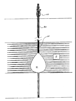
22 Figure 1 is a side cross-sectional view of an embodiment of the
23 present invention, illustrating a combustion cavity in a hydrocarbon
reservoir, the
6
CA 02690105 2010-01-14
1 cavity being created by downhole burner and formed for disseminating hot
2 combustion gases for forming a gaseous drive front and interacting with
water
3 injected uphole of the cavity for forming an additional steam drive front;
4 Figure 2A is a side quarter-sectional view of a wellhead for supporting
three tubing strings extending down a cased wellbore according to one
embodiment
6 of the present invention;
7 Figure 2B is a side quarter-sectional elevation of the three tubing
8 strings of Fig. 2A (casing omitted) and illustrating a main tubing string
supporting
9 the downhole burner at a burner interface assembly, the main tubing string
having
an intermediate and an inner tubing string disposed therein;
11 Figure 3 illustrates a quarter-sectional, perspective view across the
12 casing and three concentric tubing strings;
13 Figure 4 is a side quarter-sectional view of an embodiment of a
14 downhole burner sealed at a downhole end to a casing for fluidly connecting
a
casing annulus and the reservoir through perforations;
16 Figure 5 is a side, quarter-sectional view of the burner of Fig. 3 with the
17 casing omitted, and illustrating the fuel passageway, the oxygen passageway
and
18 the nozzle;
19 Figure 6 is a side, quarter-sectional view of the burner of Fig. 3 with the
casing and oxygen passageway omitted for illustrating the casing seal and an
21 embodiment of fuel passageway swirl vanes;
22 Figure 7A is a partial cross-sectional view of the nozzle and an
23 embodiment of a brush-type casing seal of Fig. 3 with the casing omitted;
7
CA 02690105 2010-01-14
1 Figure 7B illustrates an activated brush seal according to Fig. 7A and
2 showing the stack of flexible brush rings flexing when constrained by the
casing;
3 Figure 8 is a overhead plan view of one concentric brush ring of a
4 stack of concentric brush rings of a brush seal and an arrangement of spiral
slits and
fingers;
6 Figure 9 is a perspective view of two brush rings of the stack of
7 concentric brush rings according to Fig. 8 illustrating a rotational
offsetting of the
8 spiral slits for forming a tortuous, restrictive fluid path therethrough;
9 Figure 10 is a schematic representation a main tubing string, an
intermediate tubing latched within the bore of the main tubing string, and an
inner
11 tubing latched and terminated within the bore of the intermediate tubing,
three fluid
12 passageways created therein, the inner annulus being terminated at the
13 intermediate mandrel;
14 Figure 11 is a cross-sectional view of the burner interface assembly
illustrating the outer housing, the intermediate and inner mandrels, the
intermediate
16 and inner latch assemblies, and the backpressure valve assembly;
17 Figure 12 is a side quarter-sectional view of an uphole end of the
18 intermediate mandrel for illustrating termination of the inner and
intermediate tubing
19 and the inner mandrel having an inner tubing latch;
Figure 13 is a quarter-sectional and elevation view of a step of the
21 running in of an embodiment of the apparatus of the invention, more
particularly
22 illustrating the main tubing hanger, and downhole adjacent the reservoir, a
torque
23 anchor, outer housing, pup joint, burner housing, burner nozzle and casing
seal;
8
CA 02690105 2010-01-14
1 Figure 14A is a quarter-sectional and elevation view of a further step
2 according to Fig. 13, more particularly illustrating the insertion of the
intermediate
3 tubing string, hanging the tubing from an intermediate tubing hanger,
latching of the
4 intermediate mandrel and positioning of the oxygen passageway within the
burner
housing;
6 Figure 14B is a closeup of the burner interface assembly of Fig. 14A
7 for illustrating the intermediate tubing, the intermediate mandrel and the
oxygen
8 passageway;
9 Figure 15A is a quarter-sectional and elevation view of a further step
according to Fig. 13, more particularly illustrating the insertion of the
inner tubing
11 string, hanging the inner tubing from an inner tubing hanger, latching of
the inner
12 mandrel; and
13 Figure 15B is a closeup of the burner interface assembly of Fig. 15A
14 for illustrating the hanging the inner tubing from the inner tubing hanger,
the inner
tubing and the inner mandrel.
16
17 DETAILED DESCRIPTION OF THE INVENTION
18 As shown in Fig. 1, a thermal process utilizes a downhole production of
19 heat, steam and hot combustion gases (primarily CO, C02, and H20) to best
effect
for the recovery of residual or otherwise intractable hydrocarbons from a
21 hydrocarbon reservoir 10. A burner assembly 20 initially creates a
combustion
22 cavity 30 and then creates and sustains the creation of hot combustion
gases, such
23 as CO, C02, and H20. Addition of water to the reservoir 10 above the
combustion
9
CA 02690105 2010-01-14
1 cavity 30 results in the production of a steam drive front. The steam and
hot
2 combustion gases combine to create a steam and gaseous drive front.
3 With further reference to Figs. 1, 2B, 3, 4 and 13, apparatus for
4 implementing such a process comprises a burner assembly 20 at a downhole end
of
a main tubing string 40 and one or more additional tubing strings. The main
tubing
6 string 40 and other tubing strings form a plurality of discrete fluid
passageways for
7 supplying the burner assembly 20. As shown in Fig. 4, the downhole burner 60
is
8 terminated in an existing cased welibore adjacent casing perforations
accessing the
9 reservoir 10. The burner assembly 20 can comprise a burner interface
assembly 50
for fluidly connecting to the tubing strings, a downhole burner 60, and a
casing seal
11 70 for sealing a casing annulus 80 between the downhole burner 60 and a
casing 90
12 of the cased welibore. The casing annulus 80 is yet another passageway used
for
13 directing water from the casing annulus 80 to the reservoir 10.
14 As shown in Figs. 2A to 4, one approach is to suspend the burner
assembly 20 from a conventional sectional tubing string supported by a
conventional
16 tubing hanger 100 on a wellhead 110. The casing annulus 80 is formed
between the
17 casing 90 of the welibore and the main tubing string 40 and extends to the
annular
18 space between the casing 90 of the wellbore and the burner assembly 20.
19 An intermediate tubing string 120 having an intermediate bore, such as
an intermediate coil tubing string, is supported by an intermediate tubing
hanger 130
21 on the wellhead 110 and disposed within a bore of the main tubing string
40. An
22 intermediate annulus 140 is formed between the main tubing string 40 and
the
23 intermediate tubing string 120.
CA 02690105 2010-01-14
1 An inner tubing string 150, such as an inner coil tubing string, is
2 supported by an inner tubing hanger 160 on the wellhead 110 and is further
3 disposed within the intermediate bore of the intermediate tubing string 120,
forming
4 a inner annulus 170 therebetween. The inner tubing string 150 further has an
inner
bore 180.
6 The wellhead 110 and tubing hangers 100, 130, 160 can be any
7 appropriate wellhead and tubing hangers that are commonly available in the
8 industry, such as the thermal wellhead and tubing hangers commercially
available
9 from StreamFlo Industries, Ltd., located at Edmonton, Alberta, Canada. The
casing
annulus 80, the intermediate annulus 140, inner annulus 170, and the inner
bore 180
11 all define discrete passageways for supplying the burner assembly 20.
12 The casing 90 of the cased wellbore, main tubing string 40, the
13 intermediate tubing string 120 and the inner tubing string 150, creating
the four
14 discrete passageways, terminate at the burner interface assembly 50. The
casing
annulus 80 terminates at the downhole burner 60 for communication with the
16 reservoir 10. The inner annulus 170 terminates at the burner interface
assembly 50.
17 The two remaining discrete passageways, the intermediate annulus 140, and
inner
18 bore 180, all connect or terminate at the downhole burner 60.
19 In one embodiment, the downhole burner 60 implements at least two
fluid passageways for conducting fuel and oxidant for combustion. The oxidant
is a
21 source of oxygen, conventionally air, or more concentrated source such as a
purified
22 stream of oxygen. In a preferred embodiment, purified oxygen is used as the
11
CA 02690105 2010-01-14
1 oxidant instead of conventional air, as conventional air produces combustion
gases
2 having a substantial amount of gaseous nitrogen products.
3 The burner interface assembly 50 fluidly connects two of the discrete
4 passageways to two fluid passageways of the downhole burner 60. In one
arrangement, a third discrete passageway can be utilized as an isolating
6 passageway between the fuel and the oxygen for sensing or detecting leaks in
the
7 discrete passageways for the fuel and oxygen..
8 The downhole burner 60 comprises a burner housing 190 having a
9 downhole portion 200 for the mixing of fuel and oxygen. The burner housing
190
supports a high temperature casing seal 70 for sealing the casing annulus 80
from
11 the combustion cavity 30. The sealed casing annulus 80 can be used to
fluidly
12 communicate water down to the target zone, which is then injected into the
reservoir
13 10 for creating steam within the target zone, above the combustion cavity
30.
14 With reference to Figs. 2A, 2B, and 3, one embodiment of the present
invention comprises the burner assembly 20 fluidly connected to the main
tubing
16 string 40. A downhole burner 60 is positioned at a downhole portion of a
cased
17 portion of an injection well, the casing 90 being perforated into the
reservoir 10. The
18 main tubing string 40 extends downhole and has conduits or passageways for
19 conducting or transporting each of fuel, and oxygen, to the downhole burner
60. For
ease of installation, intermediate and inner tubing strings 120, 150 are
releasably
21 connected to the burner assembly 20.
12
CA 02690105 2010-01-14
1 The downhole components, or as part of the burner assembly 20, can
2 further comprise a torque anchor 210 to set the main tubing string 40 in the
casing
3 90.
4 In greater detail, and with reference to Figs. 3 to 6, the burner housing
190 is adapted at an uphole portion 220 for fluid communication with the
6 intermediate annulus 140 and inner bore 180. In one embodiment, the burner
7 housing 190 is fluidly connected to the intermediate annulus 140 and the
inner bore
8 180 through the burner interface assembly 50. The burner housing 190
comprises
9 two fluid passageways for fluidly communicating the fuel and oxygen.
As best shown in Figs. 5 and 6, the burner housing 190 comprises the
11 downhole portion or burner nozzle 200 for combustion of the fuel and oxygen
and an
12 uphole portion 220 defining the two fluid passageways for fluidly
communicating the
13 fuel and oxygen to the nozzle 200. The uphole portion 220 has a bore 230
and a
14 concentric conduit or tubing 240 extending therethrough for creating the
two fluid
passageways. A fuel passageway 250 is defined by the annular space formed
16 between the bore 230 and the concentric conduit 240. The concentric conduit
240
17 further has a bore defining an oxygen passageway 260.
18 The fuel passageway 250 is adapted to fluidly communicate with the
19 intermediate annulus 140, communicating fuel from the surface to the nozzle
200.
The bore 230 of the burner housing 190 and the fuel passageway 250 open into
the
21 nozzle 200 for injecting the fuel into the nozzle 200. The fuel passageway
250 can
22 further have fuel swirl vanes 270 for aiding in the mixing of the fuel and
oxygen.
13
CA 02690105 2010-01-14
1 The oxygen passageway 260 is in fluid communication with the inner
2 bore 180, communicating oxygen from the surface to the nozzle 200. The
oxygen
3 passageway 260 has an opening 280 at a downhole end for injecting oxygen
into the
4 nozzle 200. The oxygen passageway 260 can further have oxygen swirl vanes
(not
shown) for aiding in the mixing of the fuel and oxygen. The oxygen and fuel
mix for
6 combustion at the nozzle 200.
7 With reference to Fig. 5, as stated above, the fuel passageway 250
8 can further have fuel swirl vanes 270 for imparting a rotation to the fuel
being
9 injected into the nozzle 200. The oxygen passageway 260 can also have oxygen
swirl vanes for imparting a rotation, counter to the direction of the rotation
of the fuel,
11 for maximizing the mixing of the fuel and oxygen for increasing the
efficiency of the
12 combustion of the fuel and oxygen. In a preferred embodiment, the ratio of
swirl
13 velocity to axial flow velocity of either the fuel or oxygen is
substantially 1:2.
14 In an alternate embodiment, the opening 280 of the oxygen
passageway 260 can be fitted with a bluff body (not shown) to reduce the axial
16 momentum of the oxygen for stabilizing the combustion flame.
17 Further, in another alternate embodiment (not shown), the burner
18 housing 190 can have two side-by-side bores extending therethrough for
forming the
19 fuel passageway and the oxygen passageway. Each bore can have an opening at
a
downhole end for injecting the fuel and oxygen into the nozzle 200 for
combustion.
21 Conventional burner discharge arrangements can be employed
22 including utilizing a plurality of orifices and concentric discharges. The
nozzle 200
23 can be any open ended tubular structure that allows mixing and combustion
of the
14
CA 02690105 2010-01-14
1 fuel and oxygen. As shown, the nozzle 200 is a typical inverted truncated
frusto-
2 conical nozzle. The truncated apex is fluidly connected to the burner
housing 190
3 and the nozzle 200 extends radially outwardly towards a downhole end.
4 As shown in Figs. 4 and 6, the high temperature casing seal 70 can be
located on the downhole burner 60 to isolate the casing annulus 80 from the
6 combustion cavity 30. Accordingly, the casing seal 70 is generally located
low on
7 the downhole burner 60, such as between the downhole portion of the burner
8 housing or nozzle 200 and the casing 90. In alternate embodiments (not
shown),
9 the casing seal 70 can located between the uphole portion 220 of the burner
housing
190 and the casing 90.
11 Often, cased welibores have casing distortions or kinks which
12 introduce challenges to installation and tolerances for related seals to
the casing.
13 The casing distortions are an abrupt shifting of the casing axis resulting
in a casing
14 portion that is narrower than a nominal inner diameter of a typical casing.
The
passage of seals and other downhole tools are difficult at best if the nature
of the
16 seal is to initially comprise an outer diameter of seal which is larger
than the inner
17 diameter of casing and certainly greater than the distortion. Although
downhole
18 tools generally can be manufactured to have a small outer diameter to allow
them to
19 pass through a majority of distortions, seals generally can not. Seals
having small
outer diameter, although capable of passing through the distortions, are
unlikely to
21 fully seal against the casing downhole of the distortion where the casing
again has a
22 nominal inner diameter. Seals must also be able to withstand the extreme
heat
23 conditions created by a downhole burner when combusting the fuel and
oxygen.
CA 02690105 2010-01-14
1 With reference to Figs. 6 to 9, an embodiment of the casing seal 70 is
2 a brush-type seal comprising a plurality of flexible, concentric, metallic
brush rings
3 300 stacked one on top of another. As best shown in Figs. 6, 7A and 7B, the
brush
4 rings 300 are stacked one on top of another upon a circumferential stop
shoulder
310 at a downhole end of the nozzle 200. Spacer rings 320 can be provided to
6 alternate between the brush rings 300. The stack of brush rings 300 and
spacer
7 rings 320 is secured in place by a compression ring 330 exerting an axial
securing
8 force to sandwich the rings 300, 320 to the stop shoulder 310. A compression
nut
9 340 secures the compression ring 330.
As shown in Figs. 8 and 9, each seal ring 300 has a multiplicity of slits
11 350 that are formed radially inward from an outer circumference of the seal
ring 300
12 and which terminate before an inner diameter of the seal ring 300 for
forming a
13 plurality of flexible fingers 360. The fingers are separated at the outer
circumference
14 and connected at the inner diameter. An inner most radial extension of each
slit 350
defines the inner diameter of the multiplicity of slits 350 and is
substantially the same
16 as the outer diameter of the spacer rings 320. The plurality of fingers
360, flexing
17 from the inner diameter, provide dimensional variability through
flexibility for each
18 concentric seal ring 300.
19 Each slit 350 extends radially outwardly in a generally clockwise
direction as viewed looking downhole. This particular slit arrangement or
design is
21 advantageous when removing and pulling up the casing seal 70. In the event
that
22 the casing seal 70 becomes stuck, the clockwise slit arrangement allows the
casing
16
CA 02690105 2010-01-14
1 seal to be rotated in a counter-clockwise direction, thus decreasing the
outer
2 diameter of the casing seal 70, and allowing it to dislodge from the casing
90.
3 As shown in Fig. 9, each seal ring 300 can be rotationally indexed
4 relative to each adjacent seal ring 300. While enabling radial flexibility,
the slits 350
provide an avenue for fluids to leak therethrough. In order to minimize the
amount of
6 leaking of fluids through the slits 350, each seal ring 300 is rotated such
that the slits
7 350 of axially adjacent brush rings 300 are rotationally offset or
misaligned. To
8 further mitigate leakage through the slits 350, the plurality of concentric
brush rings
9 300 are stacked. Each finger 360 of one seal ring 300 overlaps each finger
360 of
an adjacent seal ring 300, for forming a tortuous axial path for restricting
flow of
11 casing annulus fluids therethrough.
12 Referring back to Fig. 7A, the brush seal 70 has an outer diameter
13 greater than a nominal inner diameter of a casing 90 in a cased wellbore as
14 indicated by the dashed line. The greater outer diameter defines the
effective
sealing diameter of a particular brush seal. Brush-type seals having differing
16 effective sealing diameters can be readily installed depending on the size
of the
17 casing 90 in the cased wellbore.
18 When the brush-type seal is run downhole, each finger 360 of each
19 seal ring 300 flexes uphole, reducing the overall outer diameter and
conforming to
the casing 90, while maintaining the effective sealing diameter. The reduction
of the
21 overall outer diameter of the brush rings 300 allow the brush seal 70 to
pass through
22 a cased wellbore during installation and pass by most casing distortions.
Upon
17
CA 02690105 2010-01-14
1 encountering a casing distortion, the ring fingers 360 of each concentric
seal ring
2 300 can elastically flex an additional amount to enable movement past the
distortion.
3 In an alternate embodiment, other casing seals might be employed
4 including a metallic inflatable packer, such as those now introduced by
Baker Oil
Tools, as presented in a paper entitled "Recent Metal-to-Metal Sealing
Technology
6 for Zonal Isolation Applications Demonstrates Potential for Use in Hostile
HP/HT
7 Environments", published as SPE 105854 in February 2007. Such inflatable
8 packers are small enough in diameter to also pass through casing distortions
and
9 may be able to withstand the extreme heat conditions created by the burner.
However, such packers can be damaged by thermal cycling and may not be
11 reusable.
12 For example, in a 7 inch (178 mm) casing having an inner diameter of
13 about 164 mm, a burner bottom hole assembly (BHA) fluidly connected to the
14 downhole end of a 3-1/2 inch (89 mm) tubing, can be placed in a cased
wellbore
having the typical casing distortions. The burner BHA, comprising the burner
16 interface assembly, pup joint, and downhole burner, had a total length of
about 5
17 feet (1524 mm). A 2-3/8 inch (60 mm) intermediate coil tubing was disposed
within
18 the 3-1/2 inch (89 mm) tubing, and a 1-'/4 inch (32 mm) inner coil tubing
was disposed
19 within the intermediate coil tubing. The burner interface assembly was
about 708
mm long and had an outer diameter of about 114 mm, while the burner housing
was
21 about 304 mm long with an outer diameter of about 93 mm. The brush seal had
an
22 outer diameter of about 164 mm and was installed on a nozzle having a
23 circumferential shoulder of about 120 mm. Each brush ring and spacer ring
had a
18
CA 02690105 2010-01-14
1 thickness of about 0.25 mm. The pup joint, tailored to this particular
example, was
2 about 508 mm long and had an outer diameter of about 2-7/8 inches (73 mm).
3 With reference to Figs. 3 and 10, the fluid passageways can be formed
4 by a series of tubing strings disposed in the bore of a larger tubing, or
sectional
tubing. Alternatively, two or more tubing strings might be arranged side-by-
side (not
6 shown). As shown in Fig. 3, the main tubing 40 is run down the cased
wellbore
7 forming the casing annulus 80 or a first casing annular fluid passageway
8 therebetween. The intermediate tubing string 120 is disposed concentrically
within
9 the bore of the main tubing string 40, forming the intermediate annulus 140
or a
second intermediate annular fluid passageway therebetween. The inner tubing
11 string 150 is further disposed concentrically within the intermediate bore
of the
12 intermediate tubing string 120 forming the inner annulus 170 or a third
inner annular
13 fluid passageway therebetween. The bore of the inner tubing string 150
further
14 defines the inner bore 180 or a fourth, inner bore fluid passageway.
Those skilled in the art would understand that although the
16 intermediate tubing string 120 is concentrically disposed with the bore of
the main
17 tubing 40, the intermediate tubing string 120 may not remain concentrically
aligned
18 within the bore of the main tubing 40 as the intermediate tubing string 120
is run
19 downhole. Similarly, the inner tubing string 150, although concentrically
disposed in
the intermediate bore of the intermediate tubing string 120 may not remain
21 concentrically aligned as the inner tubing string 150 is run downhole.
22 In a basic form, two passageways are used for providing fuel and
23 oxygen to the burner. A third passageway can be provided for isolating the
fuel and
19
CA 02690105 2010-01-14
1 oxygen, and even more favourably for acting as a sensing passageway for
2 determining development of a leak therebetween.
3 With reference to Figs. 10 to 12, in one embodiment, a burner interface
4 assembly 50 fluidly connects three passageways of the main tubing 40 to the
fuel
and oxygen passageways 250, 260 of the downhole burner 60. The burner
interface
6 assembly 50 can comprise an outer housing 400 secured intermediate or at the
7 downhole end of the main tubing string 40, an intermediate mandrel 410 at a
8 downhole end of the intermediate tubing string 120, and an inner mandrel 420
at a
9 downhole end of the inner tubing string 150.
The outer housing 400 has a bore which is adapted to releaseably
11 connect with the intermediate mandrel 410. The intermediate mandrel 410 has
an
12 uphole portion 430 having a bore which is adapted to releaseably connect
with the
13 inner mandrel 420.
14 In greater detail, and with reference to Fig. 11, the outer housing 400
has a bore, an uphole end 440 and a downhole end 450. The uphole end 440 is
16 adapted to fluidly connect to the main tubing string (not shown) and the
downhole
17 end 450 is adapted to fluidly connect to a pup joint which supports the
downhole
18 burner (not shown).
19 With reference to Figs. 10 and 11, the intermediate mandrel 410 is fit
within the bore of the outer housing 400 forming the intermediate annulus 140
21 therebetween. The intermediate mandrel 410, releaseably connected to the
outer
22 housing 400 at an intermediate latch assembly 470, has an uphole portion
430
23 which is adapted to fluidly connect to the intermediate tubing string 120.
The uphole
CA 02690105 2010-01-14
1 portion 430 further has a bore for releaseably connecting to the inner
mandrel 420.
2 In one embodiment, the uphole portion 430 is an inner latch housing.
3 The bore of the outer housing 400 has an inner surface 480 for forming
4 a first intermediate latch 470A. The first intermediate latch 470A is formed
adjacent
a downhole end of the outer housing 400.
6 Further, the intermediate mandrel 410 has a second intermediate latch
7 470B formed at its downhole end. The second intermediate latch 470B is
adapted to
8 releaseably connect to the complementary first intermediate latch 470A to
form the
9 intermediate latch assembly 470.
With reference to Figs. 10 and 12, the inner mandrel 420 is fit within
11 the bore of the inner latch housing 430 and releasably connects with the
12 intermediate mandrel 410 at an inner latch assembly 490. Similar to the
13 intermediate latch assembly 470, the inner latch assembly 490 comprises a
first
14 inner latch 490A and a complementary second inner latch 490B.
As shown, the intermediate mandrel 410 is fit within the bore of the
16 outer housing 400 for latching at the intermediate latch assembly 470 and
sealing at
17 a first seal 500 therebetween. The inner mandrel 420 is fit within the bore
of the
18 inner latch housing 430 for latching at the inner latch assembly 490 and
sealing at a
19 second seal 510 therebetween.
The intermediate annulus 140 is contiguous with an annular space
21 between the outer housing 400 and the intermediate mandrel 410 and is in
fluid
22 communication with the fuel passageway 250 of the downhole burner 60. The
inner
23 bore 180 is contiguous with a bore of the inner mandrel 420 and is in fluid
21
CA 02690105 2010-01-14
1 communication with the oxygen passageway 260 of the downhole burner 60. In
this
2 embodiment, the inner annulus 170 happens to terminate sealably at the
second
3 seal 510 for isolating the intermediate annulus 140 from the inner bore 180.
4 The sealed inner annulus 170 isolates the intermediate annulus 140
from the inner bore 180. This separation of the two discrete passageways
provides
6 a safety measure, ensuring that the fuel and the oxygen are separated by a
buffer.
7 In one embodiment, the sealed inner annulus 170 is also a sensing annulus
for
8 detecting leakage in the transport of the fuel and the oxygen. The sealed
inner
9 annulus 170 can be maintained in a vacuum or other pressure and is monitored
for
determining change in pressure indicative of a leak in either the intermediate
11 annulus 140 or the inner bore 180.
12 The intermediate latch assembly 470 can be any suitable releasable
13 latch used in the industry, but in a preferred embodiment, the intermediate
latch
14 assembly is a type of latch assembly disclosed and claimed in US Patent
Serial
Number 6,978,830, issued on December 27, 2005, to MSI Machineering Solutions,
16 Inc., located in Providenciales, Turks and Caicos.
17 Similar to the intermediate latch assembly 470, the inner latch
18 assembly 490 can be any suitable latch assembly used in the industry,
including that
19 disclosed and claimed in the aforementioned US Patent 6,978,830.
As best shown in Fig. 12, an uphole end of the inner latch housing 430
21 is fit with a third seal 520 for sealing and isolating the intermediate
annulus 140 from
22 the inner annulus 170. The inner latch housing 430 further has a second
seal 510
23 for sealing and isolating the inner annulus 170 from the inner bore 180.
22
CA 02690105 2010-01-14
1 For redundancy purposes, and to ensure sealing and isolating of the
2 three discrete passageways, the first, second, and third seals 500, 510, 520
can be
3 a plurality of individual seals in a stacked arrangement.
4 For greater safety and control of the fuel and oxygen passageways,
and in a particular embodiment, the intermediate mandrel 410 can further
comprise
6 a backpressure valve assembly 600 for controlling the flow of the fuel and
oxygen.
7 Fuel is forced from the intermediate annulus 140 through the backpressure
valve
8 assembly by the first seal 500.
9 The backpressure valve assembly 600 comprises two fluid bypass
passageways, each having a backpressure valve. The fluid bypass passageways
11 bypass the first seal 500. A first bypass passageway 610, having a first
12 backpressure valve 620, is in fluid communication with the intermediate
annulus 140
13 for transporting the fuel from the main tubing string 40 to the fuel
passageway 250 of
14 the downhole burner 60. A second bypass passageway 630, having a second
backpressure valve 640, is in fluid communication with the inner bore 180 for
16 transporting the oxygen to the oxygen passageway 260 of the downhole burner
60.
17 Each of the backpressure valves comprises a ball 620A, 640A and a
18 spring 620B, 640B, biased to apply a constant closing force on the ball,
ensuring
19 that the ball is sealingly fit within a ball seat 650A, 650B. The constant
closing force
is greater than the force applied by the differential fluid pressure between
the static
21 fluid pressure above the backpressure valves 620, 640 and a reservoir
pressure
22 below the backpressure valves 620, 640. For either the fuel and/or oxygen
to flow
23 pass the backpressure valves 620, 640, the injection pressure of the fuel
or oxygen
23
CA 02690105 2010-01-14
1 must exert enough force to overcome the combined forces of the spring 620B,
640B
2 and the reservoir pressure.
3 In one embodiment, the closing force biasing the ball of the
4 backpressure valves 620, 640 is based upon a differential pressure of 200
psi. In
this embodiment, the injection pressure of both the fuel and oxygen must be
6 sufficient to exert sufficient pressure to overcome the combined forces of
the closing
7 force and the force exerted by the reservoir pressure.
8 The injection pressure of the fuel or oxygen does not exceed the
9 fracturing pressure of the particular target zone.
11 IN OPERATION
12 In one embodiment, a combustion chamber 30 is formed by melting a
13 target zone at a temperature sufficient enough to melt the hydrocarbon
reservoir 10
14 at the target zone. Thereafter, a steady state combustion is maintained for
sustaining a sub-stoichiometric combustion of the fuel and oxygen for
producing hot
16 combustion gases (primarily CO, 002, and H2O) which enter and permeate
through
17 the reservoir 10. The hot combustion gases create a gaseous drive front and
heat
18 the reservoir 10 adjacent the combustion cavity 30 and the wellbore.
19 Addition of water to the reservoir 10 along the casing annulus 80
above the combustion chamber 30 injects water into an upper portion of the
21 reservoir 10 adjacent the wellbore for lateral permeation through the
reservoir 10.
22 The lateral movement of the injected water cools the wellbore from the heat
of the
23 hot combustion gases and minimizes heat loss to the formation adjacent the
24
CA 02690105 2010-01-14
1 wellbore. The water further laterally permeates through the reservoir 10 and
2 converts into steam. The steam and the hot combustion gases in the reservoir
10
3 form a steam and gaseous drive front.
4 In more detail and referring again to Figs. 1, and 13 - 15B, an injection
well is cased and perforated at a target zone of the reservoir 10.
6 A packer is set and a suitable depth of thermal cement is placed below
7 the target zone. The thermal cement protects the packer from the downhole
burner
8 60.
9 Referring to Fig. 13, a first main tubing hanger 100 is affixed to a
wellhead 110. A burner bottom hole assembly (burner BHA) 700 comprising a
11 torque anchor 210, the outer housing 400 of the burner interface assembly
50, a pup
12 joint 710, and the downhole burner 60 are fluidly connected to a downhole
end of a
13 main tubing string 40. The burner BHA 700 is run downhole to a depth for
14 positioning the downhole burner 60 within a target zone. In one embodiment,
the
downhole burner 60 is positioned at about the midpoint of the target zone.
Once in
16 position, the main tubing string 40 is rotated to set the torque anchor 210
and the
17 main tubing string 40 is hung from the main tubing hanger 100.
18 As shown in Figs. 1 and 3, the main tubing string 40 and the casing 90
19 of the wellbore form a casing annulus 80 therebetween. The casing seal 70
between the burner housing 190 and the casing 90 seals the casing annulus 80.
21 Referring to Fig. 14B, an intermediate tubing hanger 130 is supported
22 on the main tubing hanger 100. With reference to Figs. 14A and 14B, the
23 intermediate mandrel 410 is fluidly connected to a downhole end of the
intermediate
CA 02690105 2010-01-14
1 tubing string 120, and the concentric tubing 240 defining the oxygen
passageway
2 260 extends downhole from the intermediate mandrel 410. As shown in Fig.
14B,
3 the intermediate tubing string 120 is run downhole within the bore of the
main tubing
4 string 40. The intermediate mandrel 410 is run downhole until it is tagged
with the
outer housing 400 of the burner interface assembly 50. Tagging the
intermediate
6 mandrel 410 to the outer housing 400 involves releaseably connecting the
outer
7 housing 400 to the intermediate mandrel 410 at the intermediate latch
assembly
8 470, forming the intermediate annulus 140 therebetween. The intermediate
tubing
9 string 120 is pulled uphole to stretch the intermediate tubing 120 and
remove any
slack. The intermediate tubing string 120 is hung by the intermediate tubing
hanger
11 130 and then cut to an appropriate length.
12 With reference to Fig. 15A, an inner tubing hanger 160 is supported on
13 the intermediate tubing hanger 130. The inner mandrel 420 of the burner
interface
14 assembly 50 is fluidly connected to a downhole end of the inner tubing
string 150,
and run downhole within the intermediate bore of the intermediate tubing
string 120.
16 The inner tubing string 150 is run downhole until the inner mandrel 420
tags the
17 intermediate mandrel 410 forming the inner annulus 170. Tagging the inner
mandrel
18 420 to the intermediate mandrel 410 involves releaseably connecting the
inner
19 mandrel 420 to the intermediate mandrel 410 at the inner latch assembly
490. The
inner tubing 150 is pulled uphole to stretch the inner tubing 150, hung by the
inner
21 tubing hanger 160 and then cut to an appropriate length. The bore of the
inner
22 tubing string 150 defines the inner bore 180.
26
CA 02690105 2010-01-14
1 The intermediate annulus 140 can be fluidly connected to a source of
2 fuel, and the inner bore 180 can be fluidly connected to a source of
oxidant, such as
3 oxygen. The inner annulus 170 is sealed and is monitored. Any changes with
the
4 pressure within the sealed inner annulus 170 are indicative of a leak in
either the
intermediate annulus 140 or the inner bore 180.
6 A further utility of the backpressure valve assembly is to assure
7 successful latching and continuity of the intermediate and inner tubing
string at the
8 burner interface assembly, an inability of the either passageway to retain
pressure
9 up to the opening pressure of the valves being indicative of a problem in
the
connections of one form or another.
11 The fuel can be delivered down the intermediate annulus 140 passing
12 through the first bypass passageway 610 and first backpressure valve 620
and to
13 the fuel passageway 250. Similarly, oxygen can be injected down the inner
bore
14 180, through the second bypass passageway 630 and the second backpressure
valve 640 to the oxygen passageway 260. Both the fuel and oxygen enter the
16 nozzle 200 for combustion. The first and second backpressure valves 620,
640
17 creates a backpressure greater than that static head to surface pressure,
ensuring
18 that the flow of the fuel and oxygen can be controlled from the surface by
controlling
19 the flow rate of the fuel and oxygen. If the flow rate of the fuel or
oxygen does not
create enough pressure to overcome the pressure exerted by the closing force
of the
21 backpressure valve spring 620B, 640B and the reservoir pressure, fuel and
oxygen
22 cannot pass the first and second backpressure valves 620, 640.
27
CA 02690105 2010-01-14
1 After the burner assembly 20 is positioned within the target zone, the
2 reservoir 10 can be initially flooded with water. Water is injected down the
casing
3 annulus 80 to enter the reservoir 10 through the perforations for increasing
the
4 reservoir pressure adjacent the wellbore. The fuel is then injected
downhole. After
a sufficient amount of time to ensure that the fuel has entered the target
zone
6 downhole, the fuel is doped with an accelerant, a pyrophoric compound such
as
7 triethylborane or silane, sufficient for igniting the fuel. Oxygen is
injected to light off
8 the downhole burner 60. The accelerant is discontinued to create a stable
flame for
9 combustion. A stable flame can be maintained by controlling the rate of the
fuel and
oxygen. The fuel and oxygen are controlled to combust at a temperature to
create a
11 combustion cavity 30 sufficient to melt or otherwise form a cavity 30.
12 In one embodiment, the downhole burner 60 can be lit off and form a
13 minimum stable flame temperature of about 2800 C. At such a temperature,
it is
14 believed that the casing 90 and the surrounding reservoir 10 downhole of
the burner
60 would melt, forming the combustion cavity 30. As the combustion cavity 30
16 expands, molten material will flow and pool at a bottom of the combustion
cavity 30
17 above the thermal cement for forming an impermeable glassy bottom. Further,
the
18 heat from the flame continues to be transferred to the lateral walls by a
combination
19 of radiant heat transfer and hot combustion gases permeating into the
reservoir 10.
Melting and enlargement of the combustion cavity 30 ceases when the combustion
21 cavity 30 is sufficiently large enough that the heat transfer from the
combustion is
22 below the melting point of the reservoir 10. The lateral walls of the
combustion
23 cavity 30 remain porous and permeable, perhaps in a sintered state.
28
CA 02690105 2010-01-14
1 Once the combustion cavity 30 has been formed, the fuel and oxygen
2 are controlled to continue steady state combustion for creating and
sustaining hot
3 combustion gases for flowing and permeating into the target zone.
4 Further, the steady state combustion of the fuel and oxygen is also
under sub-stoichiometric conditions, limiting the amount of oxygen available
for
6 combusting with the fuel. The limited amount of available oxygen ensures
that there
7 is no excess oxygen available for flowing into the reservoir 10. Excess
oxygen
8 flowing into the reservoir 10 may result in additional combustion within the
reservoir
9 10 and result in some coking therein.
Water is delivered down the casing annulus 80. The casing seal 70
11 directs the water out the perforations and into the target zone
concurrently as hot
12 combustion gases are created and sustained at steady state. The injected
water
13 and hot combustion gases in the target zone interact to form a drive front
comprising
14 steam and hot combustion gases.
The present process further protects the reservoir 10 from permeability
16 degradation due to chloride scaling by keeping the chlorides in solution.
Most
17 chloride scaling is caused by introducing water with a dissimilar ion
charge during
18 water flooding. Increasing temperature and/or pressure typically improves
solubility
19 of chlorides. The risks of chlorides deposition are reduced as both
temperature and
pressure increase with the introduction of heat and CO2 (from the hot
combustion
21 gases). Higher CO2 concentrations in formed emulsion increases carbonate
22 solubility. The process can be operated to continually produce incremental
CO2,
23 gradually increasing concentrations as the flood progresses.
29
CA 02690105 2010-01-14
1 Risk of chloride scaling is further mitigated by maintaining an 80%
2 steam quality downhole which keeps chlorides in solution. Untreated produced
3 water typically contains upwards of 50,000 ppm of total dissolved solids,
which is
4 typically treated prior to being passed through boilers for conventional
stem flood
processes. Control of the mass and heat balance of the combustion process
6 permits management of the steam generation in the target zone to be at about
80%
7 steam quality. The lower steam quality ensures that there is a sufficient
water phase
8 to keep all dissolved solids in solution and treatment of the produced water
is not
9 required.
In an alternate embodiment, fuel can be injected downhole through the
11 inner bore 180, while the oxygen can be injected down through the
intermediate
12 annulus 140.
13 Further, in an alternate embodiment, where regulation may prohibit
14 injection of fluid down the casing annulus 80, water can be injected down
one o the
other passageways. For example, water could be injected down the intermediate
16 annulus 140 for injection at the burner assembly for communication with the
17 hydrocarbon reservoir. In such an embodiment, the inner annulus 170 can be
used
18 to inject fuel or oxygen, instead of being used as a sensing annulus for
detecting
19 leaks, oxygen or fuel could continue to be injected down in the inner bore
180.
Further, as those skilled in the art would understand, the intermediate
annulus 140
21 would have a water injection port in the burner assembly and placed in
fluid
22 communication with the reservoir to allow the injected water to flow into
and
23 permeate through the reservoir and a flow through packer can be used to
isolate the
CA 02690105 2010-01-14
1 burner assembly 20. One approach is to locate a flow-through packer at about
the
2 burner assembly for sealing the casing annulus above the water injection
port.
3 Water injected from the intermediate annulus would exit from the water
injection port
4 and into an injection annulus formed in the casing annulus between the
packer and
the casing seal.
6 Further still, yet, in a further alternate embodiment, the inner tubing
7 string 150 can be eliminated such as to reduce costs. In such an embodiment,
the
8 main tubing string 40 can be disposed within the casing 90 forming the
casing
9 annulus 80, and the intermediate tubing string 120 can be disposed in the
main
tubing string 40 forming the intermediate annulus 140. The intermediate tubing
11 string 120 would have a bore forming the inner bore 180. This embodiment
would
12 not have the inner annulus 170 to serve as a sensing annulus for detecting
leaks in
13 the intermediate annulus 140 and/or the inner bore 180.
14
31