Note: Descriptions are shown in the official language in which they were submitted.
CA 02690148 2009-12-08
WO 2008/154003 PCT/US2008/007223
SYSTEM AND METHOD FOR INTEGRATING VIDEO
ANALYTICS AND DATA ANALYTICS/MINING
FIELD OF THE INVENTION
The present invention relates generally to a system and method for analyzing
video and more particularly to a system and method for integrating video
analytics and
data analytics/data mining that exploit the strengths of both video and data
analytics.
BACKGROUND OF THE INVENTION
The use of video surveillance and analysis has become commonplace in deterring
shoplifting and theft in retail stores. However, in retail and other settings
there is often
too much data and video being collected from security and business operations
for
humans to manage effectively and efficiently. With tighter budgets and
pressures on
limiting headcount, the burdens are even greater. Businesses need tools to
filter and
mine the data so they can determine exceptions, patterns and/or anomalistic
behavior. In
addition, there are more sophisticated threats of collusion, ranging from
cashier
"sweethearting" transactions (bypassing scanners) for their own or a
customer's benefit,
to organized crime groups which work together across multiple incidences and
multiple
sites.
Some have tried to address and manage these problems from a business
operations standpoint with solutions that are based on analyzing the data
available from
store systems, such as the point of sale, to identify patterns of abnormal
behavior that
indicate areas of concern. Improvements to these solutions include having
these patterns
trigger video clips from the video surveillance system that provide visual
verification of
the situation. Others have approached the problem from a security standpoint,
using
0
CA 02690148 2009-12-08
WO 2008/154003 PCT/US2008/007223
computer algorithms to analyze the video from video surveillance systems, so
that that
some level of abnormal behavior can be detected visually in the scene
independent of
other triggers and used to implement strategies in business operations.
This business-data-alone approach fails for several reasons. The data
characterizing the situation may not be available because the store system may
have been
bypassed. Also, the data system tends to be post event mining, which limits
its ability to
handle real time/time sensitive alerts and notification. Given the data
systems'
limitations described above and the dependency of the video clip playback on
the data
trigger, this enhancement has failed also. The stand alone analysis of the
video is
problematic because it can be prone to false alarms or inadequate accuracy
levels to
make it reliable. Also these arrangements tend to require event
configuration/definition
of rules to detect the anomalies and these patterns may not be understood
ahead of time.
Accordingly, what is needed is a system and method for integrating video
analytics and data analytics/data mining that exploits the strengths of both
video and data
analytics to compensate for the limitations with previous solutions. What is
also needed
is integration software that is able to provide business and operational
intelligence to the
operation of facility entry/exit points, sales and service points, and
throughout the
interior and exterior.
1
CA 02690148 2009-12-08
WO 2008/154003 PCT/US2008/007223
SUMMARY OF THE INVENTION
The present invention advantageously provides a method and system to integrate
video analytics techniques with data analytics techniques to more accurately
identify
potentially suspicious behavior and events requiring attention of management
personnel.
Generally speaking, the present invention provides a method and system for
monitoring
facilities, such as retail stores or warehouses, using data collected at point
of sale
registers to more accurately recognized objects and events detected
simultaneously
through a video monitoring system.
One aspect of the present invention includes a method for detecting potential
suspicious behavior in a monitored facility. Video content of an activity
occurring at the
monitored facility and transaction data relating to a transaction processed at
a point of
transaction terminal are collected. The video content is correlated with the
transaction
data to produce correlated data. A set of user-defined rules are applied to
the correlated
data. Responsive to identifying a match between the correlated data and at
least one rule
of the set of user-defined rules, the transaction is determined to be
potentially suspicious.
Another aspect of the present invention includes a method of automatically
identifying activities occurring at a monitored facility. Video content of
activity
occurring at the monitored facility is collected. The video content is
analyzed using
object recognition techniques by applying a set of video analytics rules to
the collected
video information. Transaction data relating to one or more transactions
processed by at
least one point of transaction terminal within the sales facility is also
collected. In
response to determining that the video content conforms to at least one video
analytics
rule of the set of video analytics rules, the video content is correlated with
the transaction
data to provide correlated transaction data.
2
CA 02690148 2009-12-08
WO 2008/154003 PCT/US2008/007223
In accordance with another aspect of the present invention, a system for
analyzing activities occurring at a monitored facility includes a video
analytics system, a
data analytics system, and an integration server. The integration server is
communicatively coupled to the video analytics system and the data analytics
system.
The monitored facility includes at least one point of sale register. The video
analytics
system collects video content of activities occurring at the monitored
facility. The data
analytics system collects transaction data relating to one or more
transactions processed
by the at least one point of transaction terminal. The integration server
correlates the
video content to the transaction data to produce correlated data. The
integration server
also applies a set of user-defined rules to the correlated data and identifies
a match
between the correlated data and at least one rule of the set of user-defined
rules.
3
CA 02690148 2009-12-08
WO 2008/154003 PCT/US2008/007223
BRIEF DESCRIPTION OF THE DRAWINGS
A more complete understanding of the present invention, and the attendant
advantages and features thereof, will be more readily understood by reference
to the
following detailed description when considered in conjunction with the
accompanying
drawings wherein:
FIG. 1 is a block diagram of an exemplary video and data analytic system
constructed in accordance with the principles of the present invention;
FIG. 2 is a block diagram of exemplary video and data monitoring points
constructed in accordance with the principles of the present invention;
FIG. 3 is a flowchart of an exemplary return transaction process performed
according to the principles of the present invention;
FIG. 4 is a flowchart of an exemplary cash void transaction process performed
according to the principles of the present invention;
FIG. 5 is a flowchart of an exemplary customer counting process performed
according to the principles of the present invention;
FIG. 6 is a flowchart of an exemplary process to automatically link
transactional
exceptions to indexed video performed according to the principles of the
present
invention;
FIG. 7 is a flowchart of an exemplary line duration measuring process
performed
according to the principles of the present invention;
FIG. 8 is a flowchart of an exemplary cash drawer opening as detected by video
analytics without transactions detection process performed according to the
principles of
the present invention;
4
CA 02690148 2009-12-08
WO 2008/154003 PCT/US2008/007223
FIG. 9 is a flowchart of an exemplary process to set up point of sale ("POS")
rules and generate exceptions performed according to the principles of the
present
invention;
FIG. 10 is a flowchart of an exemplary process to set up user-definable video
rules and generate alerts performed according to the principles of the present
invention;
FIG. 11 is a flowchart of an exemplary process to set up user-definable store
data
and video rules combinations performed according to the principles of the
present
invention; and
FIG. 12 is a flowchart of an exemplary reporting process performed according
to
the principles of the present invention.
5
CA 02690148 2009-12-08
WO 2008/154003 PCT/US2008/007223
DETAILED DESCRIPTION OF THE INVENTION
Before describing in detail exemplary embodiments that are in accordance with
the present invention, it is noted that the embodiments reside primarily in
combinations
of apparatus components and processing steps related to implementing a system
and
method for analyzing video to determine the presence of an alarm condition by
integrating video analytics with data analytics/data mining techniques.
Accordingly, the
system and method components have been represented where appropriate by
conventional symbols in the drawings, showing only those specific details that
are
pertinent to understanding the embodiments of the present invention so as not
to obscure
the disclosure with details that will be readily apparent to those of ordinary
skill in the art
having the benefit of the description herein.
As used herein, relational terms, such as "first" and "second," "top" and
"bottom," and the like, may be used solely to distinguish one entity or
element from
another entity or element without necessarily requiring or implying any
physical or
logical relationship or order between such entities or elements.
One embodiment of the present invention advantageously provides a method and
system for analyzing video using a combination of video analytics and data
analytics/data mining techniques. In one embodiment, the invention may include
software consisting of user interfaces, e.g., Client/Browser, management and
analysis
components, and reporting capabilities. A video system with embedded analytics
at the
edge, video storage at a digital video recorder ("DVR") or other storage
device, and retail
transaction data devices may also be included.
In another embodiment, a user interface allows users to define the
configurations
and rules, pre-event, as well as conducting the mining of the data and video,
after the
6
CA 02690148 2009-12-08
WO 2008/154003 PCT/US2008/007223
fact. The video and data systems may be networked together and communicate via
database transmissions and queries as well as Application Programming
Interfaces. The
video and data analysis nodes may have the ability to process their analysis
in an
embedded, distributed manner, and transfer processed meta-data to the system
databases.
An extremely versatile embodiment of the present invention enables the
addition
of new pre-packaged and customer defined rules and measurements of operational
metrics called Key Performance Indicators ("KPIs"). By understanding the
problems and
opportunities with customers, the system may be used to define use cases that
are the
basis for generating the enabling rules and KPIs.
The system may be programmable to trigger alerts in real time, as well as mine
patterns of data and behavior after the fact, and combine both sources of
information so
to enhance the ability to address more complex and a wide range of use cases.
The
system may also be programmable to combine the triggers from video analysis
and data
analysis in the following comprehensive combinations: Data Analytics Trigger-
Video
verification, Video Analytics Trigger-Data Verification, Data Analytics
Trigger-Video
Analytics Verification, Video Analytics Trigger-Data Analytics Verification.
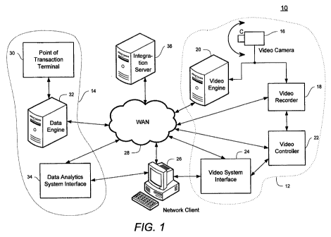
Referring now to the drawing figures in which like reference designators refer
to
like elements, there is shown in FIG. 1 an exemplary business intelligence
system 10 for
integrating video analytics and data analytics/data mining that exploits the
strengths of
both video and data analytics constructed in accordance with the principles of
the present
invention. The business intelligence system 10 may be structured to support
enterprise-
wide video solutions and broader use cases across retail operations.
The business intelligence system 10 combines a video analytics subsystem 12
with a data analytics subsystem 14 to model and detect suspicious activities
and
7
CA 02690148 2009-12-08
WO 2008/154003 PCT/US2008/007223
store/warehouse management events. The video analytics subsystem 12 may
include one
or more video cameras 16 (one shown), a video recorder 18, a video engine 20,
a video
controller 22, and a video system interface 24. The video camera 16 captures
images of
activity within a local viewing area and transfers the images to the video
recorder 18
and/or the video engine 20. The video recorder 18 may time-stamp and store the
captured images for later recall. The video engine 20 performs object
recognition/detection functions on the captured images to determine whether
images
captured by the video camera 16 meet conditions determined according to preset
rules.
Note that the function of the video engine 20 may be embedded in the video
camera 16
or other edge devices to allow processing of live video in addition to video
stored in the
video recorder 18. Additionally, time-stamping may also be performed by the
video
camera 16 or some other intermediate device. The video controller 22 controls
the basic
configuration of the video system, such as which video cameras 16 are active,
the pan,
tilt, angle, and zoom settings for each video camera 16, playback of requested
video
segments, etc. The video system interface 24 allows a user to set the rules
and
conditions for the video analytics server 20 and to choose specific video
segments for
playback.
Each component of the video analytics subsystem 12 may be directly coupled to
other components in the video analytics subsystem 12 at a local level.
Alternatively
and/or additionally, each component of the video analytics subsystem 12 may be
linked
to other components in the video analytics subsystem 12, the data analytics
subsystem
14, a network client 26, and/or other locations through a local-area network
("LAN")
(not shown) or wide-area network ("WAN") 28. Additionally, components of the
video
analytics subsystem 12 may be co-located or embedded within other components
of the
system 10. For example, the video system interface 24 may be implemented on
the
8
CA 02690148 2009-12-08
WO 2008/154003 PCT/US2008/007223
network client 26 as a web browser or a plug-in to existing data analytic
and/or video
software application.
The data analytics subsystem 14 includes a point of transaction termina130 for
collecting information relating to transactions within the monitored facility.
The point of
transaction termina130 may be a point of sale ("POS") register for collecting
information
relating to sales transactions conducted upon check-out. The point of
transaction
terminal 30 may include a communication interface for transmitting data with a
data
engine 32. The data engine 32 receives data concerning transactions completed,
initiated
or voided from one or more POS registers 30. The data analytics server 32
analyzes the
transaction data to determine if any transactions or group of transactions
meet conditions
determined according to preset rules as well as post event mining. The data
analytics
system interface 24 allows a user to set the rules and conditions for the data
engine 32
and to generate and view reports.
An integration server 36 combines elements of the video engine 20 and the data
engine 32 to correlate transaction events occurring at a point of transaction
termina130
with the recognition of objects detected by the video engine 20. The
integration server
36 may contain the video engine 20 and/or the data engine 32. Additionally,
data
analytics system interface 24 and the video system interface 24 may be
combined into a
single user interface (i.e., a dashboard) located at the network client 26.
Using the
dashboard, a user may combine one or more rules from the video analytics
system 12
with one or more rules from the data analytics system 14 to create a set of
rules for the
integration server 36 to determine precisely when very specific events occur.
Additionally, the system 10 may include a dashboard for each user type to
allow access
to only the views and reports that are of importance to their operational
needs.
9
CA 02690148 2009-12-08
WO 2008/154003 PCT/US2008/007223
The integration server 36 may be stand-alone or could reside on any
application
server. The integration server 36 for real time events could also be located
at a central
corporate level, either on the same hardware server as the data engine 32, or
on a
dedicated application server. The business intelligence system 10 should be
able to sync
time across all components.
The business intelligence system 10 may be implemented at local stores /
locations, at a
central corporate office, or a combination thereof connected through the wide-
area
network 28. The wide area network 16 may include the Internet, intranet, or
other
communication network. Although the communication network is pictured in FIG.
1 as
being a WAN, the principles of the present invention may also apply to other
forms of
communication networks, such as personal area networks ("PANs"), local area
networks
("LANs"), campus area networks ("CANs"), metropolitan area networks ("MANs"),
etc.
While the overall system 10 might be very complex, daily usage is extremely
user-friendly and intuitive. The system 10 advantageously provides an easy to
use video
system interface 24, data analytics system interface 34, and reporting
packages to
analyze data and view live and stored video that supports alerts and patterns.
Referring now to FIG. 2, a layout of an exemplary local retail facility 38 is
shown
which details potential video monitoring locations and data collection sites
in accordance
with the principles of the present invention. Although FIG. 2 shows a retail
facility, the
invention is not limited to such. It is contemplated that any monitored
facility can be
implemented and supported by the present invention, such as a warehouse or
other
location where merchandise or assets enters or leaves. The system 10 is
programmable
and is capable of providing business and operational intelligence to operation
facility
entry/exit points 40, points of sales (i.e., transactions) such as check-out
lines 42 or
CA 02690148 2009-12-08
WO 2008/154003 PCT/US2008/007223
customer service portals 44, service points 46, and points of selection 48
throughout the
interior and exterior of the monitored facility.
In FIG. 3, an exemplary operational flowchart is provided that describes steps
performed
in determining that a return transaction has transpired without the presence
of an actual
customer. In one embodiment, the process allows store managers or Loss
Prevention
("LP") professionals to monitor in real time when returns happen while no
customer is
present in front of POS counters. At least one video camera 16 should be
monitoring the
area surrounding a given POS register 30. When a return transaction is
processed at the
POS register 30 (step S 100), the data engine 32 receives the POS data (step S
102)
regarding the return transaction. The data may include, for example, an
identifier for the
POS register, the type of transaction, the time of transaction, the name or
other identifier
of the employee performing the transaction, the amount of the transaction,
etc. The data
engine 32 requests a visual verification from the video engine 20 (step S
104).
The video engine 20 attempts to count the number of customers present in front
of the POS register (step S 106). If the video engine 20 is unable to count
the customers,
the transaction is flagged as "customer count unknown" (step S 108). For
example certain
environmental conditions, such as sudden lighting changes, very dim lighting,
poor video
quality, intense glare in the image, camera motion may prevent the video
engine 20 from
being able to determine an accurate customer count. All transactions flagged
as
"customer count unknown" may constitute suspicious activity and details of the
transaction may be included in a report for further review at some later time.
If the video engine 20 returns a customer count not equal to zero (step S
110),
indicating that at least one customer is present at the check out counter, the
transaction is
deemed to be proper (step S 112) and no further action is taken. However, if
the video
11
CA 02690148 2009-12-08
WO 2008/154003 PCT/US2008/007223
engine 20 returns a customer count equal to zero (step S 110), indicating that
no
customers are present at the check out counter, an alarm of "return fraud" is
generated
(step S 114) and the return transaction is flagged. The alarm may be displayed
on the
dashboard, saved in a database, sent to the video recorder 18, and/or sent to
an event
handler in the video analytics system 12. If a user wishes to playback the
corresponding
video, he/she merely selects an alarm indicator from the dashboard and the
video is then
replayed and flagged as "viewed." All flagged transactions are available for
post-event
mining.
Referring now to FIG. 4, an exemplary operational flowchart is provided that
describes steps performed in determining that a cash transaction has been
voided without
the presence of an actual customer. As in the case described above, at least
one video
camera 16 should be monitoring the area surrounding a given POS register 30.
When a
cash transaction is voided at the POS register 30 (step S 120), the data
engine 32 receives
the POS data (step S122) regarding the cash transaction. The data engine 32
requests a
visual verification from the video engine 20 (step S 124). The video engine 20
attempts
to count the number of customers present in front of the POS register (step
S126). If the
video engine 20 is unable to count the customers, the cash void transaction is
flagged as
"customer count unknown" (step S 128). All transactions flagged as "customer
count
unknown" may constitute suspicious activity and details of the transaction may
be
included in a report for further review at some later time.
If the video engine 20 returns a customer count not equal to zero (step S
130),
indicating that at least one customer is present at the check out counter, the
transaction is
deemed to be proper (step S 132) and no further action is taken. However, if
the video
engine 20 returns a customer count equal to zero (step S 130), indicating that
no
12
CA 02690148 2009-12-08
WO 2008/154003 PCT/US2008/007223
customers are present at the check out counter, an alarm of "cash post void
fraud" is
generated (step S 134) and the cash void transaction is flagged. As in the
case of a return
fraud, the alarm may be displayed on the dashboard, saved in a database, sent
to the
video recorder 18, and/or sent to an event handler in the video analytics
system 12. If a
user wishes to playback the corresponding video, he/she merely selects an
alarm
indicator from the dashboard and the video is then replayed and flagged as
"viewed."
All flagged transactions are available for post-event mining.
Referring now to FIG. 5, an exemplary operational flowchart is provided that
describes steps performed in counting the number of people entering and
exiting the
store over periods of time and detect periods of high traffic in, or high net
occupancy. In
one embodiment, this information is combined with data from sales and staffing
systems
to determine peaks and troughs for store staffing and sales conversion
calculations. At
least one video camera 16 should be monitoring each entry and/or exit location
in the
store.
Using the dashboard, a user requests initiates the people counting feature and
designated the time frame for the count. The integration server 36 receives
the request
for people count (step S 140) and instructs the video engine 20 to count the
number of
people photographed entering and/or exiting the store during the pre-
determined time
frame (step S 142). The data engine 20 determines the number of transactions
and the
total amount of the transactions occurring during the pre-determined time
frame (step
S 144). A report of the results is generated (step S 146) and a visual
representation of the
report is displayed in the dashboard.
Referring now to FIG. 6, an exemplary operational flowchart is provided that
describes steps performed in playing back recorded video corresponding to a
13
CA 02690148 2009-12-08
WO 2008/154003 PCT/US2008/007223
transactional exception (i.e., events that have been flagged as potentially
containing
suspicious activity). The integration server 36 receives a request for video
corresponding to a transactional exception (step S 148). The integration
server 36
retrieves the corresponding video from the video recording system 18 (step S
150) and
plays the requested video (step S 152) at the network client interface 26
using, for
example, the dashboard.
FIG. 7 provides an exemplary operational flowchart that describes steps
performed in measuring check-out line durations. In one embodiment, the
present
invention allows store managers or other corporate operation personnel to
identify the
instances where the check out waiting line is longer than a pre-defined
threshold or the
waiting time is longer than a pre-defined threshold, and retrieve
corresponding POS data.
This feature allows users to investigate the underlying factors causing the
delay, such as
when someone has a big purchase, an insufficient amount of check-out registers
are
open, etc.
The video engine 20, using object-recognition algorithms, determines that a
check-out line or the duration of time spent in a check-out line is longer
than a
predetermined threshold (step S 154). An alarm is sent to the network client
interface 26
and to the video recorder 18 (step S 156). The alarm may be displayed, for
example, in
an event handler of the network client interface 26 or on an alarm list in the
video
controller 22. The integration server 36 receives an alarm information request
requesting
transaction data occurring at the time of the alarm (step S 158). The alarm
information
request may be initiated by, for example, a user clicking on an alarm
displayed at the
network client interface 26. The data engine 32 outputs a listing of
transactions that
14
CA 02690148 2009-12-08
WO 2008/154003 PCT/US2008/007223
occurred during the alarm period (step S 160). The listing may be displayed at
the
network client interface 26 or may be printed to a physical copy.
Referring now to FIG. 8, an exemplary operational flowchart is provided that
describes steps performed to determine whether a cash register drawer has
potentially
been improperly opened. The video engine 20 detects the cash drawer open (step
S 162).
The integration server 36 sends an inquiry to the data engine 32 and/or the
Point of
transaction termina130 to verify if any transaction occurred (step S 164). If
a transaction
did occur (step S 166), no alarm is required (step S 168) and the process
ends. However,
if no transaction occurred (step S 168), then an alarm is generated (step S
170) which may
be displayed on the dashboard, saved in a database, and/or sent to the video
recorder 18
and the network client interface 26. The integration server 36 receives an
alarm
information request requesting the video recorded during the alarm period
(step S 172).
The alarm information request may be initiated by, for example, a user
clicking on an
alarm displayed at the network client interface 26. The corresponding video is
then
played back (step S 174), for example, using the dashboard, and the
corresponding video
is flagged as "viewed" (step S 176).
FIG. 9 provides an exemplary operational flowchart that describes steps
performed to set up POS rules and generating exception reports. In one
embodiment,
retail store managers or other corporate operations personnel are able to
define POS data
rules and Key Performance Indicators ("KPIs") using the dashboard (step S
178). For
example, these rules may be as simple as compiling a list of all the returns
made in a
store or corporation, or just the returns for a specific register and/or
specific employee
and/or specific product and/or specific times. This provides the ability to
perform
complex data mining on any type of data being captured by the system. The data
engine
CA 02690148 2009-12-08
WO 2008/154003 PCT/US2008/007223
32 queries the database of the point of transaction terminal 30 against the
rules/KPIs
(step S 180) and generates a KPI report listing any exception to the
rules/KPIs (step
S 182).
FIG. 10 provides an exemplary operational flowchart that describes steps
performed to set up user-definable video rules and generating alarms
identifying
violations. In a similar manner as that described above in relation to
defining POS data
rules, as detailed in FIG. 9, an embodiment of the present invention also
provides a
means for setting up video analytics rules. Retail store managers, loss
prevention
professional, or other corporate operations personnel are able to define video
analytics
rules using the dashboard (step S 184). The video analytics rules may include
rules for
alerting when any specific visual patterns, behaviors, or content are
detected. The video
analytics rules are sent to the video engine 20 and any embedded edge devices
(step
S186). Video analytics alerts are generated whenever the video engine 20
determines
that at least one video analytics rule has been violated (step S 188).
FIG. 11 provides an exemplary operational flowchart that describes steps
performed to combine POS data rules and video analytics rules to precisely
define
specific alarm events. In this manner, data intelligence and video
intelligence are
integrated to determine when specific events occur as defined according to the
needs of
the user. POS data rules are defined using a user interface such as the
dashboard (step
S 190). Video analytics rules are also defined using the dashboard (step S
192).
Applicable POS rules and video analytics rules are selected (step S 194) and
combined
using logical operations, e.g., AND, OR, NOT, IF FALSE, TRUE, etc., to
generate user-
defined conditions (step S 196). The user-defined conditions are then run to
generate real
time events or to conduct after-the-fact searches (step S 198).
16
CA 02690148 2009-12-08
WO 2008/154003 PCT/US2008/007223
Referring now to FIG. 12, an exemplary operational flowchart is provided that
describes steps performed to generate reports against all rules/KPIs, alarms
and events.
Desired rules, KPIs, events, and/or conditions are selected (step S200) and
the time
duration and report format are specified (step 202). The integration server 36
selects
POS data and video recordings corresponding to the selected rules, KPIs,
events and or
conditions occurring within the specified time duration to generate a report
in the
specified format (step S204). The reports may be used to further investigate
and identify
suspicious activity and/or improve overall store management capabilities.
From a security standpoint, the software solution may support automatically
authenticated connections such as Integrated Windows Authentication ("IWA"),
also
known as NT authentication. Security features may limit local application-
specific user
IDs. Passwords should be used to access the system 10. Although permissions
based on
LAN ID may be used, additional security features may also be used. Membership
in one
or more active directory groups may be used. With active directory support,
users are
not required to provide any additional authentication when launching the
application.
Security should be based on the identity of the currently logged-on
workstation user,
with verification of privileges taking place automatically behind the scenes.
The
application itself may have strong database security standards, with multiple
layers of
security applied to the database system as a whole, as well as individual
tables within the
database.
The software provides automatic operation log and remote bugs/defects/issues
reporting to central server. Bugs are automatically collected by the software.
End-users
can submit their own bugs via web site or through the application itself. All
databases
and records are able to be backed up and archived. The installation processes
for any
17
CA 02690148 2009-12-08
WO 2008/154003 PCT/US2008/007223
applications in the system of the invention may be silent, automated
installation on both
server and workstation. The software deployments can follow standard scripting
tools
(SMS, for example) and require no user interaction. Remote configuration can
also be
available. Updates can also be conducted remotely. The configuration processes
are
user-friendly, including but not limited to automatically detecting video
recording
devices within a LAN, and providing a graphical user interface for any
configuration of
all devices and components. The integration server 36 may be compatible with
commonly used enterprise server environments, including but not limited to
enterprise
web servers, enterprise application servers, and enterprise database servers.
Other features that may be embodied into the system of the invention include a
store gateway for collecting video analytics alerts and counting data,
transporting the
data to corporate for transfer to a database in database and leveraging a file
transfer
protocol ("FTP") server approach, presenting video analytics alerts and
acknowledgement at the store level, configuration of video alerts through a
rule
management tool or an integrated interface, and presenting Exception
reporting/data
mining/trends analysis of POS data with video analytics and video
verification.
The system 10 may also include artificial intelligence to distinguish alerts
versus
exception reporting paths. Examples illustrating the differences for video
analytics
include but are not limited to traveling into unauthorized areas for
deliveries, restricted
stock areas, hiding merchandise, dwelling or loitering for too long a period
of time
indicating potential suspicious behavior or a need for assistance, and groups
of people
congregating indicating potential suspicious activity. Examples illustrating
the
differences for exception reporting / trend analysis with data and video
analytics with
POS focus include but are not limited to invalid transactions due to absence
of
18
CA 02690148 2009-12-08
WO 2008/154003 PCT/US2008/007223
customers, invalid transactions due to absence of manager, line queuing, and
people
counting.
The system 10 may be programmable to allow for the definition and
configuration of corporate wide video analytics during initial installation at
the store
level. The system 10 may also incorporate a store level solution programmable
for
handle addressing, database modification, transport, and other store level
video
management functions. Data input may be taken from video surveillance and
video
analytics, and integrated with mapping information, such as mapping between
cameras
and register / aisles.
Aspects of the database for the system may include using data feeds from video
surveillance and video analytics, and the mapping data. Some possible data
fields
contemplated include but are not limited to Count, Date/Time, RulelD,
CameraID, and
Rule Type (occupancy, etc). Data mapping may include: StoreID, OrganizationID,
Reference#, ReferenceType (register, aisle, etc.), and ActivityType (customer
occupancy, item scan, etc.).
A time synchronization mechanism may be used to link POS data with video
information, perhaps similar to how registers sync POS data time. The system
10 may
be structured to allow video analytics rules to be managed (change control) at
an
enterprise-wide level, and not just at a store or location level. Rules
management
approaches may be include that will facilitate initial configurations and
future updates.
One approach is to set up zones at the store level and apply rules at the
corporate /
enterprise level. In the area of transport, data may be located in a flat file
or structured
database located in a folder at store level and collected and transported via
a network to
19
CA 02690148 2009-12-08
WO 2008/154003 PCT/US2008/007223
another location with other data like POS. The data can then be made available
for a
database transfer. An alternative approach is to use an FTP-based transfer
mechanism.
The invention advantageously provides a high degree of
sensitivity/detectablity
with regard to revealing problem areas. The user is able to address issues
with
employees and customers sooner through disciplinary action, improvements in
customer
service, or even training improvements. By combining sources of data and
analysis in the
automatable system of the invention, the output will be more reliable and
accurate and
minimize or eliminate false alarms. False alarms can undermine confidence in
the
solution and limit its success.
The present invention can be realized in hardware, software, or a combination
of
hardware and software. Any kind of computing system, or other apparatus
adapted for
carrying out the methods described herein, is suited to perform the functions
described
herein.
A typical combination of hardware and software could be a specialized or
general
purpose computer system having one or more processing elements and a computer
program stored on a storage medium that, when loaded and executed, controls
the
computer system such that it carries out the methods described herein. The
present
invention can also be embedded in a computer program product, which comprises
all the
features enabling the implementation of the methods described herein, and
which, when
loaded in a computing system is able to carry out these methods. Storage
medium refers
to any volatile or non-volatile storage device.
Computer program or application in the present context means any expression,
in
any language, code or notation, of a set of instructions intended to cause a
system having
an information processing capability to perform a particular function either
directly or
CA 02690148 2009-12-08
WO 2008/154003 PCT/US2008/007223
after either or both of the following a) conversion to another language, code
or notation;
b) reproduction in a different material form.
In addition, unless mention was made above to the contrary, it should be noted
that all of the accompanying drawings are not to scale. Significantly, this
invention can
be embodied in other specific forms without departing from the spirit or
essential
attributes thereof, and accordingly, reference should be had to the following
claims,
rather than to the foregoing specification, as indicating the scope of the
invention.
21