Note: Descriptions are shown in the official language in which they were submitted.
CA 02690426 2012-11-13
79225-93
1
SMART KEY SYSTEM
BACKGROUND OF THE INVENTION
Priority is claimed on Japanese Patent Application No. 2009-014717, filed on
January 26, 2009.
Field of the Invention
The present invention relates to a smart key system.
Description of the Related Art
Recently, a system (hereinafter, referred to as "smart key system") which
enables the locking and opening of doors or a fuel tank cap of a vehicle as
well as permission
for engine starting without using a mechanical key has been developed. In this
smart key
system, wireless communication is performed between a portable electronic key
which is
carried by a user (hereinafter, referred to as "electronic key") and a control
device mounted in
a vehicle. When a request from a regular user is confirmed by checking the ID
data of both
sides, the starting of the engine is permitted, for example. In addition, the
smart key system is
also adopted in two-wheeled vehicles as well as four-wheeled vehicles, and the
like.
Further, for example, a communication system by means of a non-contact
medium such as a Speed pass (registered trademark) and the like has been used
for settling
accounts at self-service gas stations or various kinds of eating
establishments or the like in
recent years. Settlement is made simply by placing the non-contact medium over
a reader
installed at the gas station or the eating establishment, and thereby the
CA 02690426 2013-08-27
79225-93
2
convenience thereof becomes higher.
However, a frequency of a radio wave (for example, 134 kHz) used in the
Speed pass (registered trademark) is close to that of a radio wave (for
example, 125 kHz) used
in the smart key system, and thus the radio wave of the Speed pass (registered
trademark) may
become a disturbance in a radio wave (for example, a request signal) which is
output to the
electronic key from a transmitter circuit of the control device mounted in the
vehicle. As a
result, there is a problem in that authentication of the smart key system is
not instantly
performed and thereby a time lag for the authentication occurs and the like.
In this case, a
user cannot determine the disturbance resulting from the Speed pass
(registered trademark) as
the cause thereof, and may thus feel displeased and incorrectly believe the
electronic key to be
out of order or the like.
Therefore, in order to counter this, a keyless entry device is provided in
which
when there are a plurality of communication frequencies and interference is
generated in a
currently set reception frequency, a transmission frequency of a portable
device and a
reception frequency of a vehicle-mounted device are changed by operating a
frequency setting
operation unit so as to cancel the interference (for example, see Japanese
Unexamined Patent
Application, First Publication No. 2005-299305).
In the conventional technique described above, however, the communication
frequency of the keyless entry device is changed, therefore a transmission
frequency setting
unit for changing a transmission frequency is required to be provided in the
portable device
and, further, a reception frequency changing unit for changing a reception
frequency is also
required to be provided in the vehicle-mounted device. Thereby, there is a
problem in that
circuit configurations of both of the portable device and the vehicle-mounted
device become
complicated.
Embodiments of the present invention may provide a smart key system capable
of promptly performing an authentication of a portable electronic key by means
of a control
device with a simple configuration.
CA 02690426 2013-09-20
a =
79225-93
3
SUMMARY OF THE INVENTION
Embodiments of present invention may adopt the followings in order to solve
the problems and thus achieve the associated objects. That is:
(1) A smart key system according to the present invention controls operations
of devices mounted in a vehicle based on wireless communication between a
control device
mounted in the vehicle and a portable electronic key, the control device
includes a
transmission circuit configured to output a request signal a predetermined
number of times at
predetermined times within a predetermined period in order to confirm
authentication
communication between the control device and a communication unit of the
portable
electronic key, and a communication mode switching unit configured to switch
an
authentication communication interval or an authentication communication time
within the
predetermined period of the request signal output from the transmission
circuit of the control
device if the authentication communication is not performed for a
predetermined amount of
time. In an embodiment, the communication mode switching unit is configured to
switch an
authentication communication interval or an authentication communication time
of the request
signal output from the transmission circuit of the control device if the
authentication
communication is not successful for a predetermined amount of time.
With the smart key system according to (1) above, when the authentication of
the portable electronic key by the control device is not performed even after
the elapse of a
predetermined time, a communication start timing of authentication
communication by
another communication system and one of authentication communication by the
control
device become different from each other due to the changing of the
authentication
communication interval or the authentication communication time of the request
signal output
from the transmission circuit by means of the communication mode switching
unit.
CA 02690426 2010-01-18
4
Thereby, even though there are external devices using the communication system
in the
vicinity of the vehicle, the authentication of the portable electronic key by
the control
device can be promptly performed as well as it being possible to decrease the
probability
that the control device will be affected by a disturbance resulting from
another
communication system.
In addition, complicated circuit configurations need not be provided in both
sides of the portable electronic key and the vehicle like the conventional
technique and
thus an increase in the manufacturing cost can be prevented.
(2) In the smart key system according to (1) above, if the authentication
communication is not performed for a predetermined amount of time, the
communication
mode switching unit may switch a communication mode of a current
authentication
communication time into a communication mode of an authentication
communication
time shorter than the current authentication communication time.
With the smart key system according to (2) above, by being switched into the
transmission mode in which the authentication communication time of the
authentication
communication is shorter, the authentication communication of the control
device and the
portable electronic key can be easily performed while another communication
system is
not performing authentication communication (interval duration).
(3) In the smart key system according to (1) above, the transmission circuit
may
include a first transmission mode, and a second transmission mode which is set
to be
shorter than the first transmission mode in the authentication communication
interval or
the authentication communication time, and the authentication communication
time in
the second transmission mode may be set to be shorter than each of
authentication
communication intervals of authentication communication of another
communication
system which is installed in a vicinity of the vehicle, the authentication
communication
CA 02690426 2010-01-18
intervals of which are known in advance.
With the smart key system according to (3) above, the authentication
communication time of the authentication communication in the second
transmission
mode is set to be shorter than each of the authentication communication
intervals of
5 authentication communication of another communication system, and thereby
the
authentication communication of the control device and the portable electronic
key can
be easily performed during the interval duration. This enables the suppression
of
disturbance resulting from another communication system and prompt
authentication of
the portable electronic key by the control device.
(4) In the smart key system according to (3) above, the period of the
authentication communication in the transmission circuit may be set to be
longer than a
period of the authentication communication in the communication system.
With the smart key system according to (4) above, the period of the
authentication communication in the transmission circuit is set to be longer
than a period
of the authentication communication in the communication system, and thereby
the
communication start timings of the authentication communication by the
communication
system and the authentication communication by the control device become
different
from each other at each period. In other words, the communication start
timings shift at
each period as much as the difference between the two periods and this enables
the
portable electronic key to perform the authentication communication in the
second
transmission mode so that the probability of performing the authentication
communication of the portable electronic key is increased while the
authentication
communication of the communication system is not performed. Thereby, when
there
are external devices using the communication system in the vicinity of the
vehicle and
although the radio wave of the request signal output from the control device
of the
CA 02690426 2010-01-18
6
vehicle interferes with a radio wave output from the external device, the
probability that
the control device will be affected by a disturbance resulting from another
communication system can be reduced and the authentication of the portable
electronic
key can be promptly performed.
(5) In the smart key system according to (3) above, the communication system
may further include a plurality of different authentication communication
intervals, and a
first authentication communication time in the first transmission mode may be
set to be
shorter than a maximum interval of the plurality of different authentication
communication intervals of the communication system, and a second
authentication
communication time in the second transmission mode may be set to be shorter
than a
minimum interval of the plurality of different authentication communication
intervals of
the communication system.
With the smart key system according to (5) above, whichever communication
modes are selected, the authentication can be performed during at least one of
the
plurality of authentication communication intervals of another communication
system.
(6) In the smart key system according to (3) above, the communication mode
switching unit may switch the communication mode between the first
transmission mode
and the second transmission mode if the authentication communication between
the
control device and the portable electronic key is not performed for a
predetermined
amount of time.
With the smart key system according to (6) above, the request signal of the
authentication communication is output to the portable electronic key in any
of the
transmission modes of the first transmission mode and the second transmission
mode by
switching the communication mode by the communication mode switching unit.
Thereby, the probability that the control device will be affected by a
disturbance resulting
CA 02690426 2010-01-18
7
from another communication system can be reduced and the authentication of the
portable electronic key can be promptly performed.
(7) In the smart key system according to (1) above, the vehicle may be a
motorcycle, and the device mounted in the vehicle may be an actuator which
opens and
closes a fuel tank cap of the motorcycle.
With the smart key system according to (7) above, refueling can be smoothly
carried out by working the actuator of the fuel tank cap by means of the
authentication
communication between the control device and the portable electronic key.
(8) In the smart key system according to (3) above, the communication system
may be a communication system for performing authentication between a gas
stand at a
gas station and a non-contact medium.
(9) In the smart key system according to (8) above, the gas station may have a
plurality of gas stands, and the authentication communication time in the
second
transmission mode may be set to be shorter than a minimum interval of
authentication
communication intervals of the plurality of gas stands.
With the smart key system according to (8) or (9) above, the probability that
the
control device will be affected by the disturbance resulting from another
communication
system in the gas station can be reduced and the authentication of the
portable electronic
key can be promptly performed.
BRIEF DESCRIPTION OF THE DRAWINGS
FIG 1 is a perspective view representing a smart key system according to a
first
embodiment of the present invention.
FIG 2 is a front view representing a state where a motorcycle equipped with
the
smart key system stops at a gas station.
CA 02690426 2010-01-18
8
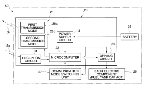
FIG 3 is a block diagram representing a control device of the motorcycle.
FIG 4 is a block diagram representing an electronic key in the first
embodiment.
FIG 5 is a timing chart representing authentication communication of the
control device of the first embodiment, a non-contact medium and a gas stand,
respectively.
FIG 6 is a block diagram of a control device according to a second embodiment
of the present invention.
FIG. 7 is a flowchart representing an authentication method according to the
second embodiment.
FIG 8 is a timing chart representing authentication communication of a
conventional control device, non-contact medium and gas stand, respectively.
DETAILED DESCRIPTION OF THE INVENTION
Hereinafter, the first embodiment of the present invention will be described
with
reference to drawings.
As shown in FIG 1, a smart key system 10 having a control device 20 mounted
in a motorcycle 50 (see FIG 2) and a portable electronic key (hereinafter,
referred to as
"electronic key") 30 which a user of the motorcycle 50 carries controls an
operation of
each of electric components 25 of the vehicle (vehicle-mounted device) on the
basis of
wireless communication between the control device 20 and the electronic key
30.
As shown in FIG 2, the motorcycle 50, which is a large two-wheeled vehicle of
a road sport type, is equipped with a cowl 51 which covers a body frame (not
shown); a
front fork 52 which is supported at a front end portion of the body frame in
order to
rotatably move; a front wheel 53 which is rotatably supported at the front
fork 52 by an
axle; a steering handle 54 connected to an upper end portion of the front fork
52; a front
CA 02690426 2010-01-18
9
cowl 55 which covers the steering handle 54 from the front face thereof; and a
screen 56
which stands backwards obliquely from the upper end portion of the front cowl
55.
Also, a headlight 57 and a pair of front turn signals 58 are provided in the
front side of
the front cowl 55 and a pair of rear view mirrors 59 are provided in the
lateral sides
thereof The above-described control device 20 is mounted inside this
motorcycle 50.
In addition, as described later, the motorcycle 50 shown in FIG 2 stops
between
neighboring gas stands (first gas stand 60 and second gas stand 61) in a gas
station.
The control device 20 of the motorcycle 50 includes a power supply circuit 21,
a
microcomputer 22, a reception circuit 23, a transmission circuit 28, a
communication
mode switching unit 27 and a driving circuit 24, as shown in FIG 3.
The power supply circuit 21 supplies a power supplied from a battery 26 to the
microcomputer 22, the reception circuit 23, the transmission circuit 28, the
communication mode switching unit 27, the driving circuit 24, and each of the
electric
components 25 and so on.
The reception circuit 23 has a reception antenna (not shown), receives a
command signal Sa transmitted from the electronic key 30 via this antenna,
takes it from
a carrier and then outputs a demodulated signal to the microcomputer 22. In
addition,
the command signal Sa output from the electronic key 30 includes data
indicating
operation patterns commanded by a user such as the opening of a fuel tank cap
and so on,
and ID data of the electronic key 30.
The microcomputer 22 receives the command signal Sa demodulated by the
reception circuit 23 and checks the ID data of the command signal Sa with ID
data stored
in a ROM (not shown). When the check for the ID data is right, the
microcomputer 22
outputs a signal (hereinafter, referred to as "ON signal") for operating the
driving circuit
24.
CA 02690426 2010-01-18
The driving circuit 24 becomes operable (hereinafter, referred to as "ON
state")
based on the ON signal from the microcomputer 22 and controls each of the
electric
components 25 mounted on the vehicle according to the operation pattern data
described
above. In detail, the driving circuit 24 permits the starting of an engine of
the
5 motorcycle 50 based on data indicating an operation pattern of the ON
signal and thus
enables it to be driven, or controls the opening of the fuel tank cap and the
like.
The transmission circuit 28 has a transmission antenna (not shown) and outputs
a request signal Sr modulated by a carrier via the transmission antenna in a
predetermined authentication range (for example, a radius of about 3m).
10 Here, the transmission circuit 28 has the first transmission mode 28a
and the
second transmission mode 28b which are different from each other in a
communication
start timing (authentication communication time and authentication
communication
interval) within one period.
In detail, as shown in FIG 5, authentication communication is performed twelve
times in one period (408 msec) in the first transmission mode 28a, and an
authentication
communication time of one time (the first authentication communication time)
is set to
34 msec. In other words, the request signal Sr is output throughout one period
in the
first transmission mode 28a.
On the other hand, in the second transmission mode 28b, authentication
communication is performed twelve times within one period (408 msec) in the
same
manner as the first transmission mode 28a, and an authentication communication
time of
one time (the second authentication communication time) is set to be shorter
than that in
the first transmission mode 28a. In detail, an authentication communication
time of one
time is set to 12.5 msec and there is an authentication communication interval
of 21.5
msec between the respective authentication communications.
CA 02690426 2010-01-18
11
In addition, the communication mode switching unit 27 switches communication
modes of the request signal Sr output to the electronic key 30 and can output
the request
signal Sr for authentication communication to the electronic key 30 by means
of any one
of the first transmission mode 28a and the second transmission mode 28b which
are
selected by a user.
The electronic key 30 is formed in a card shape and contains assembled IC
chips,
including a battery 31, a power supply circuit 32, an operation unit 33, a
transmission
circuit (communication unit) 34 and a reception circuit 38, as shown in FIG.
4.
The power supply circuit 32 is a circuit for supplying power from the battery
31
to the reception circuit 38, the transmission circuit 34 and the operation
unit 33.
The reception circuit 38 has a reception antenna (not shown), receives the
request signal Sr output from the above-described transmission antenna of the
control
device 20 via the reception antenna, and determines whether or not the
electronic key 30
is in an authentication range of the control device 20 by demodulating the
received
request signal Sr.
The operation unit 33 selects operation patterns for operating the respective
electric components 25 of the motorcycle 50. The user selects a desired
operation
pattern by use of the operation unit, and thereby a signal based on the
operation pattern is
output to the transmission circuit 34 together with ID data.
The transmission circuit 34 has a transmission antenna (not shown) and outputs
a command signal Sa, consisting of the operation pattern selected on the
operation unit
33 and the ID data and modulated by a carrier, to the above-described
reception circuit 23
of the control device 20.
To continue, an operation thereof will now be described. In this embodiment,
as shown in FIG 2, when the above-described motorcycle 50 is refueled with gas
CA 02690426 2010-01-18
12
between the neighboring gas stands (the first gas stand 60 and the second gas
stand 61) in
a gas station, a case of opening the fuel tank cap by operating an actuator of
the fuel tank
cap ("fuel tank cap ACT") among the respective electric components 25 of the
motorcycle 50 will be described.
At first, an authentication method of the smart key system 10 at the time of a
typical operation will be described. Further, a communication mode of the
transmission
circuit 28 of the control device 20 is initially set to the first transmission
mode 28a.
As shown in FIGS. 3 and 4, in order to authenticate the electronic key 30 and
the
control device 20, the user carries the electronic key 30 and enters the
authentication
range of the transmission antenna of the control device 20. In the state where
the
electronic key 30 enters the authentication range of the transmission antenna
of the
control device 20, the request signal Sr is output from the transmission
antenna of the
control device 20 by operating operation switches (not shown) provided in the
motorcycle 50. The reception antenna of the electronic key 30 receives the
request
signal Sr. Thereby, authentication communication of the electronic key 30 and
the
control device 20 is confirmed.
Next, the command signal Sa is demodulated and output from the transmission
circuit 34 of the electronic key 30 based on the received request signal Sr.
In addition, the control device 20 receives the output command signal Sa by
the
reception circuit 23, and then the reception circuit 23 takes the command
signal Sa from
the carrier. The reception circuit 23 demodulates the command signal Sa taken
from the
carrier and outputs it to the microcomputer 22. The microcomputer 22 having
received
the demodulated command signal Sa reads out the ID data of the motorcycle 50
from the
ROM and checks it with the ID data of the command signal Sa. When the ID data
of
the motorcycle 50 and the ID data of the command signal Sa are identical to
each other,
CA 02690426 2010-01-18
13
the microcomputer 22 completes the mutual authentication and outputs the ON
signal to
the driving circuit 24.
The driving circuit 24 having received the ON signal opens the fuel tank cap
by
driving the electric component (in this embodiment, the fuel tank cap ACT) 25
based on
the operation pattern.
As shown in FIG 2, however, when the authentication of the control device 20
of the motorcycle 50 and the electronic key 30 is performed in the vicinity of
the gas
stands 60 and 61 in the gas station, during the authentication of the gas
stands 60 and 61
and another non-contact medium (for example, during authentication of an ID
for
confirming permission to use the gas stands 60 and 61), the electronic key 30
is
sometimes not authenticated. In other words, when the external devices (the
gas stands
60, 61) using a frequency close to the frequency of the request signal Sr are
present
within the authentication range (for example, a radius of about 3m) of the
request signal
Sr of the control device 20, radio waves output from antennas (not shown) of
the gas
stands 60 and 61 interfere with a radio wave of the request signal Sr output
from the
control device 20. Thereby, there is a problem in that another non-contact
medium
creates a disturbance in the request signal Sr output from the transmission
circuit 28.
Here, as shown in FIG 5, the non-contact medium communicating with the gas
stands 60 and 61 performs authentication communication four times within one
period
(376 msec), and the first and second authentication communication times are 36
msec,
and the third and fourth authentication communication times are 76 msec.
Further,
interval durations having times different from each other are set between the
respective
authentication communication times, and an authentication communication
interval
between the first authentication communication and the second authentication
communication is set to 68 msec, and an authentication communication interval
between
CA 02690426 2010-01-18
14
the other authentication communications is set to 28 msec. That is to say, the
above-described period (408 msec) of the authentication communication of the
electronic
key 30 is set to be longer than the period (376 msec) of the authentication
communication of the non-contact medium.
Meanwhile, the first gas stand 60 of the gas stands 60 and 61 communicating
with the non-contact medium performs authentication communication four times
within
one period (376 msec) like the non-contact medium, the first authentication
communication time is 36 msec, the second and fourth authentication
communication
times are 12 msec, and the third authentication communication time is 76 msec.
Also,
interval durations having times different from each other are set between the
respective
authentication communications, an interval between the first and second
authentication
communications is set to 68 msec, an interval between the second and third
authentication communications is set to 52 msec, an interval between the third
and fourth
authentication communications is set to 28 msec, and an interval between the
fourth
authentication communication and the first authentication communication of the
next
period is set to 92 msec.
In addition, the second gas stand 61 performs authentication communication
four times within one period (376 msec) like the non-contact medium, the first
and third
authentication communication times are 12 msec, the second authentication
communication time is 36 msec, and the fourth authentication communication
time is 76
msec. Also, interval durations having times different from each other are set
between
the respective authentication communications, an interval between the first
and second
authentication communications is set to 92 msec, an interval between the
second and
third authentication communications is set to 28 msec, an interval between the
third and
fourth authentication communications is set to 92 msec, and an interval
between the
CA 02690426 2010-01-18
fourth authentication communication and the first authentication communication
of the
next period is set to 28 msec. The non-contact medium and the gas stands 60
and 61
perform the authentication communication during the duration (for example, the
duration
A in FIGS. 5 and 8) when the mutual authentication communication times
overlap.
5 In this case, as shown in FIG 8, if authentication of the smart key
system 10 is
to be performed during the authentication time period (for example, the
durations A and
B in FIG. 8) of the non-contact medium and the gas stands 60 and 61, there is
a problem,
as described above, in that the radio wave output from the non-contact medium
becomes
a disturbance on the request signal Sr output from the transmission circuit
28. For this
10 reason, in order to perform the authentication of the smart key system
10 without being
affected by the disturbance resulting from the non-contact medium, for
example, the
authentication of the electronic key 30 and the control device 20 is required
to be
performed during the interval duration (the duration C in FIG 8) of the
authentication
communications of the non-contact medium and the gas stands 60 and 61.
15 In this case, referring to FIG 5 again, the authentication
communication time in
the first transmission mode 28a in the control device 20 is set to 34 msec and
is set to be
longer than the other authentication communication intervals (28 msec) except
for the
authentication communication interval (68 msec) between the first
authentication
communication and the second authentication communication in the non-contact
medium.
In other words, the authentication communication time in the first
transmission mode 28a
is set to be shorter than the longest one of the authentication communication
intervals of
the authentication communication in the non-contact medium. Thereby, the
request
signal Sr output in the first transmission mode 28a can work only between the
first
authentication communication and the second authentication communication in
the
non-contact medium.
CA 02690426 2010-01-18
16
Therefore, in this embodiment, when the authentication of the control device
20
and the electronic key 30 is not performed even after the elapse of a
predetermined time,
that is, when the control device 20 does not react and the fuel tank cap is
not open
irrespective of the electronic key 30 being present in the authentication
range of the
control device 20, the user switches the first transmission mode 28a into the
second
transmission mode 28b by operating the communication mode switching unit 27.
Thereby, communication start timings of the authentication communication by
the
non-contact medium and the authentication communication by the control device
20
become different from each other. Further, the authentication communication
time in
the second transmission mode 28b is set to be shorter than that in the first
transmission
mode 28a and is also set to be shorter than the respective authentication
communication
intervals of the authentication communication in the non-contact medium.
Thereby, the
authentication communication by the second transmission mode 28b can be
performed
during the respective interval durations of the authentication communication
in the
non-contact medium, and thus authentication of the electronic key 30 is easily
performed
during the interval duration of the authentication communication in the non-
contact
medium compared with the authentication communication by the first
transmission mode
28a.
That is to say, when the authentication communication time of the request
signal
Sr is included in the interval duration of the authentication communication in
the
non-contact medium in the state where the electronic key 30 is in the
authentication
range of the control device 20 (when they completely overlap each other: for
example,
the duration D in FIG. 5), the reception circuit 38 of the electronic key 30
can receive the
request signal Sr.
The command signal Sa is output to the control device 20 from the transmission
CA 02690426 2010-01-18
17
circuit 34 in this state by operating the operation unit 33 of the electronic
key 30. This
allows the fuel tank cap to be opened according to the method described above.
As
above, the refueling can be smoothly carried out by working the fuel tank cap
ACT due
to the authentication communication between the control device 20 and the
electronic
key 30.
Therefore, in this embodiment, when the authentication of the control device
20
and the electronic key 30 is not performed in the first transmission mode 28a
for a
predetermined time, the communication start timings of the authentication
communication by the non-contact medium and the authentication communication
by the
electronic key 30 become different from each other due to being changed by the
communication mode switching unit 28 into the second transmission mode 28b
having
the authentication communication interval and the authentication communication
time
different from those of the first transmission mode 28a. In detail, the
authentication
communication time of the authentication communication in the second
transmission
mode 28b is set to be shorter than the respective authentication communication
intervals
of the authentication communication in another non-contact medium and thereby
the
authentication communication by the second transmission mode 28b can be
performed
during the respective interval durations of the authentication communication
in the
non-contact medium. For this reason, the authentication communication of the
electronic key 30 can be easily performed while the authentication
communication of
another non-contact medium is not performed. Thereby, it is possible to
decrease the
probability that the reception circuit 23 of the control device 20 will be
affected by
disturbance resulting from the non-contact medium even when there are external
devices
(gas stands 60 and 61) using a frequency close to the frequency of the request
signal Sr in
the vicinity of the motorcycle 50 in the gas station or the like. Accordingly,
the
CA 02690426 2010-01-18
18
authentication of the electronic key 30 can be promptly performed by the
control device
20, and there is no concern that a user will be displeased or incorrectly
assume there is a
defect in the electronic key 30, etc.
In addition, the communication start timings of the authentication
communication by another non-contact medium and the authentication
communication
by the control device 20 become different from each other at each period by
setting the
period (408 msec) of the authentication communication in the transmission
circuit 28
longer than the period (378 msec) of the authentication communication in
another
non-contact medium.
In other words, the communication start timings shift at each period as much
as
the difference between the two periods and this keeps outputting the request
signal Sr to
the electronic key 30 in the second transmission mode 28b, thereby increasing
the
probability of performing the authentication communication of the electronic
key 30
during the interval duration of the authentication communication of another
non-contact
medium. Therefore, the authentication of the electronic key 30 can be promptly
performed by decreasing the probability that the transmission circuit 28 will
be affected
by the disturbance resulting from the non-contact medium.
In addition, in this embodiment, the control device 20 side just includes the
communication mode switching unit 27 and the respective transmission modes 28a
and
28b in order to have a simple configuration, thus complicated circuit
configurations need
not be provided in both sides of the electronic key 30 and the motorcycle 50
as in the
conventional technique and an increase in the manufacturing cost can be
prevented.
Next, the second embodiment of the present invention will now be described
with reference to FIG. 6. The present embodiment refers as appropriate to FIG
3, and
the same elements as the first embodiment are rendered by the same reference
numerals
CA 02690426 2010-01-18
19
and description thereof will be omitted.
The communication mode of the transmission circuit 28 is manually switched by
the operation of a user in the above-described first embodiment; in contrast,
the smart
key system according to the second embodiment automatically switches the
communication mode when authentication is not performed despite outputting the
request signal Sr a predetermined number of times.
As shown in FIG 6, a communication mode switching unit 127 of a control
device 120 includes a determination unit 128 and a counter 129.
The counter 129 counts the number of output times of the request signal Sr
from
the transmission circuit 28 of the control device 120, in order to perform
authentication
communication of the electronic key 30 (refer to FIG 4) and the control device
120.
The determination unit 138 reads out the number of output times of the request
signal Sr
counted by the counter 139 and makes a determination so that a switching is
carried out
in the transmission circuit 28 when the number of output times exceeds a
threshold value.
In detail, as shown in the flowchart of FIG. 7, at first, the request signal
Sr is
output to the electronic key 30 in the first transmission mode 28a in step Sl.
Subsequently, in step S2, the electronic key 30 receives the request signal Sr
from the control device 120, and it is determined whether or not
authentication
communication with the electronic key 30 begins.
If the determination result in step S2 is "YES," the electronic key 30
receives
the request signal Sr from the control device 120, it is determined that the
authentication
communication of the control device 120 and the electronic key 30 begins, and
the
process goes to step S3.
In step S3, in the same manner as the above-described first embodiment, the
control device 120 receives, by the reception circuit 23, the command signal
Sa output
CA 02690426 2010-01-18
from the electronic key 30, demodulates the received the command signal Sa and
outputs
it to the microcomputer 22. The microcomputer 22 checks the ID data of the
motorcycle 50 and the ID data of the command signal Sa. When mutual
authentication
between the ID data of the motorcycle 50 and the ID data of the command signal
Sa is
5 completed, the driving circuit 24 is driven in order to open the fuel
tank cap (step S4).
On the other hand, if the determination result in step S2 is "No" (if the
authentication with the electronic key 30 is not performed despite outputting
the request
signal Sr a predetermined number of times), it is determined that there is
concern about
the interference of a radio wave output from antennas (not shown) of the gas
stands 60
10 and 61 with the request signal Sr output from the control device 120,
and then the
process goes to step S5.
Next, in step S5, it is determined whether or not the transmission mode is
switched, based on the number of output times of the request signal Sr counted
by the
counter 139. In detail, the determination unit 138 determines whether or not
the number
15 of output times of the request signal Sr counted by the counter 139
exceeds a threshold
value. If the determination result in step S5 is "NO" (if the value counted by
the
counter 139 is smaller than the threshold value), it is determined that more
time is needed
for communication, not that there is interference, and then the process
reiterates the flow
from step Si.
20 On the other hand, if the determination result in step S5 is "YES" (if
the value
counted by the counter 139 is equal to or more than the threshold value), it
is determined
that the radio wave from the gas stands 60 and 61 interferes with the request
signal Sr
from the control device 120, and then the process goes to step S6.
In step S6, the determination unit 138 enables the transmission circuit 28 to
carry out a switching operation. In detail, the communication mode switching
unit 127
CA 02690426 2010-01-18
21
outputs a switching signal to the transmission circuit 28 via the
microcomputer 22 and
the transmission circuit 28 switches the communication mode from the first
transmission
mode 28a to the second transmission mode 28b based on the switching signal, in
the
same manner as the first embodiment.
Thereafter, the control device 120 performs authentication with the electronic
key 30 by use of the second transmission mode 28b according to the flow
identical to the
above-described flow. That is, in this embodiment, the first transmission mode
28a and
the second transmission mode 28b are alternately switched by the communication
mode
switching unit 127 until the authentication is completed.
According to this embodiment, in addition to achieving the same effect as the
above-described first embodiment, it is possible to automatically determine
disturbance
resulting from other non-contact media without the switching operation of the
transmission circuit 28 by a user. Therefore, the operational complexity and
difficulty
in making a determination of disturbance can be solved in order to improve the
operability, a user is not displeased and the electronic key 30 can be
promptly
authenticated by the control device 120.
In addition, the communication mode switching unit 127 may determine
disturbance based on a period, as well as determine it based on the number of
output
times of the request signal Sr. Furthermore, the transmission circuit 28 may
be
configured to be switched at a time point when an output time of the request
signal Sr
exceeds a predetermined time.
While preferred embodiments of the invention have been described and
illustrated above, it should be understood that these are exemplary of the
invention and
are not to be considered as limiting. Additions, omissions, substitutions, and
other
modifications can be made without departing from the spirit or scope of the
present
CA 02690426 2010-01-18
22
invention. Accordingly, the invention is not to be considered as being limited
by the
foregoing description, and is only limited by the scope of the appended
claims.
For example, the cases of switching the two communication modes in the
transmission circuit have been described in the first and second embodiments;
however,
these are not limiting and a plurality of kinds of communication modes may be
employed.
Also, an authentication communication time and an authentication communication
interval may be appropriately adjusted.
Further, the case where the above-described motorcycle 50 stops between the
neighboring gas stands 60 and 61 in a gas station and is refueled with gas has
been
illustrated in these embodiments; however, this is not limiting and the
present invention
is also applicable under various circumstances where there are external
devices using
frequencies close to the frequency of the radio wave (request signal Sr) used
by the smart
key system 10.
Also, in these embodiments, the case where the transmission circuit 28 has the
two communication modes of the first transmission mode 28a and the second
transmission mode 28b has been illustrated; however, this is not limiting and
the
transmission circuit 28 may have two transmission circuits, for example, such
as a first
transmission circuit and a second transmission circuit, having different
communication
modes.
Further, the smart key system according to the present invention may be
mounted in a three-wheeled vehicle or a four-wheeled vehicle and is not
limited to the
two-wheeled vehicle.