Note: Descriptions are shown in the official language in which they were submitted.
CA 02690684 2013-11-26
DUMP TRAILER WITH ADJUSTABLE TIPPING HINGE
FIELD OF THE INVENTION
The present invention relates to a dump trailer having an adjustable
tipping hinge, and more particularly relates to dump trailer in which the
tipping hinge
has a first mounting position corresponding to a forward position of the tub
of the
trailer and a second mounting position corresponding to a rearward position of
the tub
of the trailer in which a rear end of the tub is farther rearward in the
rearward position
than in the forward position.
BACKGROUND
Dump trailers are commonly used in many different fields and
applications. A typical dump trailer comprises an elongate tub arranged to be
supported at a front end on a hitch of a towing vehicle, for example a fifth
wheel hitch,
and supported at a rear end on a rear wheel assembly. A tipping hinge assembly
couples the rear end of the tub to the frame supported on the rear wheel
assembly
while a suitable lifting mechanism is coupled between the front end of the tub
and the
frame supporting the hitching member thereon. In this manner, the front end
can be
elevated by pivoting the tub about the rear tipping axis of the tipping hinge
assembly
from a generally horizontal transport position to a downward and rearward
inclined
dumping position.
In most applications, it is desired to have the rear wheels close to the
rear end of the tub for optimal weight distribution of the material in the tub
between
the rear wheel assembly and the wheels of the towing vehicle upon which the
front
end of the tub is supported by the hitching member. This arrangement typically
results
in a minimal overhang of the rear end of the tub locating the end gate thereon
in
relation to the frame and rear wheel assembly upon which it is supported.
CA 02690684 2013-11-26
2
Alternatively, when using a dump trailer with paving equipment, it is
typically preferred to dump paving material directly from the dump trailer to
the inlet
hopper of paving equipment without spilling onto the surrounding area, which
typically
requires a larger overhang of the rear of the tub beyond the trailer frame and
rear
wheels.
The current method used by all manufacturers is to therefore require the
customer to specify which amount of overhang is desired so that the trailer
can be
manufactured, and purchased in that configuration. The trailer is now less
suitable for
other uses, prompting many customers to own more trailers simply so that there
are
trailers of both configurations available. The trailer is subsequently limited
to that
application so that a customer may potentially require purchasing more than
one
trailer where varied applications are desired.
US 6,880,894 by Obermeyer discloses a dump trailer for asphalt paving
including a hinge arm extending upward and forward from the tipping axis to
the rear
end of the trailer to encourage more rearward positioning of the tub in the
dumping
position. The forward inclination of the hinge arm requires that the rear end
of the tub
be displaced upwardly as well as rearwardly as it is pivoted from the
transport position
to the dumping position so that considerably more force is required for
lifting to a
dumping position. Also, the trailer in this instance cannot be reconfigured so
that the
trailer must generally be dedicated to a use for asphalt paving.
Canadian patent 1,265,549 by Hicks; and US patents 4,958,854 by
Parks; 4,948,155 by Smith et al.; and 3,181,914 by Humes disclose further
variations
to trailers in which the rear wheel assemblies can be adjusted relative to the
trailer
frame. While the adjustment of the rear wheels can optimize weight
distribution, no
means are disclosed for varying the amount of overhang of the tub relative to
the
CA 02690684 2013-11-26
3
wheels without varying the overall wheelbase of the rear wheels relative to
the towing
vehicle. Accordingly the applications of these trailers remain relatively
limited while
also requiring a considerably more complex mounting structure of the trailer
onto the
rear wheel assembly.
SUMMARY OF THE INVENTION
According to one aspect of the invention there is provided a dump trailer
for use with a towing vehicle, the trailer comprising:
a frame extending in a longitudinal direction between a front end and a
rear end;
a hitching member mounted on the front end of the frame so as to be
arranged to support the front end of the frame on the towing vehicle;
a rear wheel assembly mounted on the rear end of the frame so as to be
arranged to support the rear end of the frame for rolling movement along the
ground
in the longitudinal direction;
a tub arranged to be supported on the frame, the tub comprising a floor
and upright side walls extending in the longitudinal direction from a front
end including
a front wall spanning between the side walls to a rear end which is open so as
to be
arranged to dump material from the tub therethrough; and
a tipping hinge supporting the rear end of the tub on the rear end of the
frame such that the tub is pivotal relative to the frame about a tipping axis
between a
transport position in which the front end and the rear end of the tub are
supported
adjacent to the frame and a dumping position in which the tub is rotated about
the
tipping axis in relation to the transport position such that the front end of
the tub is
spaced upwardly from the frame in relation to the transport position;
the tipping hinge comprising a first portion arranged to be fixed relative
CA 02690684 2013-11-26
4
to a first mounting surface on the tub and a second portion arranged to be
fixed
relative to a second mounting surface on the frame, the first and second
portions
being coupled so as to be pivotal relative to one another about the tipping
axis;
at least one of the first and second portions being arranged to be
mounted in fixed relation to the respective mounting surface in either one of
a first
mounting position corresponding to a forward position of the tub supported on
the
frame and a second mounting position corresponding to a rearward position of
the tub
supported on the frame in which the tub is spaced farther rearward in relation
to the
frame in the rearward position than in the forward position while in the
transport
position of the tipping hinge.
In the illustrated embodiment, the tub is thus arranged to remain fixed in
a selected one of the forward position corresponding to the first mounting
position of
the tipping hinge or the rearward position corresponding to the second
mounting
position of the tipping hinge as the first and second portions of the tipping
hinge are
pivoted relative to one another between the dumping position and the transport
position.
The adjustable nature of the tipping hinge assembly allows the
repositioning of the tub, and accordingly the adjustment of the overhang of
the rear
end of the tub relative to the frame while the wheelbase remains fixed.
Accordingly a
single trailer can accommodate both optimal wheel loading as well as an
optimal
overhang of the rear end of the tub for specific applications such as asphalt
paving in
a manner which can be readily modified by an end user. Accordingly a
manufacturer
can manufacture a single trailer configuration at lower cost which can be
subsequently reconfigured by a dealer or end user as may be desired with
minimal
tooling requirements.
CA 02690684 2013-11-26
When the frame includes a cradle portion arranged to support the tub
directly thereon in the transport position, preferably the tub is spaced
farther rearward
in relation to the cradle of the frame in the rearward position than in the
forward
position.
5 The
tipping hinge preferably comprises a pair of tipping hinge
assemblies mounted laterally spaced apart from one another in a direction of
the
tipping axis.
The open end of the tub is preferably spaced farther rearward from the
tipping axis in the rearward position of the tub than the forward position of
the tub.
When a position of the first portion of the tipping hinge on the first
mounting surface differs between the forward position and the rearward
position of the
tub, the first portion of the tipping hinge is preferably arranged to be fixed
onto the first
mounting surface on the tub in either one of the first mounting position
corresponding
to the forward position of the tub or the second mounting position
corresponding to
the rearward position.
The first portion of the tipping hinge is preferably arranged to be fixed
relative to the tub by threaded fasteners in both the first and second
mounting
positions.
The first portion of the tipping hinge and the first mounting surface
preferably comprise uptight members such that the fasteners are arranged to
extend
generally horizontally through cooperating apertures in the first portion of
the tipping
hinge and the first mounting surface of the tub.
When the first mounting surface and the first portion of the tipping hinge
each comprise an upright flange, the upright flanges of the first mounting
surface and
the first portion are preferably mounted to one another in an overlapping
configuration
CA 02690684 2013-11-26
6
in both the first and second positions.
There may be provided a shoulder formed alongside one of the upright
flanges of the tipping hinge in which the shoulder is abutted against an end
of the
other one of the upright flanges in at least one of the first and second
positions
There may be provided a common lift cylinder mounted between the
front end of the frame and the front end of the tub in both the forward and
rearward
position of the tub.
In some embodiments, at least one of the first and second portions are
arranged to be mounted in relation to the respective mounting surface in any
one of a
plurality of intermediate mounting positions in which each intermediate
mounting
position corresponding to a respective position of the tub supported on the
frame
between the forward and rearward positions.
When the first portion of the tipping hinge comprises a mounting portion
arranged to be mounted on the first mounting surface of the tub and a pivot
portion
arranged to be pivotally coupled to the second portion, the mounting portion
may
comprise a plurality of mounting apertures arranged for connection by suitable
fasteners to co-operating mounting apertures in the first mounting surface of
the tub in
which the plurality of mounting apertures of the mounting portion correspond
to
different mounting positions of the tub relative to the frame.
The first portion of the tipping hinge preferably comprises a mounting
portion arranged to be mounted on the first mounting surface of the tub and a
pivot
portion arranged to be pivotally coupled to the second portion. In a preferred
embodiment, the pivot portion is identical in orientation in both the forward
position
and the rearward position.
Alternatively, according to a further embodiment, the mounting portion
CA 02690684 2013-11-26
7
may be reversibly mounted on the first mounting surface in the second position
in
relation to the first position. In this instance, the pivot portion of the
first portion of the
tipping hinge may be offset from a center of the mounting portion in the
longitudinal
direction when a position of the mounting portion of the first portion of the
tipping
hinge in relation to the tub in the longitudinal direction is substantially
identical in both
the first and second positions.
In some embodiments, one of either the first mounting surface or the
first portion of the tipping hinge comprises a plurality of projections and
the other one
of the first mounting surface and the first portion comprises a plurality of
recesses
arranged to mate with the projections therein in both the first and second
positions.
In this instance, one of the projections and the recesses may comprise a
first set and a second set in which the first set is mated with the other one
of the
projections and the recesses in the first position and the second set is mated
with the
other one of the projections and the recesses in the second position. The
projections
and the recesses are preferably arranged to be slidably displaced relative to
one
another in a substantially vertical direction between an engaged position in
the first
and second positions and a released position in which the first portion is
separated
from the first mounting surface.
Some embodiments of the invention will now be described in
conjunction with the accompanying drawings in which:
BRIEF DESCRIPTION OF THE DRAWINGS
Figure 1 is a perspective view of a preferred embodiment of the dump
trailer including an adjustable tipping hinge according to the present
invention.
Figure 2 is a perspective view of the trailer of Figure 1 illustrating a
bottom and rear side of the trailer.
CA 02690684 2013-11-26
8
Figure 3 is a side elevational view of the tub and a rear portion of the
frame of the trailer of Figure 1 shown connected by the tipping hinge shown in
broken
line in a first mounting position and shown in solid line in a second mounting
position
in which the tub is forward of the first mounting position.
Figure 4 and Figure 5 are side elevational views of the tipping hinge
according to a second embodiment in a first mounting position corresponding to
a
forward position of the tub and a second mounting position corresponding to a
second
position of the tub respectively in the transport position.
Figure 6 and Figure 7 are rear bottom perspective views of the tipping
hinge of Figures 4 and 5 in the first mounting position and the second
mounting
position respectively.
Figure 8 is a perspective inner side view of one of the tipping hinge of
Figures 4 and 5 in the forward transport position.
Figure 9 is a perspective outer side view of the tipping hinge according
to Figure 8.
Figure 10 is a side elevational view of the dump trailer including the
tipping hinge according to the preferred embodiment of Figure 1.
Figure 11 is a perspective view of the tipping hinge according to the
preferred embodiment of Figure 1.
Figure 12 and Figure 13 are side elevational views of the preferred
embodiment of the tipping hinge in the transport position and the dumping
position
respectively in which the hinge is in the first mounting position.
Figure 14 and Figure 15 are side elevational views of the preferred
embodiment of the tub in the second mounting position of the tub as the tub is
pivoted
between the transport position and dumping position respectively.
CA 02690684 2013-11-26
9
In the drawings like characters of reference indicate corresponding parts
in the different figures.
DETAILED DESCRIPTION
Referring to the accompanying Figures there is illustrated an adjustable
tipping hinge which is particularly suited for use with a dump trailer 12 in
which the
tipping hinge comprises two tipping hinge assemblies 10 which are supported
laterally
spaced apart from one another adjacent a rear end of the trailer.
The dump trailer with which the tipping hinge is used typically comprises
a main frame 14 extending in a longitudinal direction from a front end 16 to a
rear end
18. The main frame 14 primarily comprises two elongate beams spanning the full
length of the main frame between the front end and rear end thereof so as to
extend
in the longitudinal direction parallel and spaced apart from one another. A
plurality of
cross bars 22 span laterally between the two elongate beams 20 at
longitudinally
spaced positions to support the beams in fixed relation to one another.
A hitching member 24 is mounted between the beams adjacent the front
end 16 thereof so as to be arranged to support the front end of the trailer on
a fifth
wheel hitch of a highway truck tractor for towing in which the hitching member
24
couples to the fifth wheel hitch plate for relative pivotal movement about a
vertical
hitch axis.
The frame is supported for rolling movement on the ground in the
longitudinal direction by a rear wheel assembly 26 which supports the rear end
of the
frame thereon. In the illustrated embodiment the rear wheel assembly comprises
set
of three axles 28 which are parallel and spaced apart from one another in the
longitudinal direction to support the beams thereon by suitable suspension
members
coupled between the axles and the main frame. The rear wheel assembly is
generally
CA 02690684 2013-11-26
fixed in the longitudinal direction relative to the main frame including the
hitching
member thereof.
The trailer further comprises a tub 32 supported on the main frame and
comprising a floor 34 and two side walls 36 mounted in a generally U-shaped
5
configuration with the floor to extend together with the floor in the
longitudinal direction
between the front end rear ends of the tub. A front wall 38 encloses the front
end of
the tub while the rear end of the tub is open between the side walls for
dumping the
material of the tub therethrough. The tub may additionally expand from front
to back
as a result of a tapered profile of the floor and/or wall panels.
10 An end
gate is arranged to be supported on the rear end of the tub
which typically comprises a gate panel hinged at a top end to the tub for
pivotal
movement about a horizontal gate axis between a closed position spanning the
open
end of the tub and an open position in which the bottom end of the gate panel
is
pivoted outwardly away from the tub for dumping.
The two tipping hinge assemblies 10 are spaced apart in the lateral
direction of the tipping axis for commonly pivotally coupling the rear end of
the tub to
the rear end of the main frame. The tipping axis is generally horizontal and
perpendicular to the longitudinal direction and is arranged to be
substantially fixed in
location in relation to the main frame in the illustrated embodiment. The tub
is pivotal
relative to the main frame between a transport position and a dumping
position. In the
transport position the tub extends generally horizontally forward from the
rear end at
the pivot axis such that the front end of the tub is supported on the front
end of the
frame. A cradle 40 is provided on the top side of the main frame to extend
rearward
from the front end thereof to support the front end of the floor of the tub
directly
thereon in the transport position. The cradle 40 remains fixed in relation to
the main
CA 02690684 2013-11-26
11
frame.
In the dumping position, the front end of the tub is displaced upwardly so
as to be spaced above the frame and spaced above the location of the front end
of
the tub in the transport position. Furthermore in the dumping position, the
tub is
pivoted about the pivot axis at the rear of the main frame and tub so that the
tub
extends upwardly and forwardly from the pivot axis.
The tub is arranged to be displaced from the transport position to the
dumping position by a lift mechanism 42 coupled between the front end of the
main
frame and the front end of the tub. In the illustrated embodiment the lift
mechanism
comprises a hydraulic piston cylinder having a cylinder end coupled to the
front end of
the tub and a piston end coupled to the front end of the frame such that
extension of
the hydraulic piston cylinder causes the front end of the tub to be raised
from the
frame while contracting the hydraulic piston cylinder returns the front end of
the tub to
the transport position.
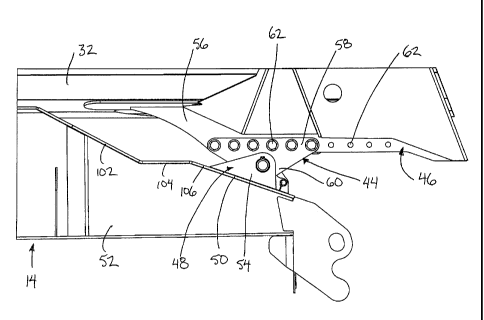
Each tipping hinge assembly comprises a first portion 44 arranged to be
fixedly mounted to a first mounting surface 46 of the tub and a second portion
48
arranged to be fixedly mounted to a second mounting surface 50 of the main
frame.
Each beam of the main frame is arranged to support a respective one of
the tipping hinge assemblies at a rear portion 52 thereof. The rear portion 52
of each
beam is located above the rearmost axle and comprises an end portion of the
beam
where a top side of the beam is sloped downwardly and rearwardly to the rear
end of
the beam to define the second mounting surface 50 on the main frame.
In Figures 4 through 9, the second portion 50 of each tipping hinge
assembly comprises two parallel mounting plates 54 which are parallel and
laterally
spaced apart from one another in fixed welded connection to the top side of
the rear
CA 02690684 2013-11-26
12
portion of the beam defining the second mounting surface such that the plates
are
generally vertical and parallel to the longitudinal direction of the trailer.
The two
mounting plates 54 are each generally triangular in shape having a base side
fixed to
the second mounting surface 50 of the main frame and an opposing apex locating
a
pivot mounting location of the hinge axis. The two mounting plates 54 of each
second
portion are arranged to receive the corresponding first portion 44 pivotally
therebetween for connection by a horizontal pivot pin extending commonly
through
the first and second portions at the location of the hinge axis.
The tub 32 includes two frame members 56 fixed onto the bottom side of
the floor of the tub adjacent the rear end thereof in which the two frame
members
extend in the longitudinal direction of the trailer parallel and are spaced
apart from
one another for alignment with respective ones of the beams of the main frame.
The
frame members 56 comprise upright flanges which depend downwardly from the
bottom side of the floor of the tub to define the first mounting surfaces 46
of the tub.
The first portions 44 in this instance also comprise upright flanges in the
form of triangular plates having a base side defining a mounting portion 58
along the
top edge of the flange and a pivot portion 60 comprising a lower apex of the
triangular
plate opposite the mounting portion 58. The pivot portion 60 locates a pivot
pin
mounting location adjacent the apex thereof for alignment with the pivot pin
mounting
locations of the two mounting plates of the second portion 48 between which
the
triangular plate of the first portion 44 is received. The pivot portion 60 is
offset from a
centre of the mounting portion in the longitudinal direction so as to be
located
adjacent and directly below one of the two longitudinally opposed ends of the
mounting portion 58 of the first portion.
A plurality of cooperating apertures 62 are provided in both the upright
CA 02690684 2013-11-26
13
flanges of the first portion 44 and first mounting surface 46 of each tipping
hinge
assembly so as to be spaced apart from one another in a longitudinally
extending row.
The cooperating apertures in the two upright flanges of each tipping hinge
assembly
are arranged to align with one another to receive threaded fasteners
therethrough for
selectively fixing the first portion to the first mounting surface when the
upright flanges
are mounted in an overlapping configuration parallel and alongside one
another. The
first portions of the tipping hinge assembly are spaced apart farther than the
upright
flanges defining the first mounting surfaces of the tub such that each first
portion
overlaps an outer side of the respective flange against which it is mounted
and
fastened by horizontally extending bolts extending through the cooperating
apertures
62 therebetween.
The first portions of the two tipping hinge assemblies are each arranged
to be mounted onto the respective first mounting surfaces in both a first
mounting
position corresponding to a forward position of the tub supported on the frame
and a
second mounting position corresponding to a rearward position of the tub
supported
on the frame. The first mounting position is illustrated in Figures 4 and 6
and the
second mounting position is in Figures 5 and 7.
In the first position of the first portions fixed to the first mounting
surfaces of the tub, the forward position of the tub results in a small
overhang of the
tub designated by X in Figure 4. In this instance the pivot portion 60 is
positioned at
the rear end of the first portion with the mounting portion extending forward
therefrom
so that the corresponding mounting location of the first portion on the first
mounting
surface of the tub is generally forward of the tipping axis.
In the second position, the first portion is mounted on substantially the
identical location in the longitudinal direction on the first mounting surface
of the tub
CA 02690684 2013-11-26
14
as compared to the first position; however, the forward and rearward ends of
the
mounting portion are reversed in relation to one another as compared to the
first
position by flipping about a vertical axis between the first and second
positions.
Accordingly in the second position the pivot portion of the portion is located
at a
forward end and the mounting portion extends substantially rearward therefrom
along
with the mounting location of the first portion on the tub so that the tub is
spaced
rearward in the rearward position as compared to the forward position as
measured in
the longitudinal direction.
The hinge axis remains fixed in relation to the frame and the other fixed
components of the frame including the cradle, the rear wheel assembly and the
hitching member so that displacement of the tub between the forward and
rearward
positions relative to the frame also displaces the tub in relation to the
cradle, the rear
wheels and the hitching member. By relocating the tub rearward relative to the
hinge
axis in the rearward position as compared to the forward position, the tub is
accordingly positioned farther rearward in the longitudinal direction in
either one of the
transport or dumping positions when in the rearward position of the tub and
the
second position of the first portion.
In the rearward position of the tub, the resulting overhang exceeds the
overhang designated by X in Figure 4 by an additional amount designated by Y
in
Figure 5 which may be in the order of one foot in dimension for example. When
dumping in the rearward position, the inclination of the tub in the dumping
position is
substantially identical in either mounting positions of the first portion so
as to extend
generally downward and rearward to the open rear end; however, in the rearward
position the rear end extends farther rearward and downward in relation to the
forward
position. The greater overhang permits a greater reach into the inlet hopper
of paving
CA 02690684 2013-11-26
equipment for example.
The upright flange of each first portion 44 also comprises a supporting
portion 64 along both sides of the flange in which the two supporting portions
64
include a top edge which defines a shoulder 66 extending generally in the
longitudinal
5
direction substantially parallel to the top edge of the upright flange but
spaced
therebelow. In this manner each of the shoulders 66 is suitably positioned for
abutment with the bottom edge of the upright flange defining the first
mounting
surface 46 of the tub when mounted in an overlapping configuration with the
upright
flange of the first portion.
10 Each
shoulder on the opposing sides of the upright flange of the first
portion is arranged to only abut the bottom edge of the upright plate forming
the first
mounting surface in a respective one of either the first or second positions
of the
tipping hinge assembly. As the first mounting surfaces of the tub are
positioned
inwardly in relation to the first portions which overlap the outer sides
thereof, it is
15
accordingly only the shoulder 66 located along the inner side of the upright
flanges of
the first portions which is used in either one of the first or second
positions. By
reversing the flanges forming the first portions between the first and second
mounting
positions thereof different ones of the shoulders 66 will accordingly be
positioned
along the inner side for abutment against the bottom edge of the first
mounting
surface.
The bottom edge of each of the upright flanges of the tub defining the
first mounting surfaces is arranged to be oriented in the longitudinal
direction of the
tub so as to extend generally horizontally in the transport position. Each
bottom edge
includes a plurality of recesses 68 formed therein in a row in the
longitudinal direction
of the tub so as to define corresponding projections 70 extending generally
CA 02690684 2013-11-26
16
downwardly between adjacent ones of the recesses 68.
Each shoulder 66 of the supporting portions of the first portion includes
a corresponding mating top edge having a plurality of upward projections 72
which
extend upwardly to respective pointed apexes spaced apart in the longitudinal
direction in a row. The projections 72 accordingly define respective recessed
74
between adjacent one of the projections. In this manner the mating profiles of
the
shoulders 66 and the bottom edges of the first mounting surfaces can be mated
with
one another by relative sliding movement in a generally vertical direction
between an
engaged position of the projections 70 into the recesses 74 and the
projections 72
into the recesses 68 in either one of the forward or rearward positions and a
disengaged position of the recesses and projections by separating the first
portions
from the first mounting surfaces during reconfiguration of the trailer.
By providing two shoulders 66 along opposing sides of each first portion,
each first portion includes a first set of projections and recesses
therebetween along
one side which only mates in the first position of the tipping hinge assembly
corresponding to the forward position of the tub while the projections and
recesses
therebetween along the other shoulder form a second set only arranged to mate
with
the first mounting surface in the second position of the tipping hinge
assemblies
corresponding to the rearward position of the tub. Typically one threaded
fastener is
provided in association with each of the projections in the first mounting
surface of the
tub flanges for alignment with corresponding apertures in the upright flange
of the first
portion so that the threaded fasteners received through the cooperating
apertures
between the first portions and the first mounting surfaces function primarily
to
maintain the recesses and projections in an engaged position relative to one
another
during pivotal movement of the tub between transport and dumping position in
either
CA 02690684 2013-11-26
17
one of the forward configuration or rearward configurations of the tub.
Referring now to the preferred embodiment of Figures 1 through 3 and
Figures 10 through 15, many features are substantially identical to the
previous
embodiment in which like parts are referred to using the same reference
numerals.
In the preferred embodiment, the frame 14 of the dump trailer 12 again
comprises a pair of beams 20 joined by crossbars 22. The beams 20 span in a
longitudinal direction between a front end supporting the hitching member 24
thereon
and a rear end supported on a similar configuration of the rear wheel assembly
26.
The construction of the tub 32 is also substantially identical so as to
comprise a floor,
upright side walls 36, and a front wall 38. The lift mechanism 42 permits the
tub to be
pivoted on laterally spaced tipping hinge assemblies 10 between the transport
position supported in a generally horizontal orientation on the cradle 40 of
the frame
and a dumping position extending downward at a rearward incline to dump the
contents of the tub through the open rear end of the tub.
The two frame members 56 along the bottom side of the tub at the rear
portion thereof in the preferred embodiment again comprise upright mounting
plates
joined to the tub by horizontal mounting flanges at the top edge of the plate.
The
bottom edge in this instance is substantially straight in the longitudinal
direction of the
tub from a front end to a rear end. The front end is sloped upwardly and
forwardly so
as to join the tub floor similarly to the profile of the rear portions 52 of
the beams. The
rear end is abutted with the rear end wall of the tub which surrounds the gate
assembly. An opening 100 is provided extending laterally through each frame
member 56 adjacent the rear end thereof for receiving various conduits and the
like
therethrough. Similarly to the previous embodiment the two frame members 56
define
the first mounting surface 46 onto which the respective tipping hinge
assemblies 10
CA 02690684 2013-11-26
18
are mounted onto the tub.
In the preferred embodiment, the rear portions 52 of the two beams of
the frame are substantially stepped in profile comprising a first portion 102
extending
downwardly and rearwardly from the top side of the beam for alignment with the
front
edge of the respective frame member 56. A second portion 104 extends
horizontally
rearward from the bottom end of the first portion 102 spaced below the top end
of the
beam by a distance corresponding approximately to the height of the upright
plates
forming the frame members 56.
The horizontal second portion 104 thus extends alongside and bellow
the bottom edge of the respective frame member 56 in the forward position of
the tub
when pivoted into the transport position as shown in Figure 14. A third
portion 106
extends downwardly and rearwardly from the rear end of the second portion 104
to
the rear end of the rear portion 52 and defines the mounting surface 50 on the
frame
which supports the second portion 48 of the hinge thereon as in the previous
embodiment. The second portion 48 of the hinge in this instance is similarly
formed of
two triangular plates mounted parallel and spaced apart from one another in an
upright orientation in fixed and welded relation to the second mounting
surface 50 of
the frame.
The first portion 44 of each hinge 10 is received between the two plates
forming the second portion 48. The first portion 44 also comprises a generally
triangular plate defining a pivot portion 60 at a lowermost apex which
receives the
hinge pin of the hinge therethrough for connection to the two plates of the
second
portion 48. Also like the previous embodiment, the first portion 44 extends
upward
from the apex to an opposing flat side of the plate defining the mounting
portion 58
which is selectively mounted to the first mounting surface 46 on the tub.
CA 02690684 2013-11-26
19
Each of the mounting portions 58 and the first mounting surface 46
comprise a row of cooperating apertures formed therein which is aligned in the
longitudinal direction of the tub in the mounted position. Both the mounting
portion 58
and the first mounting surface 46 again comprise upright mounting plates which
are
mounted in an overlapping configuration such that the first mounting surface
46
defined by each frame member overlaps an inner side of the respective mounting
portion 58 of the two first portions 44 of the two hinge assemblies 10. A
plurality of the
cooperating apertures 62 in the mounting portions 58 and the first mounting
surface
46 are aligned with one another in each of the forward and rearward positions
of the
tub relative to the frame to receive threaded fasteners therethrough in a
horizontal
orientation for fastening in a secure and readily releasable manner.
In the first mounting position of Figures 14 and 15, the tub is positioned
in the forward position relative to the frame so that all of the apertures 62
in the
mounting portion 58 are aligned with respective ones of the apertures in the
frame
members which correspond to the rearmost apertures therein. The front end of
the
frame members are thus positioned in close proximity to the respective first
portions
102 of the rear portions 52 of the beams of the frame. This corresponds to a
first
prescribed overhang of the tub relative to the frame through pivotal movement
of the
tub between the transport and dumping positions.
When it is desired to increase the rearward projecting overhang of the
tub relative to the frame, the tub is displaced into the rearward position
thereof by
displacing the mounting of the first portion of the hinge relative to the
frame members
on the tub into the second mounting position shown in Figures 12 and 13. In
this
instance the tub is slidably displaced reward in the longitudinal direction
thereof
relative to the hinge assembly components fixed on the frame so that each of
the
CA 02690684 2013-11-26
apertures in the mounting portions 58 of the hinge assemblies are instead
aligned
with forwardmost ones of the apertures 62 in the row of apertures in the frame
members 56 of the tub. The tub in this instance when positioned in the
rearward
position is again spaced further rearward relative to the frame, the cradle on
the
5 frame, the rear wheel assembly, and the hitching member of the frame
similarly to the
previous embodiment.
In both the first and second mounting positions some of the apertures in
the frame member 56 are mounted to respective ones of the apertures in the
mounting portion 58; however, they are aligned with different ones of the
apertures
10 depending on the position of the tub. Each mounting position of the tub
thus
corresponds to a unique combination of apertures 62 in the mounting portions
58 and
the frame members 56 which are aligned with one another and which receive
fasteners therethroug h.
Also similarly to the previous embodiment, each of the plates forming
15 the first portions 44 of the hinge assemblies further comprise an
additional plate along
an inner surface thereof. The additional plate on the inner surface defines a
supporting portion 64 having a top edge parallel and spaced below the top edge
defining the mounting portion 58 to define a shoulder 66 along an inner side
of each
first portion 44. The shoulder 66 extends in the longitudinal direction of the
tub and is
20 positioned so as to be aligned in engagement with the bottom edge of the
respective
frame member 56 in either of the mounted positions of the tub. The supporting
portions 64 provide support for the tub on the hinge assemblies to increase
the
structural support of the fasteners while also providing a suitable surface
along which
the frame members 56 are slidable when the fasteners are released for
displacement
of the tub between the forward and rearward positions.
CA 02690684 2013-11-26
21
Due to the plurality of apertures located at intermediate positions
between the first and second mounting positions of the hinge assembly
corresponding
to the forward and rearward positions of the tub relative to the frame, in the
preferred
embodiment the tub can also be mounted at a plurality of intermediate
positions
relative to the frame between the forward and rearward positions. In each
intermediate mounting position of the mounting portion 58 to the respective
frame
members 56, a unique combination of apertures of the frame member are aligned
with
the apertures in the mounting portion which corresponds to a unique prescribed
amount of rearward projecting overhang of the tub relative to the frame which
is in
between the prescribed overhang amounts of the forward and rearward positions
respectively. In either of the mounting positions of the hinge assembly and
the
corresponding positions of the tub relative to the frame in the longitudinal
direction,
the connection of the first portion and second portion of the hinge assemblies
remains
identical so that the position of the first portions of the hinge assemblies
relative to the
frame remain substantially identical in any one of the forward, intermediate
or reward
positions of the tub relative to the frame. In each instance the position of
the tub
relative to the first and second portions of the hinge assemblies are varied
with
variation of the longitudinal position of the tub relative to the frame.
To retain the hinge pins more securely, in the preferred embodiment a
retainer plate 108 is mounted about the inner end of each hinge pin of the two
hinge
assemblies. The retainer plates 108 are each secured to the innermost one of
the two
plates defining the second portion of the hinge by a suitable fastener
connected to the
retainer plate at a position spaced radially from the tipping axis of the
hinge pin.
In either embodiment, the lift mechanism 42 comprises a hydraulic
piston cylinder configuration in which the lift cylinder is the same one which
remains
CA 02690684 2013-11-26
22
mounted between the frame and the tub regardless of the position of the tub
relative
to the frame between the forward and rearward positions thereof. The mounting
location, length and configuration of the lift cylinder are arranged in each
instance so
that the tub is moveable through a full range of tipping motion between the
transport
position and the dumping position regardless of the position of the tub
relative to the
frame between the forward and rearward positions thereof. In the illustrated
embodiment, the base of the lift cylinder is mounted centrally on the frame in
the
lateral direction at a longitudinal position immediately forward of the front
wall of the
tub in the transport position. The front wall extends upwardly at a forward
inclination to
a top end which mounts the top end of the lift cylinder laterally centered
thereon such
that extension of the lift cylinder causes the front end of the tub to be
lifted relative to
the frame into the dumping position as in the previous embodiment.