Note: Descriptions are shown in the official language in which they were submitted.
CA 02690792 2014-03-12
SMART PANEL
Background
1. Field of the Invention
[0001] The invention is directed to flooring and, in particularly, panels
and
systems for vented flooring.
2. Background of the Invention
[0002] Conventional flooring uses a plurality of layers composed of
different
types of materials. The materials and the design of the structure support the
weight of the
floor itself and objects intended to be placed on or supported by the floor.
Such flooring
is sometimes designed such that a minimal amount of space exists between the
various
layers and material components to provide increased strength.
[0003] A problem with these flooring systems is that they do not provide
aeration
and are susceptible to undesirable environmental conditions. For example, in a
gymnasium or other athletic arena, the flooring system is subjected to high
humidity, slab
migration and water leaks caused by clogged plumbing, roof leaks, or burst
pipes in the
walls or flooring, all of which can damage the flooring materials as well as
the flooring
system. Although a small amount of water may seem fairly innocuous, even small
amounts of water and water vapor that persists in the floor can lead to
rotting, mold, and
the generation of distasteful odors. Larger amounts of water and high humidity
cause
structural and aesthetic damage to the flooring system as well as the
surrounding area.
Damage to these areas is difficult or impossible to detect, absent actual
removal of the
floor itself, and can result in unwanted expansion of the floor components
(buckling),
excessive contraction producing voids, deterioration, drastic shortening of
the life of the
component materials, and an often unexpected inability of the flooring to
sustain any
significant weight, resulting in, at best, structural damage, and personal
injury.
Structurally damaged areas are nearly always difficult and expensive to
replace, often
requiring installation of an entirely new flooring system. Additionally, slow
migration of
water into a flooring system may continue, undetected, until it causes
significant damage.
1
CA 02690792 2014-03-12
[0004] Moreover, damp flooring also attracts insects such as termites and
other
creatures. These creatures often nest in damp areas of the flooring or
subflooring, which
becomes a long term habitat attracting and resulting in the proliferation of
even more
creatures.
[0005] U.S. Patent No. 6,101,775 to Mark Larimore discloses a system of
aerated
flooring. It is further desirable to have a flooring panel and system that
allows for sub-
floor ventilation and moisture monitoring.
Summary of the Invention
[0006] The present invention overcomes the problems and disadvantages
associated with current strategies and designs and provides devices and
systems for
ventilating flooring.
[0007] One embodiment of the invention is directed toward a sub-floor
panel.
The panel is comprised of a base, at least one support structure coupled to
the base, and
at least one ventilation channel adjacent to the support structure.
[0008] In the preferred embodiment, the base and the support structure are
a
single unit. Preferably, the sub-floor panel is prefabricated. In the
preferred
embodiment, the support structure is a support strip running at least one of
the length of
the panel, the width of the panel, and at a 45 degree angle of the panel and
the ventilation
channels are parallel to the support structures.
[0009] The support structure is preferably adapted to be coupled to a
finished
floor and the base is preferably adapted to be coupled to a sub-floor. The
panel
preferably has a moisture sensor positioned within the at least one
ventilation channel.
More preferably, each ventilation channel has at least one moisture sensor. In
the
preferred embodiment, each ventilation channel is created by removing material
from the
base.
2
CA 02690792 2010-01-22
[0010] Another embodiment of the invention is directed toward a second sub-
floor panel. The panel includes a body having an upper surface and a lower
surface, at
least one indentation in the upper surface adapted to allow air flow across at
least a
portion of the upper surface, and at least one support structure between the
upper surface
and the lower surface.
[0011] In the preferred embodiment, the sub-floor panel is prefabricated.
The
support structure is preferably a support strip running at least one of the
length of the
panel, the width of the panel, and at a 45 degree angle of the panel and the
indentations
are parallel to the support structures. Preferably the support structures are
adapted to be
coupled to a finished floor and the body is adapted to be coupled to a sub-
floor.
[0012] The panel preferably also includes at least one moisture sensor
positioned
within the at least one indentation. More preferably, each indentation has at
least one
moisture sensor. Preferably the indentations are created by removing material
from the
body.
[0013] Another embodiment of the invention is directed to a flooring
system.
The system includes a finished floor, a plurality of sub-floor panels coupled
to the
finished floor, and a sub-floor coupled to the sub-floor panels. Each sub-
floor panel
comprises a base, at least one support structure coupled to the base, and at
least one
ventilation channel adjacent to the at least one support structure.
[0014] In the preferred embodiment, the system also includes an air
circulating
device that forces air through the ventilation channels of the sub-floor
panels. The air
circulating device can be permanent or removable. Preferably there is at least
one
moisture sensor positioned within the at least one ventilation channel. More
preferably,
each ventilation channel has at least one moisture sensor.
[0015] In the preferred embodiment, the moisture sensors and the air
circulating
device are in communication. Preferably, the air circulating device is adapted
to turn on
upon detection of moisture by the moisture sensor and turn off upon detection,
by the
moisture sensor, of moisture levels below a predetermined threshold level.
[0016] The flooring system can also include at least one shock absorbing
device
positioned between the plurality of sub-floor panels and the sub-floor and at
least one
riser positioned between the plurality of sub-floor panels and the sub-floor.
Preferably,
3
CA 02690792 2010-01-22
the risers provide additional ventilation channels below the sub-floor panel.
In the
preferred embodiment, the base and support structures are a single unit.
Preferably, the
sub-floor panel is prefabricated.
[0017] Preferably, at least one support structure is a support strip
running at least
one of the length of the panel, the width of the panel, and at a 45 degree
angle of the
panel and preferably the ventilation channels are parallel to the support
structures.
Preferably, the ventilation channels are created by removing material from the
base.
[0018] Another embodiment of the invention is directed to a second flooring
system. The flooring system includes a finished floor, a plurality of sub-
floor panels
coupled to the finished floor, and a sub-floor coupled to the lower surface of
the sub-floor
panels. Each sub-floor panel comprises a body having an upper surface and a
lower
surface, at least one indentation in the upper surface adapted to allow air
flow across at
least a portion of the upper surface, and at least one support structure
between the upper
surface and the lower surface.
[0019] In the preferred embodiment, the system also includes an air
circulating
device that forces air through the indentations of the sub-floor panels. The
air circulating
device can be permanent or removable. Preferably, the system also includes at
least one
moisture sensor positioned within the at least one indentation. More
preferably, each
indentation has at least one moisture sensor. The moisture sensors and the air
circulating
device are preferably in communication. In the preferred embodiment, the air
circulating
device is adapted to turn on upon detection of moisture by the moisture sensor
and turn
off upon detection, by the moisture sensor, of moisture levels below a
predetermined
threshold level.
[0020] The system can include at least one shock absorbing device
positioned
between the plurality of sub-floor panels and the sub-floor and at least one
riser
positioned between the plurality of sub-floor panels and the sub-floor.
Preferably, the
risers provide additional ventilation channels below the sub-floor panel.
[0021] In the preferred embodiment, the sub-floor panel is prefabricated.
Preferably, the support structure is a support strip running at least one of
the length of the
panel, the width of the panel, and at a 45 degree angle of the panel and the
indentations
4
CA 02690792 2014-03-12
are parallel to the support structures. Preferably, the indentations are
created by
removing material from the body.
[0021a] In accordance with another aspect of the invention, there is
provided a
sub-floor panel comprising: a solid base having a flat first surface; a
plurality of support
structures extending perpendicularly from a second surface of the base, the
second
surface parallel to the first surface; a plurality of ventilation channels,
each ventilation
channel disposed between at least two support structures; at least one
moisture sensor
positioned within a ventilation channel; and a ventilation system adapted to
circulate air
within at least one ventilation channel; wherein the base and the support
structures are a
single unit and both first surface of the base and the plurality of support
structures are
adapted to abut a finished floor.
[0021b] In accordance with another aspect of the invention, there is provided
a
sub-floor panel wherein the support structures are couplable to the finished
floor and the
base is couplable to a sub-floor.
[0021c] In accordance with another aspect of the invention, there is provided
a
sub-floor panel further comprising at least one moisture sensor positioned
within each
ventilation channel.
[0021d] In accordance with another aspect of the invention, there is provided
a
sub-floor panel wherein the plurality of ventilation channels are disposed
between the
base and the finished floor.
[0021e] In accordance with another aspect of the invention, there is provided
a
flooring system comprising: a finished floor; a plurality of sub-floor panels
coupled to the
finished floor, wherein each sub-floor panel comprises a solid base having a
flat first
surface; a plurality of support structures extending perpendicularly from a
second surface
of the base, the second surface parallel to the first surface; a plurality of
ventilation
channels, each ventilation channel disposed between at least two support
structures; at
least one moisture sensor positioned within a ventilation channel; and an air
circulating
device adapted to circulate air within the sub-floor panels; and a sub-floor
coupled to the
sub-floor panels; wherein the base and the support structures are a single
unit and the
finished floor overlaps at least one seam between the plurality of sub-floor
panels.
4a
CA 02690792 2014-03-12
[0021f] In accordance with another aspect of the invention, there is
provided a
flooring system wherein each ventilation channel has at least one moisture
sensor.
[0021g] In accordance with another aspect of the invention, there is provided
a
flooring system wherein each ventilation channel is disposed between the
finished floor
and the base.
4b
CA 02690792 2014-03-12
[0022] Other embodiments and advantages of the invention are set forth in
part in
the description, which follows, and in part, may be obvious from this
description, or may
be learned from the practice of the invention.
Description of the Drawings
[0023] The invention is described in greater detail by way of example only
and
with reference to the attached drawings, in which:
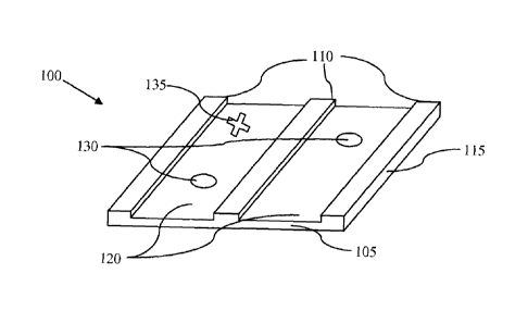
[0024] Figure 1 is an isometric view of an embodiment of a panel of the
invention.
[0025] Figure 2 is an isometric view of another embodiment of a panel of
the
invention.
[0026] Figure 3 is an isometric view of an embodiment of the system of the
invention.
Description of the Invention
[0027] As embodied and broadly described herein, the disclosures herein
provide
detailed embodiments of the invention. However, the disclosed embodiments are
merely
exemplary of the invention that may be embodied in various and alternative
forms.
Therefore, there is no intent that specific structural and functional details
should be
limiting, but rather the intention is that they provide a basis for the claims
and as a
representative basis for teaching one skilled in the art to variously employ
the present
invention.
[0028] A problem in the art capable of being solved by the embodiments of
the
invention is detection and removal of moisture below the finish floor of a
flooring
system. It has been surprisingly discovered that installing a panel having
ventilation
channels under the finish floor of a flooring system can assist in removing
moisture from
the system.
[0029] Figure 1 depicts an isometric view of one embodiment of a panel 100
of
the invention. Panel 100 may be used in all facets of the building and/or
construction
CA 02690792 2010-01-22
industry for example: residential, commercial, sports complexes, industry,
etc. Such uses
may include: roofing construction, flooring construction, interior or exterior
wall
construction, roofing deck construction, ceiling construction, or any other
type of
construction where any amount of ventilation of air and/or moisture would be
desirable.
Furthermore, panel 100 can be used in applications requiring insulation, for
example with
sprayed insulation, batts, loose blown insulation, etc. Additionally, panel
100 can be
used to facilitate wiring of the structure by providing conduits for the wires
to pass
through.
[0030] Panel 100 is preferably made of plywood; however other materials
can be
used. For example, panel 100 can be made of other woods, metal, plastic,
rubber, and/or
other man made or naturally occurring materials. While panel 100 is shown as a
square,
panel 100 can be another size or shape as dictated by the area into which
panel 100 is to
be installed. For example, panel 100 can be 24 inches wide by 96 inches long,
48 inches
wide by 60 inches long, combinations thereof, or other width and lengths.
Preferably,
panel 100 is manufactured offsite in easily transportable sizes and shipped to
the site
where they are to be used. However, panel 100 can be made onsite. In the
preferred
embodiment, multiple panels 100 are installed in a flooring system. However in
some
embodiments, only one panel 100 is used.
[0031] In the preferred embodiment, panel 100 has a base 105. Base 105
preferably extends over the entirety of panel 100. Base 105 preferably makes
up the
lower surface of panel 100; however base 105 can be the upper surface of panel
100.
Extending from base 105 are supports 110. In an preferred embodiment, supports
110 are
strips running the length or width of panel 100, depending on the location
into which
panel 100 is to be installed. However, in other embodiments, supports 110 can
be
attachment structures, for example nailing strips. Additionally supports 110
can be at
any angle to panel 100. Supports 110 can be of any height above base 105. For
example
supports 110 can be 0.25 inches tall, 0.5 inches tall or another height.
Furthermore,
supports 110 can be of any width. For example supports 110 can be 1 inch wide,
2 inches
wide, or another width. Furthermore, supports 110 need not be of equal widths.
While
three supports 410 are shown, one or more supports can be used. While supports
110 are
6
CA 02690792 2014-03-12
shown as equally spaced, the spacing can differ depending on the conditions of
the area
into which panels 100 are to be installed.
[0032] Supports 110 and base 105 make up the body 115 of panel 100. Body
115
can be of any height, for example body 115 can be 0.5 inches tall, 0.75
inches, tall or one
inch tall. In the preferred embodiment, body 115 is one unit. Body 115 can be
constructed, for example, by milling out ventilation channels 120 from body
115,
molding, or other methods of creating body 115 as one unit. In other
embodiments, body
115 can be manufactured by coupling supports 110 to base 105, for example by
adhesive,
screws, bolts, clips, welding, or other methods.
[0033] In the preferred embodiment the body 115 of panel 100 has
ventilation
channels 120. Preferably, ventilation channels 120 run parallel to supports
110.
Ventilation channels 120 are a width through which air can flow, for example 6
inches, 8
inches, or 12 inches. Furthermore, ventilation channels 120 need not be all of
equal
width or of equal spacing. While two ventilation channels 120 are shown, any
number of
ventilation channels can be used. Preferably, ventilation channels 120 are
uninterrupted
through the length or width of panels 100, depending on orientation.
Ventilation channels
120 are preferably rectangular in cross-section; however other cross-sectional
shapes can
be implemented, including but not limited to triangular shapes, trapezoidal
shapes, and
semicircular shapes.
[0034] With panel 100 having one or more channels, the air and/or moisture
will
be able to move and/or dissipate naturally or via mechanically forced methods,
for
example by using a blowing device, through the channel or multiple channels as
deemed
necessary. Thereby, helping to eliminate any moisture from reaching any sub-
floor
material and/or the finish material or any combination thereof. Thus, helping
to reach
and/or maintain a desired moisture content in the surrounding air space,
finish product
material, sub-base material, base material and/or any combination thereof.
Thus, greatly
reducing the potential of immediate or any future failure of the desired use
of a product as
it pertains to its functionality, expected useful life, etc. and/or any
combination thereof.
[0035] In a preferred embodiment, a moisture sensor is coupled to panel
100.
Preferably there is one moisture sensor 130 located within each ventilation
channel 120.
The moisture sensor can be an impedance moisture sensor, a chilled mirror
moisture
7
CA 02690792 2014-03-12
sensor, a hydrocarbon dew point moisture sensor or other sensor capable of
detecting
moisture. The moisture sensor can have an internal source of power (i.e. a
battery) or can
be connected to the structure's power system (i.e. via an electric plug). In
the preferred
embodiment, the moisture sensor triggers an alarm upon detection of moisture;
however
in other embodiments the moisture sensor can trigger a ventilation system 135
upon
detection of moisture. The moisture sensor can communicate via wired or
wireless
communication channels.
[0036] Figure 2 depicts an isometric view of a second embodiment of the
panel
200 of the invention. Panel 200 is similar to panel 100 except supports 210
are
protrusions from base 205 instead of strips. While supports 210 are show in
offset rows,
they can be in parallel rows, random arrangements, or other configurations.
Furthermore,
while supports 210 are shown as rectangular, they can be other shapes, for
example
circular, triangular, and square. The configuration of the supports of panel
200 allows for
ventilation from different angles, thus allowing for the ventilation device to
be placed at
different locations depending on the area where the panels 200 are installed.
[0037] Figure 3 depicts an isometric view of a portion of a flooring
system 300
using a panel 305 of the invention. Flooring system 300 includes a finished
floor 310.
Finished floor 310 can be any type of floor, including but not limited to real
or imitation
wood flooring, plywood flooring, carpeted flooring, metal flooring, marble
flooring, tile
flooring, and linoleum flooring. While the preferred embodiment is a flooring
system,
the system can be used in other building surfaces where moisture is
undesirable, for
example sheet rock, roofing, and/or sub-base material (i.e. sub-flooring,
studded walls,
and roof decking).
[0038] Finished floor 310 is coupled to one or more panels 305. Panel 305
is
preferably a panel as described herein. Finished floor 310 can be coupled to
panel 305 by
one or more methods including, but not limited to loose laid, adhesive,
screws, nails,
bolts, clips, and rivets. In the preferred embodiment, finished floor 310 is
coupled to the
supports of panel 305; however, finished floor 310 can be coupled to the base
of panel
305. While system 300 is shown with one panel 305 two or more panels 305 can
be
layered on top of each other.
8
CA 02690792 2010-01-22
[0039] Coupled to the underside of panel 305 can be at least one riser 315.
Risers
315 can be made of any material, can have any size, and can have any shape.
Risers 315
are used to adjust the height of finished floor 310 off of sub-floor 320. In
the preferred
embodiment, risers 315 are strips of wood that provide additional ventilation
space below
panels 305. Risers 315 are coupled to panel 305 and sub-floor 320 by one or
more
methods, including, but not limited to, loose laid, adhesive, screws, nails,
bolts, clips, and
rivets.
[0040] In some embodiments, for example athletic floors, flooring system
300
also includes at least one shock absorber 325. Preferably shock absorbers 325
are
positioned between panels 305 or risers 315 and sub-floor 320. In the
preferred
embodiment, shock absorbers 325 are made of rubber; however other materials
capable
of absorbing shocks can be used. Shock absorbers 325 are coupled to panel 305
or risers
315 and sub-floor 320 by one or more methods, including, but not limited to,
loose laid,
adhesive, screws, nails, bolts, clips, and rivets.
[0041] Flooring system 300 preferably has at least one moisture sensor, as
described herein. In the preferred embodiment, each ventilation channel has at
least one
moisture sensor. The moisture sensor can be affixed to a surface of the
ventilation
channel, the bottom surface of finished floor 310, or can be embedded into one
of the
surfaces. Preferably, the moisture sensors are in communication with a
ventilation
system. The ventilation system can be, for example, a fan or blower, an HVAC
system, a
heating or cooling unit, a controllable vent, or combinations thereof.
Furthermore, the
ventilation system can be permanent, removable, and/or repositionable.
[0042] In the preferred embodiment, the moisture sensor and the ventilation
system work together to detect and rid the flooring system 100 of moisture.
For example,
upon the moisture sensor detecting moisture, the moisture sensor can alert the
ventilation
system to activate and, once the moisture sensor detects that the moisture
level has
dipped below a predetermined threshold level, the moisture sensor can alert
the
ventilation system to deactivate. For a second example, since moisture may not
occur in
the vicinity of the moisture detector, the ventilation system can turn itself
on periodically
and circulate the air within the flooring system 300. The circulated air may
pick up
moisture and blow across the moisture sensor, thus causing the moisture sensor
to detect
9
CA 02690792 2014-03-12
that there is moisture within the flooring system 300 and indicate that the
ventilation
system should remain activated.
[0043] Other embodiments and uses of the invention will be apparent to
those
skilled in the art from consideration of the specification and practice of the
invention
disclosed herein. While particular embodiments of the present invention have
been
illustrated and described, it would be obvious to those skilled in the art
that various other
changes and modifications can be made. The scope of the claims should not be
limited
by the preferred embodiments set forth in the examples, but should be given
the broadest
interpretation consistent with the specification as a whole. Furthermore, the
term
"comprising of' includes the terms "consisting of' and "consisting essentially
of."