Note: Descriptions are shown in the official language in which they were submitted.
CA 02691064 2009-12-08
WO 2009/002827
PCT/US2008/067630
HELICAL AND SEGMENTED STENT-GRAFT
BACKGROUND
10001] Intraluminal prostheses used to maintain, open, or dilate blood
vessels are
commonly known as stents. Stent constructions generally include lattice type
cylindrical frames
that define a plurality of openings. Common frameworks for stews include, for
example,
individual rings linked along the length of the stent by a linking member, a
continuous helically
wrapped member (that may include one or more linking members), a braid or a
mesh formed into
a tubular structure, and a series of interconnected struts. Stents may be
formed by arranging one
or more members in a pattern along a longitudinal axis to define essentially a
cylinder and
connecting the one or more members or otherwise affixing them in position
(e.g., interconnecting
with a filament). Stents may also be formed by cutting openings into a tube of
material (e.g.,
shape memory).
[0002] Stents may have self-expanding and/or balloon expandable properties.
Self-
expanding stents are delivered to a blood vessel in a collapsed condition and
expand in vivo
following the removal of a constraining force and/or in the presence of an
elevated temperature
(due to material properties thereof), whereas balloon expandable stents are
generally crimped
onto a balloon catheter for delivery and require the outwardly directed force
of a balloon for
expansion. Stents can be made of various metals and polymers and can include a
combination of
self-expanding and balloon expandable properties.
100031 Synthetic vascular grafts are routinely used to restore the blood
flow in patients
suffering from vascular diseases. For example, prosthetic grafts made from
expanded
polytetrafluoroethylene (ePTFE) are commonly used and have shown favorable
patency rates,
meaning that depending on a given time period, the graft maintains an open
lumen for the flow
of blood therethrough. Grafts formed of ePTFE include a microstructure
characterized by spaced
apart nodes connected by fibrils, the distance between the nodes defined as
intemodal distance
(IND), and are generally extruded either as a tube or as a sheet or film that
is fashioned into a
tube. Grafts can also be created from fibers woven or knitted into a generally
tubular shape.
CA 02691064 2009-12-08
WO 2009/002827
PCT/US2008/067630
[0004] It is known in the art to use stents in combination with vascular
grafts to form
stent-grafts. Because stent-grafts are often intraluminally deployed in
vessels of varying sizes
and tortuosity, flexibility can be an important consideration. flexibility can
be imparted to a
stent-graft in a variety of ways, including, for example, connection of the
stent to the one or more
graft layers, configuration of the stent and/or graft layer(s), spacing of the
stent struts, rings, or
members along the length of the graft(s), etc. For example, U.S. Patent No.
6,398,803 and U.S.
Patent No. 6,770,087 to Layne et al. describe a graft layer with openings to
enhance flexibility.
Another important consideration in the design of a stent-graft is the ability
of the stent to
withstand stress and fatigue, caused, for example, by plastic deformations
occurring at strut
junctions when the stent is subjected to circumferential forces. Stent
strength can be enhanced
through material choice, stent configuration, arrangement and configuration of
graft layers,
connecting members between stent members, etc. Another consideration in the
design of certain
stent-grafts is properties to resist ItinIcing of the stent-graft. For
example, when a stent-graft is
positioned in a bend in a blood vessel or bypass graft, depending on the
acuteness of the angle of
the bend, the stent-graft can potentially kink and thereby become unsuitable
for passage of blood
therethrough.
100051 One example of an allegedly flexible and kink resistant stent-graft
is described in
U.S. Patent No. 6,042,605 to Martin et al., the stent-graft formed by
helically arranging an
undulating stent member about a graft member, interweaving a linking member
between
undulations in adjacent turns of the helical member, and helically arranging a
coupling member
in the form of a flat ribbon or tape around the assembly. Another example is
provided in U.S.
Patent No. 6,312,458 to Golds, the stent-graft formed from an elongate wire
helically wound
about a graft member at a first angle and an elongate securement member
helically wound over
both the stent and graft members at a second angle not congruent to the first
angle. Such a stent-
graft is alleged to be an improvement over the Martin et al. stent-graft both
because the use of a
broad coupling member is said to decrease the overall flexibility of the stent-
graft and because
wrapping the coupling member at the same angular orientation of the stent is
said to decrease
flexibility and expandability of the stent In each of these examples, however,
the outermost
layer is a thin tape, ribbon, thread or suture, rather than a support member,
such that the radial
strength of the stent-graft is limited.
2
CA 02691064 2014-11-26
(00061 The following references relate to stent-grafts: U.S. Patent No.
5,667,523 to
Bynon et al.; U.S. Patent No. 6,042,605 to Martin et al.; U.S. Patent No.
6,264,684 to Banas at
al.; U.S. Patent No. 6,312,458 to Golds; U.S. Patent No. 6,361,637 to Martin
et al., U.S. Patent
No, 6,398,803 to Layne at al.; U.S. Patent No. 6,520,986 to Martin at al.,
U.S. Patent No.
6,652,570 to Smith etal.; U.S. Patent No. 6,673,103 to Golds at al.; U.S.
Patent No. 6,770,087 to
Layne at al.; U.S. Patent No. 6,881,221 to Golds; U.S. Patent No. 6,911,040 to
Johnson at al.;
and U.S. Patent No. 6,945,991 to Brodeur at al.
[00071 Applicants have recognized that it would be desirable to provide a
stent-graft that
is able to combine flexibility, kink-resistance and good radial strength,
embodiments of which
are described herein along with methods of making same.
BRIEF SUMMARY
100081 Accordingly, a strong, flexible stent-graft is described herein.
In one
embodiment, an implantable prosthesis includes a generally tubular substrate,
a helix disposed
about an outer surface of the substrate along a longitudinal axis, the helix
having a first
thickness, a covering disposed over at least a portion of the helix, and a
support member coupled
to an outer surface of the covering, the support member having a second
thickness greater than
the first thickness.
[00091 in another embodiment, a stent-graft includes a helix disposed about
a substrate,
the helix having a first thickness, a covering disposed over at least a
portion of the helix, and a
support member coupled to the covering, the support member having a second
thickness greater
than the first thickness. In another embodiment, a stent-graft includes a
helix disposed about a
substrate, the material of the helix having a first stiffness, a covering
disposed over at least a
portion of the helix, and a support member coupled to the covering, the
support member material
having a second stiffness greater than the first stiffness.
[0010] In yet another embodiment, a stent-graft includes a helix disposed
about a
substrate, a covering disposed over at least a portion of the helix, and two
or more expandable
segments coupled to the covering, adjacent expandable segments spaced at least
about 3 mm
from each other. In still another embodiment, a stent-graft includes a self-
expanding helix
3
CA 02691064 2009-12-08
WO 2009/002827
PCT/US2008/067630
disposed about an ePTFE substrate, a covering disposed over at least a portion
of the helix, and a
plurality of spaced apart expandable segments coupled to the covering.
[0011] In one embodiment, a method of making a stent-graft includes winding
an
elongate member, having a first thickness, about a generally tubular substrate
to form a helix,
disposing a covering over at least a portion of the helix, bonding the
covering to at least one of
the substrate and helix, and coupling a support member, having a second
thickness greater than
the first thickness, to the covering.
[0012] These and other embodiments, features and advantages will become
more
apparent to those skilled in the art when taken with reference to the
following more detailed
description in conjunction with the accompanying drawings that are first
briefly described.
BRIEF DESCRIPTION OF THE DRAWINGS
[0013] FIG. 1 is a partial side view of a helix disposed about a substrate.
[0014] FIG. 2 is a partial side view of covering disposed over a portion of
the helix and
substrate of FIG. 1.
[0015] FIG. 3 is a partial side view of one embodiment of a stent-graft,
including a
support member coupled to an outer surface of the covering of FIG. 2.
[0016] FIG. 4 is another embodiment of a stent-graft, the covering
including an elongate
strip helically disposed about a helix and substrate.
[0017] FIG. 5 is another embodiment of a stent-graft, the covering
including spaced apart
rings disposed about a helix and substrate.
DESCRIPTION OF THE PREFERRED EMBODIMENTS
[0018] The following description should be read with reference to the
drawings, in which
like elements in different drawings are identically numbered. The drawings,
which are not
necessarily to scale, depict selected embodiments and are not intended to
limit the scope of the
invention. The description illustrates by way of example, not by way of
limitation, the principles
of the invention. This description will clearly enable one skilled in the art
to make and use the
4
CA 02691064 2009-12-08
WO 2009/002827
PCT/US2008/067630
invention, and describes several embodiments, adaptations, variations,
alternatives and uses of
the invention, including what is presently believed to be the best mode of
carrying out the
invention.
[0019] As used herein, the terms "about" or "approximately" for any
numerical values or
ranges indicate a suitable dimensional tolerance that allows the part or
collection of components
to function for its intended purpose as described herein. Also, as used
herein, the terms
"patient", "host" and "subject" refer to any human or animal subject and are
not intended to limit
the systems or methods to human use, although use of the subject invention in
a human patient
represents a preferred embodiment. In addition, the term "thickness" used with
respect to a
structural feature (e.g., helix, support member, stent, etc.) indicates a
distance from a first side of
the structure to a second side of the structure, where the first side may be
adjacent and/or coupled
to an underlying member (e.g., a substrate, covering graft, layer, etc.), and
where the second side
may be adjacent and/or coupled to an overlying member (e.g., a covering,
graft, layer, etc.).
[00201 The implantable prosthesis (e.g., stent-graft) described herein
includes a substrate
that forms a smooth inner luminal surface for the prosthesis, a helix disposed
about the substrate,
a covering disposed over at least a portion of the helix, and a support member
coupled to the
covering. The combination of a helix and support member (e.g., with spaced
apart expandable
segments) overcomes issues that are prevalent in certain stent-grafts lacking
such a combination.
For example, segmented stent-grafts (e.g., stent-grafts having a structure of
disconnected
expandable segments) are known to suffer from subduction, a condition known by
those skilled
in the art as a "Z-kink" because the stent-graft forms a "Z" shape when
adjacent segments
become offset from one another with respect to the longitudinal axis of the
stent-graft. Stent-
grafts including a graft material with a relatively thin wall are also known
to suffer from
billowing of the graft material into the inside surface or the lumen of the
stent-graft when
deployed. Billowing may occur when the stent-graft is positioned in an
undersized vessel (e.g.,
artery) and is characterized by substantially non-uniform radial expansion of
the stent-graft.
Utilizing a helix mitigates subduction and billowing issues and also imparts
excellent flexibility,
fatigue life and kink-resistance to the stent-graft. However, the helix alone
without a support
member suffers from a lack of radial strength. Thus, the stent-graft described
herein, including
CA 02691064 2014-11-26
both a helix and support member, enjoys a combination of advantageous features
that are
beneficial to the life and effectiveness of the stent-graft.
[0021) In one
embodiment, the substrate has a thickness generally in the range of
approximately 10 microns to approximately 200 microns, and preferably in the
range of
approximately 20 microns to approximately 80 microns. The substrate is
generally flexible and
compressible. Potential
materials for the substrate include, for example, expanded
polytetrafluoroethylene (ePTFE), polyester, Polyurethane,
fluoropolyraers,
polytetrafluoroethylene, silicones, urethanes, ultra high molecular weight
polyethylene, ararnid
fibers, and combinations thereof. One preferred embodiment for a substrate
material is ePTFE.
The node-fibril microstructure of an ePTFE substrate may include various
orientations for the
fibrils, but in a preferred embodiment, the fibrils are oriented generally
parallel to the
longitudinal axis of the substrate. The average internodal distance (IND) for
one preferred
embodiment of a substrate and/or covering described herein is in the range of
approximately 6
microns to approximately 80 microns. Also, as described in USPN 5,790,880 to
Banta et al.,
he substrate and/or covering may be made of an ePTFE that undergoes nodal
elongation
during radial expansion. An ePTFE substrate may be manufactured in a number of
ways,
including, for example, extrusion of a tube (seamless), extrusion of a sheet
that is
subsequently formed into a tube (one or more seams), helical wrapping of ePTFE
tape
around a mandrel (e.g., multiple seams or preferably a single helical seam),
etc.
[0022j The stent-
graft described herein may be utilized with bio-active agents. Bio-
active agents can be coated onto a portion or the entirety of the stent-graft,
substrate, and/or
covering for controlled release of the agents once the prosthesis is
implanted. The bio-active
agents can include, but are not limited to, vasodilator, anti-coagulants, such
as, for exarnple,
warfarin and heparin. Other bio-active agents can also include, but are not
limited to agents such
as, for example, anti-proliferativetantimitotic agents including natural
products such as vines
alkaloids (i.e. vinblastine, vineristine, and vinorelbine), paclitaxel,
epiciipodophyllotoxins (i.e.
etoposide, teniposide), antibiotics (dactinomyein (actinomycin D)
daunorubicin, doxorubicin and
idarubicin), anthracyclines, mitoxantrone, bleomycins, plicamycin (mithr-
arnycin) and
mitomycin, enzymes (L-asparaginase which systemically metabolizes L-asparagine
and deprives
6
CA 02691064 2009-12-08
WO 2009/002827
PCT/US2008/067630
cells which do not have the capacity to synthesize their own asparagine);
antiplatelet agents such
as G(GP)
inhibitors and vitronectin receptor antagonists; anti-
proliferativeiantimitotic
alkylating agents such as nitrogen mustards (mechlorethamine, cyclophosphamide
and analogs,
melphalan, chlorambucil), ethylenimines and methylmelamines
(hexamethylmelamine and
thiotepa), alkyl sulfonates-busulfan, nirtosoureas (carmustine (BCNU) and
analogs,
streptozocin), trazenes dacarbazinine (DTIC); anti-proliferative/antimitotic
antimetabolites such
as folic acid analogs (methotrexate), pyrimidine analogs (fluorouracil,
floxuridine, and
cytarabine), putine analogs and related inhibitors (mercaptopurine,
thioguanine, pentostatin and
2-chlorodeoxyadenosine {cladribine}); platinum coordination complexes
(cisplatin, carboplatin),
procarbazine, hydroxyurea, rnitotane, aminoglutethimide; hormones (i.e.
estrogen); anti-
coagulants (heparin, synthetic heparin salts and other inhibitors of
thrombin); fibrinolytic agents
(such as tissue plasminogen activator, streptokinase and urokinase), aspirin,
dipyridamole,
ticlopidine, clopidogrel, abciximab; antimigratory; antisecretory (breveldin);
anti-inflammatory;
such as adrenocortical steroids (cortisol, cortisone, fludrocoltisone,
prednisone, prednisolone,
6a-methylprednisolone, triamcinolone, betamethasone, and dexamethasone), non-
steroidal
agents (salicylic acid derivatives i.e. aspirin; para-aminophenol derivatives
i.e. acetominophen;
indole and indene acetic acids (indomethacin, sulindac, and etodalac),
heteroaryl acetic acids
(tolmetin, diclofenac, and ketorolac), arylpropionic acids (ibuprofen and
derivatives), anthranilic
acids (mefenamic acid, and meclofenamic add), enofic acids (piroxicam,
tenoxicam,
phenylbutazone, and oxyphenthatrazone), nabumetone, gold compounds (auranofm,
aurothioglucose, gold sodium thiomalate); immunosuppressives: (cyclosporine,
tacrolimus (FK-
506), sirolimus (rapamycin), azathioprine, mycophenolate mofetil); angiogenic
agents: vascular
endothelial growth factor (VEGF), fibroblast growth factor (FGF); angiotensin
receptor blockers;
nitric oxide donors; anti-sense oligionucleotides and combinations thereof;
cell cycle inhibitors,
mTOR inhibitors, and growth factor receptor signal transduction kinase
inhibitors; retenoids;
cyclin/CDK inhibitors; HMG co-enzyme reductase inhibitors (statins); and
protease inhibitors.
100231 The
helix and/or support member in one embodiment may be formed of a shape
memory material, including, for example, shape memory metals, shape memory
alloys, super
elastic shape memory metal alloys, linear elastic shape memory alloy, metal
alloys, shape
memory polymers, polymers, bio-resorbable material, and combinations thereof.
One preferred
shape memory material is Nitinol, while another is a cobalt chrome alloy. The
helix and/or
7
CA 02691064 2014-11-26
support member may also be formed of metal, such as, for example, stainless
steel, platimun, and
Elgiloy, or certain polymers. Moreover, portions of the helix and/or support
member may be
made of a bio-resorbable material. As used herein, the term "bio-resorbable"
includes a suitable
bio-compatible material, mixture of materials or partial components of
materials being degraded
into other generally non-toxic materials by an agent present in biological
tissue (i.e., being bio-
degradable via a suitable mechanism, such as, for example, hydrolysis) or
being removed by
cellular activity (i.e., bioresorption, bioabsorption, or bioresorbable}, by
bulk or surface
degradation (i.e., bioerosion such as, for example, by utilizing a water
insoluble polymer that is
soluble in water upon contact with biological tissue or fluid), or a
combination of one or more of
the bio-degradable, bio-erodable, or bio-resorbable material noted above.
Potential materials for
the prosthesis described herein include, for example, biodegradable polymers
such as polylactic
acid, i.e., PLA, polyglycolic acid, i.e., PGA, polydioxanone, i.e., PDS,
polyhydroxybutyrate, i.e.,
PHB, polyhydroxyvalerate, i.e., PHV and copolymers or a combination of PHB and
PHV
(available commercially as Biopolt), polycaprolactone (available as
Capronort),
polyanhydrides (aliphatic polyanhydrides in the back bone or side chains or
aromatic
polyanhydrides with benzene in the side chain), polyorthoesters,
polyaminoacids (e.g., poly-L-
lysine, polyglutamic acid), pseudo-polyaminoacids (e.g., with back bone of
polyaminoacids
altered), polycyanocrylates, or polyphosphazenes.
[0024] The helix may
be connected to the substrate by various methods, which can be
facilitated by the material selection for the helix, substrate and/or
coatings, if utilized. An
adhesive, a polymer bonded by a solvent, sutures, or other methods may be used
to connect the
helix to the substrate. Other alternatives known in the art are additionally
within the scope of the
invention, including weaving the substrate around the helix. The substrate may
additionally be
longitudinally compressed before connecting the helix thereto. The substrate
is compressed from a
first length to a second length, which is approximately 50% to about 97% of
the first length.
Longitudinal compression of an ePTFE graft is described in U.S. Patent No.
4,955,899 to Della
Coma et al. In one embodiment, an adhesive may be disposed between the helix
and the substrate
to bond the helix to the substrate. Suitable biocompatible bonding agents may
include
polytetrafluoroethylene, polyurethane, polyethylene, polypropylene,
polyamides, polyimides,
polyesters, polypropylenes, polyethylenes, polyfluoroethylenes, silicone
fluorinated polyolefins,
fluorinated
8
CA 02691064 2009-12-08
WO 2009/002827
PCT/US2008/067630
ethylene/propylene copolymer, perfluoroalkoxy fluorocarbon,
ethylene/tetrafiuoroethylene
copolymer, and polyvinylpyrolidone. The bonding agent may constitute an
interfacial layer
between the helix and the substrate, or may be a polymeric cladding at least
partially
concentrically surrounding the helix.
[0025] In another embodiment, a polymer may be applied to the helix, and a
solvent
applied over the helix to bond the helix to the substrate. A suitable solvent
may be an aprotic
solvent including dimethylacetamide (DMSE), dimethylforamide, THF, or their
mixtures. For
example, in one embodiment a generally tubular ePTFE substrate is positioned
over a mandrel.
The substrate may be sintered, unsintered, or partially sintered. The helix
with a polyurethane
coating over at least a portion of its length is positioned along the outer
surface of the ePTFE
substrate. Once the helix is initially positioned on a surface of the
substrate, a laser alignment
fixture is optionally utilized to optimally space the adjacent windings of the
helix with respect to
one another. The mandrel is then removed from the assembly and a solvent, such
as
tetrahydrofuran (THF), is applied to the inside surface of the ePTFE
substrate, so that the THF
migrates through the wall of the ePTFE substrate. The interaction between the
ePTFE, THF and
polyurethane coating on the helix bonds the helix to the ePTFE substrate (the
THF or other
aprotic solvent is believed to dissolve polyurethane, such that when a small
amount contacts the
polyurethane coating, a mechanical bond is developed between the coating and
the ePTFE
substrate).
[0026] Markers Ml, M2, M3, M4 ... Mn can be provided for all of the
embodiments
described herein. The marker Mn can be formed from the same material as the
stent as long as
the material is radiographic or radiopaque. The marker material can also be
formed, for
example, from gold, tantalum, platinum, and combinations thereof. One or more
markers can be
formed from a marker material different from other markers.
[0027] Referring now to FIG. 1, a stent-graft 10 is illustrated, including
a substrate 12
and a helix 20. The helix 20 is formed in a preferred embodiment by helically
winding one or
more elongate members about a longitudinal axis to form spaced apart helical
windings 22. The
helix 20 is disposed about an outer surface of the substrate 12 such that
adjacent helical windings
22 are spaced a distance d from one another. In one embodiment, the distance d
between
9
CA 02691064 2009-12-08
WO 2009/002827
PCT/US2008/067630
adjacent helical windings of helix 20 is approximately equal along the
substrate 12, a preferred
distance d in the range of about 5% to about 10% of the outside diameter of
the stent-graft. In
other embodiments, the distance between adjacent helical windings 22 may be
varied along the
length of the substrate 12. For example, beginning at one end of the substrate
12, the distance
between the first two helical windings, dl, could be less than the distance d2
between subsequent
helical windings. The distance between adjacent helical windings could then
progressively
become greater along the length of the stent-graft, could alternate between dl
and d2, could be
progressively smaller toward a mid-section of the substrate, could be
different along a mid-
region of the substrate than at the first and second ends thereof, etc. In
embodiments in which
the helix 20 includes two or more elongate members, the members could be
helically wound
about the substrate in different directions and/or with different helical
angles. In certain
embodiments, the helix 20 is formed prior to positioning over the substrate.
In other
embodiments, an elongate member is helically wound about the outer surface of
the substrate. In
some embodiments, the helix 20 is placed under tension as it is disposed about
the substrate.
[0028] In one embodiment, the helix 20 includes struts arranged in a zig-
zag
configuration as shown in FIG. 1. The struts intersect at an apex to form a
first set of apices and
a second set of apices offset therefrom. Each apex includes a peak and a
trough. The lengths of
the struts may be uniform, as shown, or may be varied about the length of the
one or more
elongate members forming the helix. In addition to zig-zag configurations,
other configurations
are also possible and within the scope of the invention, such as, for example,
sinusoidal patterns,
meandering curve patterns, other curvilinear patterns, etc. The struts may be
substantially
straight along their lengths, as shown, or may be curved or wave-like. The
wave-like pattern can
be generally sinusoidal in that the pattern may have the general form of a
sine wave, whether or
not such wave can be defined by a mathematical function. Alternatively, any
wave-like forms
can be employed so long as it has amplitude and displacement. For example, a
square wave, saw
tooth wave, or any applicable wave-like pattern defined by the struts where
the struts have
substantially equal lengths or unequal lengths. Any type of pattern and/or
strut length or shape
can be combined with other patterns and/or strut lengths or shapes to form a
non-uniform helix.
Moreover, it should be appreciated that the shape, size, thickness, material
and/or other
characteristic of the one or more elongate members forming the helix can be
varied along the
length thereof.
CA 02691064 2009-12-08
WO 2009/002827
PCT/US2008/067630
[00291 In one embodiment, the helical windings 22 of the helix 20 are
positioned along a
surface of the substrate 12 so that the peak of the apices on one helical
winding is aligned with a
trough of the apices on an adjacent helical winding, the adjacent windings
spaced apart a
sufficient distance d to prevent interference between the windings upon radial
compression of the
stent-graft. For example, the helix 20 may be coupled to the substrate 12 in
an expanded
configuration defining an expanded perimeter of the helix 20 and subsequently
radially
compressed to a collapsed configuration, defining a collapsed perimeter of the
helix 20 smaller
than the expanded perimeter. In another embodiment, the distance d between
adjacent helical
windings 22 is such that regardless of alignment, radial compression of the
helix will not result
in interference between adjacent helical windings 22 (e.g., interlocking of
the struts). The
distance d between adjacent windings 22 can be varied as discussed above to
impart to the stent-
graft 10 a preferable characteristic. For example, a relatively small distance
d may impart
greater structural strength to the stent-graft, while a relatively large
distance d may impart greater
flexibility to the stent-graft. The struts of the helix 20 may be
approximately equivalent in
length, as shown in FIG. 1, or may have different lengths. For example, in one
embodiment a
longer first strut and a shorter second strut alternate along the length of
the one or more elongate
members forming the helix. The first strut and second strut intersect at an
apex to form a first
angle 0 between the first and second struts. The bisection of first angle 0 by
a line parallel to
the longitudinal axis L of the stent-graft results in two substantially
equivalent second and third
angles 0.
[0030] In a preferred embodiment, a covering is disposed about the
substrate and helix,
as shown in FIG. 2. The covering may include, for example, a continuous member
disposed
lengthwise from a first end to a second end of the substrate and/or the helix
(elongate member
helically wound about the longitudinal axis, a tube with patterned cutouts,
etc.), one or more
individual members spaced apart or intersecting along the length of the
substrate and/or helix, a
combination thereof, etc. In one embodiment, the covering is a continuous
ePTFE member with
a "lacer graft configuration, and in another embodiment is a continuous ePTFE
member with a
plurality of slits, such as or similar to that described in USPN 6,398,803 and
USPN 6,770,087 to
Layne et al. With respect to a covering that includes slits, the slits may be
relatively small such
that several slits may be arranged along the covering. The slits may be
arranged generally
perpendicular to the longitudinal axis of the covering (e.g., longitudinally
adjacent slits aligned,
11
CA 02691064 2009-12-08
WO 2009/002827
PCT/US2008/067630
circumferentially offset, a combination thereof, etc.), generally parallel to
the longitudinal axis of
the covering (e.g., circumferentially adjacent slits aligned, longitudinally
offset, a combination
thereof, etc.), or some combination thereof. Alternatively, the slits may
extend over a majority
of the distance longitudinally or circumferentially of the graft member,
depending on
arrangement.
[0031] Referring to FIG. 2, the stent-graft 10 includes a covering 30
disposed over at
least a portion of the helix 20. The covering 30 has a generally tubular shape
and is configured
in a honeycomb-type pattern or lattice structure, including a plurality of
cells 32 with each cell
32 having a central opening 34. The central opening 34 has a hexagon shape in
the embodiment
shown, although other geometric shapes, including polygonal shapes, are
possible and within the
scope of the invention. The cells 32 are connected together via links 36,
which in one
embodiment act as hinges, having a point of pivot to permit rotational
pivoting motion thereof.
In one embodiment, the links 36 are arranged in spaced apart sets of two, the
first link in a given
set positioned circumferentially approximately 180 degrees apart from the
second link, and
adjacent sets of links are rotated approximately 90 degrees from one another.
Thus, for example,
links 36, which are arranged approximately parallel to the longitudinal axis L
and are therefore
noted as longitudinal links, connect adjacent cells 32 in a first row of cells
and adjacent cells 32
in a second row of cells located opposite the first row of cells (spaced
circumferentially
approximately 180 degrees therefrom). Links that are arranged approximately
perpendicular to
the longitudinal axis L, circumferential links (not shown), are rotated
approximately 90 degrees
with respect to longitudinal links 36 and connect each cell 32 in the first
row of cells with its
circumferential counterpart in the second row of cells in two locations spaced
approximately 180
degrees apart (i.e., first row cells are connected to second row cells at
approximately the same
axial position along the longitudinal axis by two circumferential links).
[0032] In FIG. 3, the stent-graft 10 includes a support member 40 coupled
to an outer
surface of the covering 30. The support member 40 in one embodiment includes a
plurality of
expandable segments in the form of discrete circumferential sections 42 spaced
along a surface
of the covering. In other embodiments, the expandable segments of the support
member may
include other stent configurations, such as, for example, windings of an
elongate continuous
member helically disposed about the covering interconnected annular members
disposed over
12
CA 02691064 2009-12-08
WO 2009/002827
PCT/US2008/067630
the covering, combinations of the embodiments described, etc. The
circumferential sections 42
may include a plurality of connected struts having a zig-zag configuration as
shown or any type
of stent configuration, including those discussed above.
[0033] In one embodiment the support member 40 has a thickness generally
greater than
the thickness of the helix such that the support member is more stiff than the
helix. For instance,
in an embodiment in which each of the helix and support member have a
generally uniform
thickness, the thickness of the helix is less than the thickness of the
support member (or at least
less than one or more expandable segments of the support member). In an
embodiment in which
the helix and/or support member have a varying thickness (e.g., the elongate
member(s) forming
the helix have a thickness that increases along a certain section, expandable
segments of a
support member are thicker along certain sections of the stent graft, one or
more expandable
segments of the support member have a varying thickness, etc.), the thickest
portion of the helix
is less than the thinnest portion of the support member. In one embodiment,
the thickness of the
helix is in the range of about 50 microns to about 1000 microns and the
thickness of the support
member is in the range of about 0.5 mm to about 2.0 mm. Other configurations
may also result
in the support member being more stiff than the helix. For example, in one
embodiment, the
support member struts have a width greater than the width of the helix struts.
In another
embodiment, the support member is more stiff than the helix due to differences
in the material
thereof. Thus, for example, the struts or portions of the support member could
be less thick
and/or wide than the struts or portions of the helix, while imparting a
stiffness to the support
member greater than the stiffness imparted to the helix by its struts or
portions. In one
embodiment, the helix has struts that are wider and/or thicker than the struts
of the support
member, but the helix is formed from a soft biodegradable polymer while the
support member is
formed from a hard stainless steel.
[0034] In addition, the distance D that the expandable segments of the
support member
are spaced from one another along the longitudinal axis can be manipulated to
achieve a desired
combination of flexibility and radial strength. For example, in an embodiment
in which greater
flexibility is desired, the distance D is greater than that of an embodiment
in which greater radial
strength is desired. In one embodiment, adjacent expandable segments are
spaced at least about
3 mm from each other. It should be appreciated that the spacing between
expandable segments
13
CA 02691064 2009-12-08
WO 2009/002827
PCT/US2008/067630
of the support member, as well as the thickness/width and material
differential between the helix
and support member, permit the tailoring of the stent-graft to achieve an
advantageous
combination of flexibility and radial strength, depending on the desired
application.
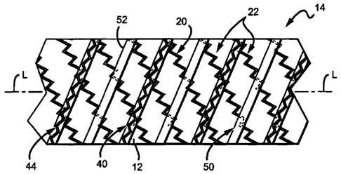
[0035] FIG. 4 illustrates an embodiment of a stent-graft 14 with a helix 20
disposed
about an outer surface of a substrate 12, the windings 22 of the helix forming
generally a first
angle with respect to the longitudinal axis L (however, it should be
appreciated that all of the
windings 22 may not form precisely the same angle and that angle variation
along the
longitudinal axis L is contemplated for certain embodiments). A covering 50
includes an
elongate strip of material (e.g., ePTFE) that is helically wound about the
longitudinal axis L to
create helical windings 52 that form generally a second angle with respect to
the longitudinal
axis L different from the first angle. For instance, in the embodiment shown,
each of the first
and second angles are generally oblique, one forming an acute angle and the
other forming an
obtuse angle, although in other embodiments each angle is generally acute (or
obtuse). A
support member 40, including spaced apart circumferential sections 44, is
coupled to the outer
surface of the covering 50 such that a winding 52 without a circumferential
section 44 coupled
thereto is disposed between adjacent circumferential sections 44. In some
embodiments, each
winding 52 of the covering has a circumferential section or other expandable
segment of the
support member coupled to an outer surface thereof, while in other
embodiments, two or more
windings 52 without an expandable segment of the support member are disposed
between
adjacent expandable segments (e.g., circumferential sections).
[0036] FIG. 5 shows an embodiment of a stent-graft 16 with a helix 20
disposed about an
outer surface of a substrate 12. A covering 60, including spaced apart annular
rings 62 and one
or more longitudinal strips 64, are disposed over portions of the helix 20 and
substrate 12. The
annular rings 62 may form an oblique angle with the longitudinal axis L, as
shown, or may be
disposed generally perpendicular to the longitudinal axis L. The longitudinal
strip(s) 62 are
disposed transverse to the annular rings 62 and, as shown, generally parallel
to the longitudinal
axis L, although in some embodiments, the longitudinal strips also form an
oblique angle with
the longitudinal axis L. A support member 40, including a plurality of
circumferential sections
46, is coupled to the covering 60 by coupling circumferential sections 46 to
the outer surface of
select annular rings 62 in a predetermined pattern. For example, as shown, the
pattern is two
14
CA 02691064 2014-11-26
adjacent circumferential sections 46 attached to two adjacent annular rings
62, followed
by two adjacent annular rings 62 without a circumferential section 46, etc. Of
course,
other patterns, such as those discussed above, are also possible and within
the scope of the
invention. The longitudinal strip(s) 64 may be disposed over the helix 20
prior to the
disposition of the annular rings 62, subsequent to the disposition of the
annular rings 62
and/or support member, or during the disposition of the annular rings 62 in
any woven-
type pattern (e.g., the longitudinal strip 64 may be alternately disposed
under an annular
ring 62 and over an adjacent annular ring). The longitudinal strips 64 may be
placed
under tension during disposition thereof. Other embodiments of stent-grafts
with strips
and bands are set forth in USPN 6,558,414 to Layne.
[0037] The coverings 50, 60 in FIGS. 4 and 5 are preferably made of ePTFE
and,
respectively, can be attached to an underlying ePTFE substrate 12 through the
application
of heat and/or pressure, and/or other methods, as described, for example, in
USPN
6,124,523 to Banas et al. Adhesives and/or solvents may also be used instead
of, or in
conjunction with, the aforementioned attachment methods. For example, a
polymer
coating (e.g., a urethane resin, silicone, FEP, combinations thereof, etc.)
could be disposed
on sides of the helix 20 to contact both the substrate and the covering when
assembled
together. Thereafter, the assembly can be soaked in a solvent for bonding.
Also, the helix
20 could be sutured to the substrate at various locations along the length
thereof. In one
embodiment, the substrate 12 is initially unsintered ePTFE and is located over
a mandrel
for positioning of the helix 20 and covering, which may be sintered or
partially sintered.
The assembly is then heated to sinter the substrate to the covering (e.g., 360
degrees C for
minutes). Prior to heating, the assembly may be subject to pressures to force
the
separate layers together (e.g., by wrapping with a tape). The support member
may be
coupled to the covering during or after this process.
[0038] In one embodiment, the materials for the stent-graft include ePTFE
for the
substrate, shape memory material for the helix and support member, and a
covering
knitted or woven with high strength polymer fibers such as ultra high
molecular weight
polyethylene fibers (e.g., Spectra , Dyneema Purity , etc.) or aramid fibers
(e.g.,
Technora , etc.). In one method of assembly, the substrate is positioned over
a mandrel
and the helix 20 is located thereover. The
CA 02691064 2009-12-08
WO 2009/002827
PCT/US2008/067630
covering is then disposed over the helix, accordingly positioned with respect
to the helix and
substrate, and placed under tension (e.g., proximal and distal ends of the
covering are pulled in
opposite directions) and clamped or otherwise fixed in place. The stent-graft
60 in its assembled
form is then preferably contacted with a polymeric adhesive, such as
polyurethane, to bond the
covering to the helix and/or the substrate. Optionally, the polymeric adhesive
can be activated
by a solvent, such as tetrahydrofuran (THF). Other modes of attachment (e.g.,
resin, sutures,
heat, pressure, etc.) may also be used in conjunction with the solvent to
assist in bonding.
Adhesives and/or solvents, as discussed above, may also be used to couple the
support member
to the covering while the helix is being bonded to the covering and/or
substrate or at some point
thereafter.
100391 In certain embodiments, the helix and support member include a self-
expanding
material and are arranged over the substrate in an expanded configuration
defining an expanded
perimeter of the stent-graft. In one embodiment of treating a blood vessel, a
stent-graft including
a self-expanding helix and support member is first compressed, the helix and
support member
collapsing to a collapsed configuration with a collapsed perimeter smaller
than the expanded
perimeter. A constraining sheath, which may be a component of a delivery
system, is positioned
over the stent-grall to maintain the helix and support member in the collapsed
configuration and
the sheath is delivered intraluminally in a patient to a predetermined region
of a blood vessel.
The constraining sheath is then removed from the stent-graft, allowing the
helix and support
member to expand. A balloon can optionally be inserted and inflated thereafter
to ensure contact
of the stent-graft with the blood vessel wall and positioning of the stent-
graft in the blood vessel.
In other embodiments, the helix and/or support member include a balloon
expandable material
and are arranged over the substrate in an original or non-expanded
configuration with a original
perimeter. In one embodiment of treating a blood vessel, a stent-graft
including a balloon
expandable helix and/or support member is positioned over a length of a
balloon on a balloon
catheter, which may be a component of a delivery system (e.g. the balloon
catheter may be
coaxially disposed in an outer sheath). The balloon catheter/delivery system
is inserted
intraluminally in a patient to a predetermined region of a blood vessel and
the balloon is then
inflated to expand the stent-graft, the helix and support member expanding to
an expanded
configuration with an expanded perimeter larger than the original perimeter.
After positioning is
confirmed, the balloon is deflated and the balloon catheter removed from the
blood vessel. The
16
CA 02691064 2014-11-26
helix and support member, whether balloon-expandable, self-expandable, or a
combination
thereof, may include a bio-resorbable material, as set forth above,
104340J The invention
has been described and specific examples have been portrayed.
While the invention has been described in terms of particular variations and
illustrative figures,
those of ordinary skill in the art will recognize that the invention is not
limited to the variations
or figures described, In addition, where methods and steps described above
indicate certain
events occurring in certain order, those of ordinary skill in the art will
recognize that the ordering
of certain steps may be modified and that such modifications are in accordance
with the
variations of the invention. Additionally, certain of the steps may be
performed concurrently in a
parallel process when possible, as well as performed sequentially as described
above,
17