Language selection

Search

Patent 2691114 Summary

Third-party information liability

Some of the information on this Web page has been provided by external sources. The Government of Canada is not responsible for the accuracy, reliability or currency of the information supplied by external sources. Users wishing to rely upon this information should consult directly with the source of the information. Content provided by external sources is not subject to official languages, privacy and accessibility requirements.

Claims and Abstract availability

Any discrepancies in the text and image of the Claims and Abstract are due to differing posting times. Text of the Claims and Abstract are posted:

  • At the time the application is open to public inspection;
  • At the time of issue of the patent (grant).
(12) Patent: (11) CA 2691114
(54) English Title: METHOD FOR MEASURING A TRACK POSITION
(54) French Title: PROCEDE DE MESURE DE GEOMETRIE DE VOIE
Status: Granted
Bibliographic Data
(51) International Patent Classification (IPC):
  • E01B 35/00 (2006.01)
(72) Inventors :
  • THEURER, JOSEF (Austria)
  • LICHTBERGER, BERNHARD (Austria)
(73) Owners :
  • FRANZ PLASSER BAHNBAUMASCHINEN-INDUSTRIEGESELLSCHAFT M.B.H. (Austria)
(71) Applicants :
  • FRANZ PLASSER BAHNBAUMASCHINEN-INDUSTRIEGESELLSCHAFT M.B.H. (Austria)
(74) Agent: RICHES, MCKENZIE & HERBERT LLP
(74) Associate agent:
(45) Issued: 2015-07-21
(86) PCT Filing Date: 2008-06-16
(87) Open to Public Inspection: 2009-02-05
Examination requested: 2013-06-13
Availability of licence: N/A
(25) Language of filing: English

Patent Cooperation Treaty (PCT): Yes
(86) PCT Filing Number: PCT/EP2008/004812
(87) International Publication Number: WO2009/015728
(85) National Entry: 2009-12-16

(30) Application Priority Data:
Application No. Country/Territory Date
A 1197/2007 Austria 2007-07-31

Abstracts

English Abstract


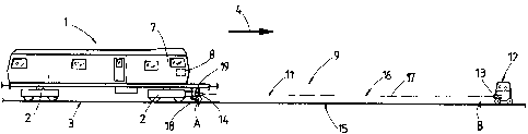
Measurement of a track position is carried out in successive measurement
sections (15), wherein the relative track position is registered in each case
with the
aid of a long chord (17), formed by a laser beam (16), which serves as
reference
line of a measuring system (9). During this, an angle enclosed by the two long

chords (17) of two successive measurement sections (15) is measured in order
to
thereby obtain a spatial curve reproducing the actual position of the track.


French Abstract

La présente invention concerne un procédé de mesure de la géométrie d'une voie par tronçons de mesure successifs (15). À cet effet, pour enregistrer la géométrie relative de la voie, on s'aide d'une corde géométrique (17) matérialisée par un rayon laser (16), utilisée comme alignement de référence d'un système de mesure (9). En l'occurrence, on mesure l'angle formé entre deux cordes géométriques (17) de deux tronçons de mesure successifs (15), ce qui permet de déterminer une courbe tridimensionnelle reflétant la position réelle de la voie.

Claims

Note: Claims are shown in the official language in which they were submitted.


5
Claims
1. A method for measuring a track position which is registered relative to
a long chord (17), formed by a laser beam (16), as reference line of a
measuring system (9) while forming successive measurement sections (15),
wherein a measurement section (15) is delimited, on the one hand, by the
start of a measuring run (point A) of a track measuring car (1) and, on the
other hand, by the conclusion of the measuring run (point B), after which a
satellite measuring trolley (12) which is stationary locally on the track
during
the measuring run is moved forward, while being distanced from the track
measuring car (1), for forming an adjoining measuring section (15) which is
finished with the conclusion (point C) of the next following measuring run of
the track measuring car (1), and wherein an angle a, enclosed by the two long
chords (17) of two successive measurement sections (15), is measured by an
inertial measuring system (19) registering space coordinates of the long
chords (17), and that individual measurement sections (15) are joined
together with the aid of the respective values of the angle measurement to
form a spatial location image.
2. A method according to claim 1, characterized in that a long-wave
compensation curve (10), yielding target position of the track, is computed
over several successive measurement sections (15).

Description

Note: Descriptions are shown in the official language in which they were submitted.


CA 02691114 2009-12-16
1
METHOD FOR MEASURING A TRACK POSITION
[0001] The invention relates to a method of measuring a track position in
successive measurement sections, wherein the relative track position is
registered in each case with the aid of a long chord, formed by a laser
beam, which serves as reference line of a measuring system.
[0002] A method of this type is known from US 7 050 926, wherein a track
measuring car with a laser receiver is moved in the direction towards a
satellite trolley standing still in place. During this, a laser beam is traced

which is emitted by a laser sender positioned on the satellite trolley. The
correction values determined for the track are recorded and relayed to a
tamping machine for carrying out a track position correction.
[0003] From US 5 090 329, a track measurement is known which is executed
with a measuring system associated with a tamping machine. Said
measuring system comprises an independently mobile satellite trolley
positioned in front of the tamping machine in the working direction, the
trolley having a laser sender. Associated with the tamping machine is a
laser receiver which is situated at a front end of a machine-specific
reference system.
[0004] For detecting the position of a fixed point, the satellite trolley is
placed in
proximity to the same, and a long chord formed by the laser sender is
brought into a target position. The tamping machine then works in the
direction towards the satellite trolley which is standing still.
Subsequently, the satellite trolley is moved to the next fixed point, and a
long chord is formed anew.

CA 02691114 2015-01-06
2
[0005] It is the object of the present invention to create a method of the
type
mentioned at the beginning with which it is possible to optimise the
track position measurement, particularly in track curves, even when
fixed point values are missing.
[0006] According to the invention, this object is achieved with a method of
the specified kind in that an angle a enclosed by the two long chords
of two successive measurement sections is measured.
[0007] With such an angle measurement, it is now possible to obtain a
cohesive position location image of the spatial position of the entire
track curve, even in track curves without fixed point data. The special
advantage now lies in the fact that, for correction of the actual position
of the track curve, it is possible to carry out a long-wave fault
compensation encompassing several measurement sections.
Additionally, it is alternatively possible, in connection with a
subsequent registration of fixed points, to achieve an absolute
position and marking of the track.
[0007a] Accordingly, in one aspect the present invention resides in a method
for measuring a track position which is registered relative to a long
chord, formed by a laser beam, as reference line of a measuring
system while forming successive measurement sections, wherein a
measurement section is delimited, on the one hand, by the start of a
measuring run (point A) of a track measuring car and, on the other
hand, by the conclusion of the measuring run (point B), after which a

CA 02691114 2015-01-06
2a
satellite measuring trolley which is stationary locally on the track
during the measuring run is moved forward, while being distanced
from the track measuring car, for forming an adjoining measuring
section which is finished with the conclusion (point C) of the next
following measuring run of the track measuring car, and wherein an
angle a, enclosed by the two long chords of two successive
measurement sections, is measured by an inertial measuring system
registering space coordinates of the long chords, and that individual
measurement sections are joined together with the aid of the
respective values of the angle measurement to form a spatial location
image.
[0008] Further advantages of the invention become apparent from the
following description and drawings.
[0009] The invention will be described in more detail below with reference to
an embodiment represented in the drawing in which
[0010] Fig. 1 shows a schematic side view of a track measuring car with an
satellite trolley for surveying a measurement section, and
[0011] Figs. 2, 3 each show an image of two successive measurement
sections.

CA 02691114 2009-12-16
3
[0012] A track measuring car 1, shown in Fig. 1, is mobile via on-track
undercarriages 2 on a track 3 in a working direction 4. Located in a front
driver's cab 7 is a control- and computing unit 8.
[0013] A measuring system 9 for detecting the track position consists of a
laser
reference system 11. The latter comprises a satellite measuring trolley
12, mobile independently on the track 3, which has a laser sender 13.
Associated with the latter is a laser receiver 14 located on a front
measuring axle 18 of the track measuring car 1. An inertial measuring
system (IMU) 19 is also arranged on said measuring axle 18.
[0014] A measurement section 15 is delimited, on the one hand, by a point A at

which the track measuring car 1 starts tracing the track 3 with the aid of
a long chord 17 formed by a laser beam 16 of the laser sender 13.
On the other hand, the measurement section 15 is concluded (see point
B) as soon as the track measuring car 1, while continuously registering
actual position data, has arrived at the satellite measuring trolley 12
which is standing still in place.
[0015] Fig. 2 shows two successive measurement sections 15 of the track 3,
which are delimited by points A,B and B,C. Each measurement section
15 contains a long chord 17 and an actual position 20 of the track 3.
When the track measuring car 1 starts the measuring run at point A, the
spatial coordinates for point A are registered with the aid of the inertial
measuring system 19 and stored in the computing unit 8. After the
spatial coordinates for points B and C have also been registered, an
angle a is calculated which is enclosed by the two successive long
chords 17.

CA 02691114 2009-12-16
4
[0016] With this continual angle measurement, it is possible to compute, by
integration, the location image or the course of the position of the track 3
with regard to level, line and cant with the corresponding space
coordinates. The spatial actual position 20 of the track 3, which has thus
been determined and stretches over several measurement sections 15,
is then smoothened by calculation ¨ with regard to both the vertical and
lateral position ¨ by superimposition of a long-wave compensation curve
(see Fig. 3). In addition, it would be possible in further sequence to
compute a sliding spline over a length of 100 meters, for example. This
would have the effect that fault wave lengths of up to 100 meters could
be eliminated without problem. The compensation curve 10 yields the
actual position for a track position correction to be carried out later by a
tamping machine. The stored data can be relayed to a tamping machine
by means of a disc or by radio transmission, for example.
[0017] Parallel to surveying the track position, it is possible in an
advantageous
way to also carry out a survey of fixed points 6 which are integrated in
the found compensation curve 10.

Representative Drawing
A single figure which represents the drawing illustrating the invention.
Administrative Status

For a clearer understanding of the status of the application/patent presented on this page, the site Disclaimer , as well as the definitions for Patent , Administrative Status , Maintenance Fee  and Payment History  should be consulted.

Administrative Status

Title Date
Forecasted Issue Date 2015-07-21
(86) PCT Filing Date 2008-06-16
(87) PCT Publication Date 2009-02-05
(85) National Entry 2009-12-16
Examination Requested 2013-06-13
(45) Issued 2015-07-21

Abandonment History

There is no abandonment history.

Maintenance Fee

Last Payment of $473.65 was received on 2023-04-06


 Upcoming maintenance fee amounts

Description Date Amount
Next Payment if small entity fee 2024-06-17 $253.00
Next Payment if standard fee 2024-06-17 $624.00

Note : If the full payment has not been received on or before the date indicated, a further fee may be required which may be one of the following

  • the reinstatement fee;
  • the late payment fee; or
  • additional fee to reverse deemed expiry.

Patent fees are adjusted on the 1st of January every year. The amounts above are the current amounts if received by December 31 of the current year.
Please refer to the CIPO Patent Fees web page to see all current fee amounts.

Payment History

Fee Type Anniversary Year Due Date Amount Paid Paid Date
Application Fee $400.00 2009-12-16
Maintenance Fee - Application - New Act 2 2010-06-16 $100.00 2009-12-16
Registration of a document - section 124 $100.00 2009-12-30
Maintenance Fee - Application - New Act 3 2011-06-16 $100.00 2011-04-18
Maintenance Fee - Application - New Act 4 2012-06-18 $100.00 2012-04-17
Maintenance Fee - Application - New Act 5 2013-06-17 $200.00 2013-04-16
Request for Examination $800.00 2013-06-13
Maintenance Fee - Application - New Act 6 2014-06-16 $200.00 2014-04-14
Maintenance Fee - Application - New Act 7 2015-06-16 $200.00 2015-04-21
Final Fee $300.00 2015-04-24
Maintenance Fee - Patent - New Act 8 2016-06-16 $200.00 2016-04-15
Maintenance Fee - Patent - New Act 9 2017-06-16 $200.00 2017-04-19
Maintenance Fee - Patent - New Act 10 2018-06-18 $250.00 2018-04-16
Maintenance Fee - Patent - New Act 11 2019-06-17 $250.00 2019-04-09
Maintenance Fee - Patent - New Act 12 2020-06-16 $250.00 2020-04-17
Maintenance Fee - Patent - New Act 13 2021-06-16 $255.00 2021-04-16
Back Payment of Fees 2022-04-27 $0.51 2022-04-27
Maintenance Fee - Patent - New Act 14 2022-06-16 $254.49 2022-04-27
Maintenance Fee - Patent - New Act 15 2023-06-16 $473.65 2023-04-06
Owners on Record

Note: Records showing the ownership history in alphabetical order.

Current Owners on Record
FRANZ PLASSER BAHNBAUMASCHINEN-INDUSTRIEGESELLSCHAFT M.B.H.
Past Owners on Record
LICHTBERGER, BERNHARD
THEURER, JOSEF
Past Owners that do not appear in the "Owners on Record" listing will appear in other documentation within the application.
Documents

To view selected files, please enter reCAPTCHA code :


To view images, click a link in the Document Description column. To download the documents, select one or more checkboxes in the first column and then click the "Download Selected in PDF format (Zip Archive)" or the "Download Selected as Single PDF" button.

List of published and non-published patent-specific documents on the CPD .

If you have any difficulty accessing content, you can call the Client Service Centre at 1-866-997-1936 or send them an e-mail at CIPO Client Service Centre.


Document
Description 
Date
(yyyy-mm-dd) 
Number of pages   Size of Image (KB) 
Maintenance Fee Payment 2020-04-17 1 24
Maintenance Fee Payment 2021-04-16 1 27
Maintenance Fee Payment 2022-04-27 1 30
Letter of Remission 2022-10-19 2 182
Abstract 2009-12-16 1 13
Claims 2009-12-16 1 30
Drawings 2009-12-16 1 14
Description 2009-12-16 4 145
Representative Drawing 2010-03-04 1 5
Cover Page 2010-03-04 1 34
Claims 2015-01-06 1 30
Description 2015-01-06 5 168
Representative Drawing 2015-07-08 1 4
Cover Page 2015-07-08 1 34
Correspondence 2010-03-01 1 16
PCT 2009-12-16 3 145
Assignment 2009-12-16 5 163
Assignment 2009-12-30 3 95
Fees 2011-04-18 1 51
Fees 2012-04-17 1 53
Fees 2013-04-16 1 56
Prosecution-Amendment 2013-06-13 1 56
Fees 2014-04-14 1 52
Prosecution-Amendment 2014-07-30 3 89
Prosecution-Amendment 2015-01-06 7 270
Correspondence 2015-04-24 1 56
Fees 2015-04-21 1 53