Sélection de la langue

Search

Sommaire du brevet 2691114 

Énoncé de désistement de responsabilité concernant l'information provenant de tiers

Une partie des informations de ce site Web a été fournie par des sources externes. Le gouvernement du Canada n'assume aucune responsabilité concernant la précision, l'actualité ou la fiabilité des informations fournies par les sources externes. Les utilisateurs qui désirent employer cette information devraient consulter directement la source des informations. Le contenu fourni par les sources externes n'est pas assujetti aux exigences sur les langues officielles, la protection des renseignements personnels et l'accessibilité.

Disponibilité de l'Abrégé et des Revendications

L'apparition de différences dans le texte et l'image des Revendications et de l'Abrégé dépend du moment auquel le document est publié. Les textes des Revendications et de l'Abrégé sont affichés :

  • lorsque la demande peut être examinée par le public;
  • lorsque le brevet est émis (délivrance).
(12) Brevet: (11) CA 2691114
(54) Titre français: PROCEDE DE MESURE DE GEOMETRIE DE VOIE
(54) Titre anglais: METHOD FOR MEASURING A TRACK POSITION
Statut: Octroyé
Données bibliographiques
(51) Classification internationale des brevets (CIB):
  • E01B 35/00 (2006.01)
(72) Inventeurs :
  • THEURER, JOSEF (Autriche)
  • LICHTBERGER, BERNHARD (Autriche)
(73) Titulaires :
  • FRANZ PLASSER BAHNBAUMASCHINEN-INDUSTRIEGESELLSCHAFT M.B.H. (Autriche)
(71) Demandeurs :
  • FRANZ PLASSER BAHNBAUMASCHINEN-INDUSTRIEGESELLSCHAFT M.B.H. (Autriche)
(74) Agent: RICHES, MCKENZIE & HERBERT LLP
(74) Co-agent:
(45) Délivré: 2015-07-21
(86) Date de dépôt PCT: 2008-06-16
(87) Mise à la disponibilité du public: 2009-02-05
Requête d'examen: 2013-06-13
Licence disponible: S.O.
(25) Langue des documents déposés: Anglais

Traité de coopération en matière de brevets (PCT): Oui
(86) Numéro de la demande PCT: PCT/EP2008/004812
(87) Numéro de publication internationale PCT: WO2009/015728
(85) Entrée nationale: 2009-12-16

(30) Données de priorité de la demande:
Numéro de la demande Pays / territoire Date
A 1197/2007 Autriche 2007-07-31

Abrégés

Abrégé français

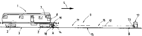
La présente invention concerne un procédé de mesure de la géométrie d'une voie par tronçons de mesure successifs (15). À cet effet, pour enregistrer la géométrie relative de la voie, on s'aide d'une corde géométrique (17) matérialisée par un rayon laser (16), utilisée comme alignement de référence d'un système de mesure (9). En l'occurrence, on mesure l'angle formé entre deux cordes géométriques (17) de deux tronçons de mesure successifs (15), ce qui permet de déterminer une courbe tridimensionnelle reflétant la position réelle de la voie.


Abrégé anglais


Measurement of a track position is carried out in successive measurement
sections (15), wherein the relative track position is registered in each case
with the
aid of a long chord (17), formed by a laser beam (16), which serves as
reference
line of a measuring system (9). During this, an angle enclosed by the two long

chords (17) of two successive measurement sections (15) is measured in order
to
thereby obtain a spatial curve reproducing the actual position of the track.

Revendications

Note : Les revendications sont présentées dans la langue officielle dans laquelle elles ont été soumises.


5
Claims
1. A method for measuring a track position which is registered relative to
a long chord (17), formed by a laser beam (16), as reference line of a
measuring system (9) while forming successive measurement sections (15),
wherein a measurement section (15) is delimited, on the one hand, by the
start of a measuring run (point A) of a track measuring car (1) and, on the
other hand, by the conclusion of the measuring run (point B), after which a
satellite measuring trolley (12) which is stationary locally on the track
during
the measuring run is moved forward, while being distanced from the track
measuring car (1), for forming an adjoining measuring section (15) which is
finished with the conclusion (point C) of the next following measuring run of
the track measuring car (1), and wherein an angle a, enclosed by the two long
chords (17) of two successive measurement sections (15), is measured by an
inertial measuring system (19) registering space coordinates of the long
chords (17), and that individual measurement sections (15) are joined
together with the aid of the respective values of the angle measurement to
form a spatial location image.
2. A method according to claim 1, characterized in that a long-wave
compensation curve (10), yielding target position of the track, is computed
over several successive measurement sections (15).

Description

Note : Les descriptions sont présentées dans la langue officielle dans laquelle elles ont été soumises.


CA 02691114 2009-12-16
1
METHOD FOR MEASURING A TRACK POSITION
[0001] The invention relates to a method of measuring a track position in
successive measurement sections, wherein the relative track position is
registered in each case with the aid of a long chord, formed by a laser
beam, which serves as reference line of a measuring system.
[0002] A method of this type is known from US 7 050 926, wherein a track
measuring car with a laser receiver is moved in the direction towards a
satellite trolley standing still in place. During this, a laser beam is traced

which is emitted by a laser sender positioned on the satellite trolley. The
correction values determined for the track are recorded and relayed to a
tamping machine for carrying out a track position correction.
[0003] From US 5 090 329, a track measurement is known which is executed
with a measuring system associated with a tamping machine. Said
measuring system comprises an independently mobile satellite trolley
positioned in front of the tamping machine in the working direction, the
trolley having a laser sender. Associated with the tamping machine is a
laser receiver which is situated at a front end of a machine-specific
reference system.
[0004] For detecting the position of a fixed point, the satellite trolley is
placed in
proximity to the same, and a long chord formed by the laser sender is
brought into a target position. The tamping machine then works in the
direction towards the satellite trolley which is standing still.
Subsequently, the satellite trolley is moved to the next fixed point, and a
long chord is formed anew.

CA 02691114 2015-01-06
2
[0005] It is the object of the present invention to create a method of the
type
mentioned at the beginning with which it is possible to optimise the
track position measurement, particularly in track curves, even when
fixed point values are missing.
[0006] According to the invention, this object is achieved with a method of
the specified kind in that an angle a enclosed by the two long chords
of two successive measurement sections is measured.
[0007] With such an angle measurement, it is now possible to obtain a
cohesive position location image of the spatial position of the entire
track curve, even in track curves without fixed point data. The special
advantage now lies in the fact that, for correction of the actual position
of the track curve, it is possible to carry out a long-wave fault
compensation encompassing several measurement sections.
Additionally, it is alternatively possible, in connection with a
subsequent registration of fixed points, to achieve an absolute
position and marking of the track.
[0007a] Accordingly, in one aspect the present invention resides in a method
for measuring a track position which is registered relative to a long
chord, formed by a laser beam, as reference line of a measuring
system while forming successive measurement sections, wherein a
measurement section is delimited, on the one hand, by the start of a
measuring run (point A) of a track measuring car and, on the other
hand, by the conclusion of the measuring run (point B), after which a

CA 02691114 2015-01-06
2a
satellite measuring trolley which is stationary locally on the track
during the measuring run is moved forward, while being distanced
from the track measuring car, for forming an adjoining measuring
section which is finished with the conclusion (point C) of the next
following measuring run of the track measuring car, and wherein an
angle a, enclosed by the two long chords of two successive
measurement sections, is measured by an inertial measuring system
registering space coordinates of the long chords, and that individual
measurement sections are joined together with the aid of the
respective values of the angle measurement to form a spatial location
image.
[0008] Further advantages of the invention become apparent from the
following description and drawings.
[0009] The invention will be described in more detail below with reference to
an embodiment represented in the drawing in which
[0010] Fig. 1 shows a schematic side view of a track measuring car with an
satellite trolley for surveying a measurement section, and
[0011] Figs. 2, 3 each show an image of two successive measurement
sections.

CA 02691114 2009-12-16
3
[0012] A track measuring car 1, shown in Fig. 1, is mobile via on-track
undercarriages 2 on a track 3 in a working direction 4. Located in a front
driver's cab 7 is a control- and computing unit 8.
[0013] A measuring system 9 for detecting the track position consists of a
laser
reference system 11. The latter comprises a satellite measuring trolley
12, mobile independently on the track 3, which has a laser sender 13.
Associated with the latter is a laser receiver 14 located on a front
measuring axle 18 of the track measuring car 1. An inertial measuring
system (IMU) 19 is also arranged on said measuring axle 18.
[0014] A measurement section 15 is delimited, on the one hand, by a point A at

which the track measuring car 1 starts tracing the track 3 with the aid of
a long chord 17 formed by a laser beam 16 of the laser sender 13.
On the other hand, the measurement section 15 is concluded (see point
B) as soon as the track measuring car 1, while continuously registering
actual position data, has arrived at the satellite measuring trolley 12
which is standing still in place.
[0015] Fig. 2 shows two successive measurement sections 15 of the track 3,
which are delimited by points A,B and B,C. Each measurement section
15 contains a long chord 17 and an actual position 20 of the track 3.
When the track measuring car 1 starts the measuring run at point A, the
spatial coordinates for point A are registered with the aid of the inertial
measuring system 19 and stored in the computing unit 8. After the
spatial coordinates for points B and C have also been registered, an
angle a is calculated which is enclosed by the two successive long
chords 17.

CA 02691114 2009-12-16
4
[0016] With this continual angle measurement, it is possible to compute, by
integration, the location image or the course of the position of the track 3
with regard to level, line and cant with the corresponding space
coordinates. The spatial actual position 20 of the track 3, which has thus
been determined and stretches over several measurement sections 15,
is then smoothened by calculation ¨ with regard to both the vertical and
lateral position ¨ by superimposition of a long-wave compensation curve
(see Fig. 3). In addition, it would be possible in further sequence to
compute a sliding spline over a length of 100 meters, for example. This
would have the effect that fault wave lengths of up to 100 meters could
be eliminated without problem. The compensation curve 10 yields the
actual position for a track position correction to be carried out later by a
tamping machine. The stored data can be relayed to a tamping machine
by means of a disc or by radio transmission, for example.
[0017] Parallel to surveying the track position, it is possible in an
advantageous
way to also carry out a survey of fixed points 6 which are integrated in
the found compensation curve 10.

Dessin représentatif
Une figure unique qui représente un dessin illustrant l'invention.
États administratifs

Pour une meilleure compréhension de l'état de la demande ou brevet qui figure sur cette page, la rubrique Mise en garde , et les descriptions de Brevet , États administratifs , Taxes périodiques et Historique des paiements devraient être consultées.

États administratifs

Titre Date
Date de délivrance prévu 2015-07-21
(86) Date de dépôt PCT 2008-06-16
(87) Date de publication PCT 2009-02-05
(85) Entrée nationale 2009-12-16
Requête d'examen 2013-06-13
(45) Délivré 2015-07-21

Historique d'abandonnement

Il n'y a pas d'historique d'abandonnement

Taxes périodiques

Dernier paiement au montant de 473,65 $ a été reçu le 2023-04-06


 Montants des taxes pour le maintien en état à venir

Description Date Montant
Prochain paiement si taxe applicable aux petites entités 2024-06-17 253,00 $
Prochain paiement si taxe générale 2024-06-17 624,00 $

Avis : Si le paiement en totalité n'a pas été reçu au plus tard à la date indiquée, une taxe supplémentaire peut être imposée, soit une des taxes suivantes :

  • taxe de rétablissement ;
  • taxe pour paiement en souffrance ; ou
  • taxe additionnelle pour le renversement d'une péremption réputée.

Les taxes sur les brevets sont ajustées au 1er janvier de chaque année. Les montants ci-dessus sont les montants actuels s'ils sont reçus au plus tard le 31 décembre de l'année en cours.
Veuillez vous référer à la page web des taxes sur les brevets de l'OPIC pour voir tous les montants actuels des taxes.

Historique des paiements

Type de taxes Anniversaire Échéance Montant payé Date payée
Le dépôt d'une demande de brevet 400,00 $ 2009-12-16
Taxe de maintien en état - Demande - nouvelle loi 2 2010-06-16 100,00 $ 2009-12-16
Enregistrement de documents 100,00 $ 2009-12-30
Taxe de maintien en état - Demande - nouvelle loi 3 2011-06-16 100,00 $ 2011-04-18
Taxe de maintien en état - Demande - nouvelle loi 4 2012-06-18 100,00 $ 2012-04-17
Taxe de maintien en état - Demande - nouvelle loi 5 2013-06-17 200,00 $ 2013-04-16
Requête d'examen 800,00 $ 2013-06-13
Taxe de maintien en état - Demande - nouvelle loi 6 2014-06-16 200,00 $ 2014-04-14
Taxe de maintien en état - Demande - nouvelle loi 7 2015-06-16 200,00 $ 2015-04-21
Taxe finale 300,00 $ 2015-04-24
Taxe de maintien en état - brevet - nouvelle loi 8 2016-06-16 200,00 $ 2016-04-15
Taxe de maintien en état - brevet - nouvelle loi 9 2017-06-16 200,00 $ 2017-04-19
Taxe de maintien en état - brevet - nouvelle loi 10 2018-06-18 250,00 $ 2018-04-16
Taxe de maintien en état - brevet - nouvelle loi 11 2019-06-17 250,00 $ 2019-04-09
Taxe de maintien en état - brevet - nouvelle loi 12 2020-06-16 250,00 $ 2020-04-17
Taxe de maintien en état - brevet - nouvelle loi 13 2021-06-16 255,00 $ 2021-04-16
Paiement des arriérés de taxes 2022-04-27 0,51 $ 2022-04-27
Taxe de maintien en état - brevet - nouvelle loi 14 2022-06-16 254,49 $ 2022-04-27
Taxe de maintien en état - brevet - nouvelle loi 15 2023-06-16 473,65 $ 2023-04-06
Titulaires au dossier

Les titulaires actuels et antérieures au dossier sont affichés en ordre alphabétique.

Titulaires actuels au dossier
FRANZ PLASSER BAHNBAUMASCHINEN-INDUSTRIEGESELLSCHAFT M.B.H.
Titulaires antérieures au dossier
LICHTBERGER, BERNHARD
THEURER, JOSEF
Les propriétaires antérieurs qui ne figurent pas dans la liste des « Propriétaires au dossier » apparaîtront dans d'autres documents au dossier.
Documents

Pour visionner les fichiers sélectionnés, entrer le code reCAPTCHA :


Pour visualiser une image, cliquer sur un lien dans la colonne description du document. Pour télécharger l'image (les images), cliquer l'une ou plusieurs cases à cocher dans la première colonne et ensuite cliquer sur le bouton "Télécharger sélection en format PDF (archive Zip)" ou le bouton "Télécharger sélection (en un fichier PDF fusionné)".

Liste des documents de brevet publiés et non publiés sur la BDBC .

Si vous avez des difficultés à accéder au contenu, veuillez communiquer avec le Centre de services à la clientèle au 1-866-997-1936, ou envoyer un courriel au Centre de service à la clientèle de l'OPIC.


Description du
Document 
Date
(yyyy-mm-dd) 
Nombre de pages   Taille de l'image (Ko) 
Paiement de taxe périodique 2020-04-17 1 24
Paiement de taxe périodique 2021-04-16 1 27
Paiement de taxe périodique 2022-04-27 1 30
Lettre de remise 2022-10-19 2 182
Abrégé 2009-12-16 1 13
Revendications 2009-12-16 1 30
Dessins 2009-12-16 1 14
Description 2009-12-16 4 145
Dessins représentatifs 2010-03-04 1 5
Page couverture 2010-03-04 1 34
Revendications 2015-01-06 1 30
Description 2015-01-06 5 168
Dessins représentatifs 2015-07-08 1 4
Page couverture 2015-07-08 1 34
Correspondance 2010-03-01 1 16
PCT 2009-12-16 3 145
Cession 2009-12-16 5 163
Cession 2009-12-30 3 95
Taxes 2011-04-18 1 51
Taxes 2012-04-17 1 53
Taxes 2013-04-16 1 56
Poursuite-Amendment 2013-06-13 1 56
Taxes 2014-04-14 1 52
Poursuite-Amendment 2014-07-30 3 89
Poursuite-Amendment 2015-01-06 7 270
Correspondance 2015-04-24 1 56
Taxes 2015-04-21 1 53