Note: Descriptions are shown in the official language in which they were submitted.
CA 02691284 2009-12-11
WO 2008/153459 PCT/SE2007/050415
1
PRESSURE EQUALIZING DEVICE, RECEPTACLE AND METHOD
TECHNICAL FIELD
The present invention concerns a pressure equalizing device comprising a fluid
container,
i.e. liquid and/or gas container, for attachment to a receptacle, such as a
vial, to permit
pressure equalization between the fluid container and the receptacle. The
present
invention also concerns a receptacle comprising such a pressure equalizing
device.
BACKGROUND OF THE INVENTION
When preparing and administering drugs care has be taken to minimize, or
preferably
eliminate the risk of exposing people, such as medical and pharmacological
personnel, to
toxic substances. Safety boxes, cabinets or isolators are often used to
prepare drugs to
reduce the risk of toxic substances leaking into breathable air. However, such
facilities
require a lot of space, they are non-portable and can be expensive to install,
maintain and
repair.
Some drugs must be dissolved or diluted before they are administered, which
involves
transferring a solvent from one container to a sealed vial containing the drug
in powder or
liquid form, by means of a needle for example. Drugs may be inadvertently
released into
the atmosphere in gas form or by way of aerosolization, during the withdrawal
of the
needle from the vial and while the needle is inside the vial if any pressure
differential
between the interior of the vial and surrounding atmosphere exists.
This problem may be eliminated or at least minimized by using a pressure
equalization
device that may be attached to a vial during the preparation of drugs. The
pressure
equalization device comprises a gas container in communication with the
interior of the
vial, which ensures that neither an increased pressure nor a vacuum can occur
inside the
vial when gas or liquid is injected into or withdrawn from the vial. The gas
container may
be filled with cleaned or sterilized air prior to its use to ensure that the
contents of the vial
do not become contaminated with air-borne particles such as dust, pollen,
mould or
bacteria and other undesirable substances.
CA 02691284 2009-12-11
2
SUMMARY OF THE INVENTION
An object of the present invention is to provide an improved pressure
equalizing device
comprising a fluid container, i.e. gas and/or liquid container, for attachment
to a
receptacle, such as a vial, to permit pressure equalization between the fluid
container and
the receptacle.
The present invention provides a pressure equalizing device comprising a fluid
container
and a flow channel that is arranged to provide fluid communication into or out
of the fluid
container when the pressure equalizing device is attached to the receptacle.
The
pressure equalizing device also comprises a fluid inlet that contains a one-
way valve that
permits fluid to flow into the fluid container via said fluid inlet and that
prevents fluid from
flowing out of the fluid container via said fluid inlet. The pressure
equalizing device also
comprises filter-receiving means that are arranged to permit fluid flowing
into or out of the
fluid container to be filtered when the filter-receiving means comprises a
filter.
The pressure equalizing device equalizes pressure in the fluid container and
the
receptacle by allowing filtered fluid to flow into or out of the receptacle
(depending on
whether the pressure is temporarily greater in the fluid container or the
receptacle). The
pressure equalizing device thereby provides a simple, closed system that
allows for safe
and reliable injection or withdrawal of substances, such as toxic drugs, into
or out of a
receptacle while at least minimizing, or eliminating the risk of the
substances
contaminating breathable air.
According to an embodiment of the invention the filter-receiving means
comprises a
removable or non-removable filter. As an example, a filter with the mesh size
0.2 pm may
be used to remove substantially all particles and micro organisms of that size
or larger.
The filter may be a sterilizing or aseptisizing filter, such as a particulate
air filter, such as a
high efficiency particulate air (HEPA) filter to remove gas-borne particles
such as dust,
pollen, mould or bacteria and thus eliminating or at least reducing the risk
of such gas-
borne particles from contaminating substances inside the vial. It should be
noted that the
pressure equalizing device may comprise a plurality of filters of the same
type or of
different types.
CA 02691284 2009-12-11
WO 2008/153459 PCT/SE2007/050415
3
According to an embodiment of the invention the filter-receiving means are
located
upstream or downstream of the one-way valve in the fluid inlet, which permits
fluid to be
filtered as it flows into the fluid container when the filter-receiving means
comprises a
filter. According to another embodiment of the invention the filter-receiving
means are
located in the flow channel, which permits fluid to be filtered as it flows
out of the fluid
container into the receptacle when the filter-receiving means comprises a
filter.
According to a further embodiment of the invention the fluid container is an
air container.
According to another embodiment of the invention the fluid inlet is arranged
to be in
communication with ambient, i.e. non-sterilized air. Since ambient air can be
cleaned on
site using a sterilizing or ascepticizing filter in the pressure equalizing
device, neither a
sterile environment, nor extra equipment, nor a supply of clean air is
necessary to fill the
fluid container with cleaned air. The pressure equalizing device according to
the present
invention may therefore be filled or replenished with cleaned fluid almost
anywhere, in a
simple manner and at low cost.
According to a further embodiment of the invention the fluid container
comprises a flexible
portion, such as a bladder, i.e. a portion comprising a flexible or expandable
material,
whereby the volume of said portion can be increased by drawing fluid into the
fluid
container and decreased by withdrawing fluid from the fluid container. The
fluid container
may however be at least partly constituted of a rigid, non-compressible
material.
According to an embodiment of the invention the one-way valve is integrally
formed with
the filter-receiving means or a filter.
According to another embodiment of the invention the filter-receiving means is
removable
from the fluid container.
According to a further embodiment of the invention the pressure equalizing
device
comprises connecting means, such as a bayonet coupling, luer lock or snap fit
mechanism, for attachment of the pressure equalizing device to an injector
such as a
syringe and/or connecting means, such as a snap fit mechanism for attachment
of the
pressure equalizing device to a receptacle.
CA 02691284 2009-12-11
WO 2008/153459 PCT/SE2007/050415
4
According to an embodiment of the invention at least part of the fluid
container is integrally
formed with the connecting means, from the same material for example, whereby
the
material may be a thermoplastic material, such as polyethylene or
polypropylene;
acrylonitrile butadiene styrene (ABS), polycarbonate, polyester or any other
suitable
material.
According to another embodiment of the invention the fluid container is
detachable from
the connecting means.
The present invention also concerns a receptacle that comprises a pressure
equalizing
device according to any of the embodiments of the invention.
According to an embodiment of the invention at least part of the pressure
equalizing
device is integrally formed with at least one component of the receptacle,
such as its cap
or sealing means.
The pressure equalizing device according to the present invention is intended
particularly,
but not exclusively for use as a pressure equalizing device during the
preparation or
administration of drugs.
BRIEF DESCRIPTION OF THE DRAWINGS
The present invention will hereinafter be further explained by means of non-
limiting
examples with reference to the appended figures where;
Figure 1 shows a pressure equalizing device according to an
embodiment of
the invention prior to attachment to a vial,
Figure 2 shows a pressure equalizing device according to an
embodiment of
the invention, after attachment to attachment to a vial,
Figure 3 shows part of a fluid container according to a first
embodiment of
the invention,
CA 02691284 2009-12-11
WO 2008/153459 PCT/SE2007/050415
Figures 4 & 5 show part of a pressure equalizing device according to a
second
embodiment of the invention,
Figures 6 & 7 show part of a fluid container according to a third
embodiment of
5 the invention,
Figures 8-10 show part of a pressure equalizing device according to a
fourth
embodiment of the invention, and
Figures 11-13 show part of a pressure equalizing device according to a
fifth
embodiment of the invention.
It should be noted that the drawings have not been drawn to scale and that the
dimensions of certain features have been exaggerated for the sake of clarity.
DETAILED DESCRIPTION OF EMBODIMENTS
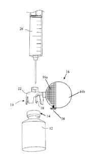
Figure 1 shows a pressure equalizing device 10 according to an embodiment of
the
invention prior to being attached to a vial 12 containing a solid, liquid or
gaseous
pharmaceutical, biological or veterinary substance. The vial 12 is sealed by
means of a
cap 14 and/or an elastomeric stopper or membrane. The pressure equalizing
device 10
comprises a gas container 16 having a variable volume. The gas container 16
comprises
a first portion 16a, such as a plastic parabola coupled to the main body of
the pressure
equalizing device 10, which comprises a relatively rigid material and a second
portion 16b
comprising a relatively flexible material, such as a thin, transparent plastic
film that is
attached to the first portion 16a in a gastight manner. For example, the gas
container 16
can be designed as a bellow which is compressible and extendable. The volume
of the
gas container 16 can thereby be increased and decreased. Although the device
illustrated
in figure 1 comprises a partly compressible gas container 16, in another
embodiment of
the invention the gas container 16 can comprise a cylinder and a piston
arranged therein
so as to enable the volume of the gas container to be changed.
Alternatively, the gas container 16 could be constituted by bellows that are
manually
expandable and contractible. The gas container 16 illustrated in figure 1 is
shown in a fully
inflated state. The thick dotted line in figure 2 illustrates the position of
the flexible portion
16b when the gas container 16 is in an evacuated and thus fully deflated
state.
CA 02691284 2009-12-11
WO 2008/153459 PCT/SE2007/050415
6
The gas container 16, which may have a volume of 1 cm3 or less, up to 1 litre
or more,
depending on the application or size of the receptacle, comprises at least one
gas inlet 20
containing a one-way valve and filter-receiving means. The pressure equalizing
device 10
comprises connecting means 22, such as a snap fit mechanism for attaching the
pressure
equalizing device 10 to the neck of a vial 12, which is 1-4 cm in diameter for
example and
a volume of 50 cm3, whereby the volume of the gas container may be 50 cm3 in
its fully
inflated state. The pressure equalizing device 10 may of course be dimensioned
to be
attached to receptacles of any size and volume. The pressure equalizing device
10 also
comprises a flow channel 18 that is arranged to provide gas communication
between the
gas container 16 and the interior of the vial 12 when the pressure equalizing
device 10 is
connected to the vial 12. Figure 1 also shows a syringe 26 that may be used to
inject fluid
into the vial 12 or to withdraw fluid therefrom.
Figure 2 shows the pressure equalizing device 10 shown in figure 1 when it has
been
detachably or non-detachably attached to the vial 12 and when the needle 26a
of the
syringe 26 has been inserted through the pressure equalizing device 10 into
the interior of
the vial 12. As the fluid is injected into the vial 12 or withdrawn from the
vial 12, the flow
channel 18 of the pressure equalizing device permits gas to flow from the
interior of the
vial 12 into the gas container 16 or from the gas container 16 to the vial 12,
and thereby
equalizes the pressure in the interior of the vial 12 and in the gas container
16. Gas may
enter the gas container 16 via the fluid inlet 20, however gas cannot exit the
gas container
16. This eliminates, or at least reduces the risk of any substance inside the
vial 12 being
released into the atmosphere in gas form or by way of aerosolization during
the insertion
or withdrawal of the needle 26a from vial 12 or while the needle 26a is
inserted in the vial
12. It also eliminates, or reduces the risk of the vial 12 deforming due to
the increased
pressure inside the vial 12, whereby such deformation may cause leakage of the
vial's
contents due to separation of the vial's cap 14 from the vial's walls for
example.
Figure 3 shows the rigid, incompressible part 16a of the gas container 16
shown in figures
1 and 2. This part 16a of the gas container comprises the gas inlet 20 that
contains a one-
way valve 28 that permits gas to flow into the gas container 16 via the gas
inlet 20 and
that prevents gas from flowing out of the gas container 16 via the gas inlet
20. The gas
inlet 20 also comprises filter-receiving means 30 that are located upstream of
the one-way
valve 28. The gas inlet 20 is arranged to be in communication with ambient
air. When a
filter is placed in the filter-receiving means 30 ambient air is filtered as
it flows into the gas
CA 02691284 2009-12-11
WO 2008/153459 PCT/SE2007/050415
7
container 16. The filter may be any suitable commercially available filter,
such as a
particulate air filter having a pore size of 0.2 u.m. In the illustrated
embodiment the one-
way valve 28 is integrally formed with filter-receiving means 30. This
integrated unit may
be detachable or non-detachable from the gas container 16. The gas container
16 also
comprises a flow channel 18 that provides a gas communication channel into and
out of
the gas container 16.
The embodiment illustrated in figure 3 includes an integrated one-way valve 28
and filter-
receiving 30 unit that is slidably mounted in the plastic parabola 16a of the
gas container.
The one-way valve 28 comprises an elastic sheath 28a that is arranged to cover
an
opening 28b and to uncover the opening 28b in its open position. When the
pressure
outside the gas container 16 exceeds the pressure inside the gas container 16,
the
integrated one-way valve 28 and filter-receiving means 30 unit is pushed
radially inwards
in a direction towards the interior of the gas container 16, which causes the
elastic sheath
28a to abut against a stopper 28c and retract, uncovering the opening 28b and
allowing
filtered air into the gas container 16. Conversely, when the pressure inside
the gas
container 16 exceeds the pressure outside the gas container 16 the integrated
one-way
valve 28 and filter-receiving means 30 unit is arranged to be pushed radially
outwards in a
direction out of the gas container 16, whereby the elastic sheath 28a extends
and covers
the opening 28b preventing any more gas from entering the gas container 16 via
the air
inlet 20. The one way valve 28 is arranged to draw ambient air through the
filter 30 and
out of the opening 28b into the gas container 16 when the pressure inside the
gas
container 16 falls below a predetermined pressure, such as atmospheric
pressure in order
to keep the pressure inside the vial 12 in equilibrium with the pressure on
the exterior of
the vial 12. Alternatively, the one way valve 28 could be arranged to be
opened and
closed manually.
Figures 4 and 5 show part of a pressure equalizing device 10 according to a
second
embodiment of the invention. The pressure equalizing device comprises
connecting
means 22 for attachment to a receptacle and connecting means 23, namely a
bayonet
coupling, for attachment to an injector, such as a syringe, and a gas
container 16
comprising a plastic parabola 16a and a flexible portion (not shown) that is
attached to the
plastic parabola 16a. A filter may be placed in the filter-receiving means 30
to filter gas
entering the gas container 16 via the air inlet 20 (that is hidden behind the
filter-receiving
means 30 in figures 4 and 5).
CA 02691284 2009-12-11
WO 2008/153459 PCT/SE2007/050415
8
The filter-receiving means 30 are either integrally formed with the plastic
parabola 16a of
the gas container 16, by a blow moulding or vacuum forming process for
example, or are
attached to the inner surface of the plastic parabola 16a, by a continuous
welding
process, such as ultrasound welding, for example. Ultrasound is used to
generate internal
friction in the plastic of the parabola 16a and the filter-receiving means 30
and thereby
heat the parabola 16a and the filter-receiving means 30. The heated surfaces
are then
joined together by application of pressure. A filter may be permanently
attached to the
filter-receiving means 30 using ultrasound welding.
The filter and filter-receiving means 30 should be arranged to ensure that a
flexible portion
is substantially uniformly inflated so that no part of it is excessively
stretched during the
inflation thereof. The filter may, for example, be arranged at an angle to the
direction of
incoming gas as shown in figures 4 and 5, rather than being arranged
perpendicularly to
the direction of incoming gas. A second filter-receiving means may be placed
in the flow
channel 18 to enable fluid passing between the vial 12 and the gas container
16 to be
filtered.
Figure 6 shows an exploded view of part of a pressure equalizing device 10
according to
a third embodiment of the invention. The gas container 16 comprises a parabola
16a and
a flexible portion 16b comprising a thin transparent film. The gas container
16 comprises
an air inlet 20 and a one-way valve 28 is located in the air inlet 20. Figure
7 shows the
pressure equalizing device 10 of figure 6 when in use. Gas flows into the gas
container 16
in the direction of the arrows in figure 7, namely through the openings in
part 24 of the gas
container 16, through a filter 34 into the air inlet 20 via radial channels
and past the one-
way valve 28 into the interior of the gas container 16. The part 24 comprising
the
openings in the illustrated embodiment may be arranged to be removable from
the gas
container 16 or it may be fixedly attached thereto, by means of adhesion or
welding for
example. Figure 7 shows that filter-receiving means 30 may be placed at the
mouth of the
flow channel 18 that provides gas communication into or out of the gas
container and/or at
any other position along the flow channel 18.
Figures 8-10 show part of a pressure equalizing device 10 according to a
fourth
embodiment of the invention. The pressure equalizing device 10 comprises a gas
container comprising a parabola 16a and means 22 for connecting the pressure
CA 02691284 2009-12-11
WO 2008/153459 PCT/SE2007/050415
9
equalizing device 10 to an receptor. The gas container 16 may be detachable
from the
connecting means 22. The gas container 16 is for example attached to the
connecting
means 22 by means of a bayonet coupling or any other releasable coupling
means. Filter-
receiving means 30 are placed in between the gas container 16 and the
connecting
means 22.
Figures 11-13 show part of a pressure equalizing device 10 according to a
fifth
embodiment of the invention. The pressure equalizing device 10 comprises a
parabola
16a and connecting means 23 for attaching the pressure equalizing device 10 to
an
injector, such as a syringe. The parabola 16a is integrally formed with the
connecting
means 22 and 23 in the illustrated embodiment. The pressure equalizing device
10
comprises an insert 36 comprising filter-receiving means 30 and a one-way
valve 28. The
insert 36 is removably or non-removably attached to the inside of the parabola
16a and
may be provided with guiding means, to facilitate positioning of the filter-
receiving means
30 in the flow channel 18 and/or the one-way valve 28 in the air inlet 20.
Further modifications of the invention within the scope of the claims would be
apparent to
a skilled person. For example, the gas container may be of any shape and size
and may
be located in any suitable position with respect to a receptacle when a
pressure
equalizing device is attached to a receptacle.