Note: Descriptions are shown in the official language in which they were submitted.
CA 02691332 2010-01-29
Atty's 24643
WALKING-BEAM CONVEYOR
SPECIFICATION
FIELD OF THE INVENTION
The present invention relates to a walking-beam
conveyor. More particularly this invention concerns such a
conveyor for the stepped transport of a succession of large
objects.
BACKGROUND OF THE INVENTION
A walking-beam conveyor for the stepped transport of
strip coils or coils of sheet metal, sheet packets or similar
transport objects has a beam that can be raised and lowered by
lifters as well as displaced in the transport direction relative
to at least one support rail by at least one travel drive. It
also has two wheel assemblies or stools. The beam is typically
coupled to a following walking-beam conveyor.
A walking-beam conveyor of this type has several beams
of the same conveyor type arranged one behind the other in the
transport direction and coupled to one another, as known from US
6,650,963. The beams are moved jointly forward and backward in
steps via their travel drives. The individual conveyors are
coupled to one another by respective connecting rods. The beam
or beams can thereby be raised and lowered by their lifters so
that the sheet-metal coils bearing on lateral bearing surfaces
- 1 - ENGLISCHE UBERSETZUNG WORD.DOC
CA 02691332 2010-01-29
Atty's 24643
can be moved in a steps or incrementally displaced along in the
transport direction.
With a walking-beam conveyor known from DE 12 94 281,
several beams arranged one after the other in the travel
direction are connected to one another via couplings only
transmitting the drive motion, otherwise permitting an optional
raising or lowering independently of one another. The lifters
assigned to each beam are arranged on a respective stool that is
moved via support wheels on a rail arrangement in the transport
direction or longitudinal direction. At least two stools, which
have two drive axles, are provided for each beam.
Since each individual beam is designed for a specific
number of coils with a specific geometry and thus for a fixed
maximum weight, with the known walking-beam conveyors with an
increase in the number of coils or with the transport of coils
larger in diameter and heavier, several of these beams are
coupled to one another. The beams with their frames are jointly
moved via the suspension or the coupling on the lines of support
rails in the transport direction, but can be raised and lowered
independently of one another. The coupling of several completely
independent beams for the stepped transport of an increased total
load is hereby indispensable, since the individual components of
a beam are coordinated with one another such that an increase in
the number of coils or an increase in weight of the individual
coils would lead to a complete reworking or adjustment of the
individual beams.
An essential component of the beam is thus its frame.
Usually two travel drives or stools with respective axles and
- 2 - ENGLISCHE UBERSETZUNG WORD.DOC
CA 02691332 2010-01-29
Atty's 24643
wheels are installed for each beam. The stools are designed for
a specific maximum axle load that must not be exceeded. An
increase in the axial load by additional coils or heavier coils
would hence require a change of the rail systems for the wheels
in addition to a new construction of the frame.
OBJECTS OF THE INVENTION
It is therefore an object of the present invention to
provide an improved walking-beam conveyor.
Another object is the provision of such an improved
walking-beam conveyor that overcomes the above-given
disadvantages, in particular that can be variably expanded in a
simple and cost-effective manner for the transport of a greater
number of coils of sheet metal.
SUMMARY OF THE INVENTION
A walking-beam conveyor for stepped transport of heavy
objects has according to the invention an upstream beam extending
in a horizontal transport direction and adapted to carry a
plurality of the objects. A pair of horizontally spaced upstream
supports underneath the upstream beam are associated with
respective vertical and horizontal upstream drives for raising
the upstream beam relative to the supports, shifting the upstream
beam a step downstream, lowering the upstream beam, and shifting
the upstream beam a step upstream to shift the objects on the
upstream downstream in steps. In accordance with the invention a
- 3 - ENGLISCHE UBERSETZUNG WORD.DOC
CA 02691332 2010-01-29
Atty's 24643
downstream beam immediately downstream of the upstream beam has
an upstream end juxtaposed with a downstream end of the upstream
beam with a single downstream support under the downstream beam.
A pivot connects the downstream end of the upstream beam to the
upstream end of the downstream beam for joint synchronous
vertical and horizontal movement of the two beams.
Thus, in contrast to a second independent beam, the
downstream beam does not perform any independent sequences of
motions, but is synchronized with the sequences of motions of the
upstream beam.
To transport the coils, beams can hereby be used which
are different in their dimensions and their bearing capacity and
constructed to be adapted to the transport tasks in a modular and
variable manner, so that in particular from load and costs
aspects, an optimum combination of upstream beams and downstream
beam depending on the number of coils and the corresponding coil
weight is always possible. The present or existing walking beam
conveyor installations do not need to be altered or converted in
any way, in particular a further complete beam with two stools is
dispensable. Coupling the conveyor via a pivot or spherical
plain bearing synchronizes the system despite the total of three
stools or wheel assemblies.
A preferred embodiment of the invention provides that
the downstream has its own vertical drive. This means that the
downstream beam does not have its own drive for horizontal
transport movement and is moved jointly with the upstream beam on
which, for example, a horizontal cylinder acts. In contrast to
the upstream beam, the downstream beam conveyor by itself would
- 4 - ENGLISCHE UBERSETZUNG WORD.DOC
CA 02691332 2010-01-29
Atty''s 24643
be passive. Through the pivot connection of the downstream beam
or conveyor to the upstream beam, preferably by a simple bearing
transferring horizontal as well as vertical forces, the
downstream beam is passively synchronized despite the single
support stool. In contrast, an elongated upstream beam with, for
example, three stools would be passive. The lifter of the
downstream beam can be embodied, for example, as a
piston/cylinder unit or as an eccentric raising gear and
synchronized with the raising and lowering movements of the
upstream beam. For example, with an eccentric raising gear which
is or are embodied in the stools, namely as the eccentric wheel
containing the bearing of the wheels, through a coupling rod that
connects the crank wheels to one another. For the vertical lift,
a lift cylinder is hereby pivoted on the one hand at an off-
center position of an eccentric wheel and on the other hand on
the upstream beam or on the beam of the downstream beam.
The combination of walking-beam conveyor and conveyor
with a single wheel assembly or stool and pivoted connection of
the downstream beam thereby also actively does not require a
cost-intensive second frame as would be the case with a complete
beam or any other conversion measures for the conveyor system.
BRIEF DESCRIPTION OF THE DRAWING
The above and other objects, features, and advantages
will become more readily apparent from the following description,
reference being made to the accompanying drawing in which:
- ENGLISCHE UBERSETZUNG WORD.DOC
CA 02691332 2010-01-29
Atty's 24643
FIG. 1 is a side view of a prior-art walking-beam
conveyor for five objects; and
FIGS. 2-4 are systems according to the instant
invention with different numbers of coils on the upstream and
downstream conveyors.
SPECIFIC DESCRIPTION
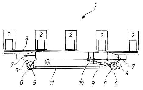
FIG. 1 shows a prior-art walking-beam conveyor 1 for
the stepped transport of in this case five sheet-metal coils 2.
This is a continuous conveyor that superimposes vertical and
horizontal movements to move the coils 2 with a succession of
identical steps.
The frame of the conveyor 1 is formed by two stools 3
and 4 each carried on a respective axle 5 journaled eccentrically
in a respective wheel 6. The wheels 6 are guided with the
horizontal movement or transport movement of the conveyor 1 on
unillustrated guide rails of a rail system within the conveyor.
Each of the two stools 3 and 4 carries a respective
lifter 7 that can raise and lower an upstream beam 8 carrying the
coils 2 relative to a stationary support P or instead and thus
optionally (Both variants being indicated at next to one another
in the illustrated embodiment.) the vertical movement can be
effected by eccentric lifters in each of the stools 3 and 4. To
this end, the stool 4 has a lift cylinder 9, which on the one
hand is pivoted off-center to an eccentric wheel carrying the
pivot of the respective wheel 6, and on the other hand to a
support 10 on the upstream beam 8. The eccentric wheels are
- 6 - ENGLISCHE UBERSETZUNG WORD.DOC
CA 02691332 2010-01-29
=Atty's 24643
coupled to one another via a connecting rod 11 for synchronous
rotation. Extension of the lift cylinder 9 rotates the eccentric
wheel to initiate vertical movement at the same time through the
eccentric wheel bearing. The horizontal travel drive of the
conveyor 1 is carried out, for example, by standard known
cylinder drives or motor drives such as shown schematically at D.
Stepped forward and backward motion and corresponding raising
and lowering of the conveyor 1, moves the coils 2 carried on the
upstream beam 8 in steps the desired conveyor direction C.
FIG. 2 shows a conveyor 12a of the same design as
described above for the prior-art conveyor 1. A downstream beam
or conveyor 14a is connected to the upstream conveyor 12a by a
pivot 13 embodied as plain bearing. The downstream conveyor 14a
has on its downstream end remote from the pivot 13 bearing only
one stool or wheel assembly 15, i.e. an axle 16 with wheels 17
connected thereto. A lifter 18 for raising and lowering a
downstream beam 19 bearing a coil 2 is provided above the stool
15. Here, too, an eccentric raising gear can optionally be
provided, as already explained above for FIG. 1, to which end a
cylinder 20 is provided on the stool 15 that for raising and
lowering the downstream beam 19 is connected to a support 21
thereon.
The eccentric wheel of the raising gear of the
downstream conveyor 14a is coupled via a link or connecting rod
22 to the connecting rod 11 of the upstream conveyor 12a for
synchronous movement. This means that the downstream conveyor
14a does not perform any raising and lowering movements
independently of the upstream conveyor 12a, but carries out
- 7 - ENGLISCHE UBERSETZUNG WORD.DOC
CA 02691332 2010-01-29
fitty's 24643
exactly the same synchronous sequences of motions as the upstream
conveyor 12a.
The advantage of the downstream conveyor 14a coupled by
a simple pivot 13 to the upstream conveyor 12a is that, in
contrast to a complete independent conveyor 1 or 12a when such a
complete beam of this type were necessary as a second beam due to
the load situation, only one stool 15 or one axle 16 is needed.
The pivot connection to the upstream conveyor 12a, gives the
downstream conveyor 14a the same solid positioning as the
upstream conveyor 12a carried on two stools 3 and 4.
As can be seen from FIG. 2, for better weight
distribution of the coils 2 that are heavier compared to FIG. 1,
the five coils 2 to be transported in FIG. 1 by a conveyor 1 with
the upstream conveyor 12a with the downstream conveyor 14a were
divided in the ratio of three (upstream conveyor 12a) to two
(downstream conveyor 14a).
In the embodiment according to FIG. 3, an upstream
conveyor 12b is loaded with four coils 2 and a downstream
conveyor 14b is loaded with two coils 2. The upstream conveyor
12b here has a greater length than the downstream conveyor 14b.
With the upstream conveyor 12b, its maximum carrying capacity
with respect to the number of coils as well as to maximum coil
weight is reached by loading with four coils 2. In this case,
for the stepped transport of additional coils 2 a downstream
conveyor 14b is pivoted on its downstream. This downstream
conveyor 14b is designed for conveying two coils 2.
With the upstream conveyor 12c with downstream conveyor
14c shown in FIG. 4, the upstream conveyor 12c has a shorter
8 - ENGLISCHE UBERSETZUNG WORD.DOC
CA 02691332 2010-01-29
Atty's 24643
length than the downstream conveyor 14c. The construction-
related carrying capacity of the upstream conveyor 12c is here
reached by loading with three coils 2, so that to transport three
further coils 2, the pivotally connected downstream conveyor 14c
has greater length and is thus designed in terms of the frame as
well in terms of raising technology for a higher load bearing.
As the embodiments according to FIGS. 2 through 4 show
that the pivotal connection of downstream conveyors 14a, 14b, and
14c of different lengths and/or built for different load-bearing
levels, creates a very variable conveyor system that can be
installed very easily on existing conveyor tracks without
conversion measures and in terms of load and cost aspects renders
possible at any time an optimum combination of upstream and
downstream beam depending on the coil weight and the number of
coils or the transport task to be carried out.
9 - ENGLISCHE UBERSETZUNG WORD.DOC