Note: Descriptions are shown in the official language in which they were submitted.
CA 02691351 2009-12-16
- 1 -
DESCRIPTION
USER EQUIPMENT TERMINAL, BASE STATION APPARATUS, AND
CHANNEL STATE INFORMATION COMMUNICATION METHOD
TECHNICAL FIELD
The present invention relates to a field
of mobile communications. More specifically, the
present invention relates to a user equipment
terminal, a base station apparatus, and a control
information communication method in a mobile
communication system.
BACKGROUND ART
In the field of mobile communications,
research and development on a next generation
communication system is rapidly progressing. In the
communication system considered as of now, from the
view point of broadening the coverage area while
reducing PAPR (Peak-to-Average Power Ratio), it is
proposed to use a single carrier scheme for uplink.
In this communication system, radio resources for
both uplink and downlink are properly assigned, as a
form of a shared channel which is shared by plural
users, according to communication conditions of
respective users and the like. More specifically, a
data signal of a user in uplink is transmitted on a
physical uplink shared channel (PUSCH). The terms
"channel" and "signal" may be used synonymously as
long as there is no fear of confusion. A data
signal of a user in downlink is transmitted on a
physical downlink shared channel (PDSCH).
Processing for determining assignment is
called scheduling. In order to properly perform
scheduling in uplink, each user equipment terminal
transmits a reference signal (also called a pilot
channel) to a base station and the base station
CA 02691351 2009-12-16
- 2 -
evaluates the uplink channel state based on
reception quality of the reference signal. In
addition, in order to perform scheduling in downlink,
the base station transmits a reference signal to the
user equipment terminal and the user equipment
terminal reports to the base station information
about the channel state (CQIs: Channel Quality
Indicators) based on reception quality of the
reference signal. Based on the CQIs reported from
each user equipment terminal, the base station
evaluates the downlink channel state to perform
scheduling in downlink. The results of scheduling
are transmitted to each user equipment terminal via
a downlink control signal. This control signal is
called a downlink Ll/L2 control signal.
There are two types of uplink control
signals: one is control information (called first
control information, for the sake of convenience)
that should be transmitted together with an uplink
data signal and the other is control information
(called second control information, for the sake of
convenience) that is transmitted irrespective of the
presence or absence of the uplink data signal. The
first control information includes information
necessary for demodulation of the data signal, such
as a modulation scheme, a channel coding rate, and
the like of the data signal. The second control
information includes CQI information of a downlink
channel, acknowledgement information (ACK/NACK) of a
downlink data signal, information about a resource
assignment request, and the like.
When a resource block (radio resource) is
assigned for transmitting an uplink data signal, the
first control information (and second control
information as necessary) is transmitted in the
resource block. On the other hand, when the uplink
data signal is not transmitted, it is considered
CA 02691351 2009-12-16
- 3 -
that the second control information is transmitted
using a dedicated resource (dedicated band). In the
following, an example of using the band is described
below.
Fig. 1 shows a configuration of an uplink
channel. Fig. 1 shows resources (plural resource
blocks) for transmitting the physical uplink shared
channel (PUSCH) as the uplink data signal, and
resources (corresponding to the dedicated band) for
a user to which resources for the PUSCH are not
assigned to transmit the uplink control signal. The
latter is called a physical uplink control channel
(PUCCH). In the shown example, one or more of four
resource blocks are assigned to users, a first
hopping control signal and a second hopping control
signal are provided in a certain transmission time
interval (subframe), and a third hopping control
signal and a fourth hopping control signal are
provided in the following subframe. Each hopping
control signal corresponds to the PUCCH. By
performing hopping with respect to time and
frequency in subframes, a greater diversity effect
can be obtained. Each of the first through fourth
hopping control signals may be occupied by one user
or may be multiplexed by plural users. This
transmission scheme of uplink control signals is
described in 3GPP, R1-071245.
DISCLOSURE OF INVENTION
[PROBLEM(S) TO BE SOLVED BY THE INVENTION]
When the L1/L2 control channel (first
through fourth hopping control signals) is
multiplexed by plural users without uplink data
transmission, it is considered that orthogonality
among the plural users is achieved using a CAZAC
sequence. The CAZAC sequence has a characteristic
in that a CAZAC code is orthogonal to a code with a
CA 02691351 2009-12-16
- 4 -
cyclic shift of the CAZAC code. Accordingly, when
the same CAZAC sequence is used among users and
different cyclic shifts are applied to the users,
orthogonality among the users can be achieved. Fig.
2 shows a configuration of the Ll/L2 control channel,
where the cyclic shift amount of zero (0) is applied
to a user #1 and the cyclic shift amount of 0 is
applied to a user #2.
In this manner, the Ll/L2 control channel
for users without uplink data transmission undergoes
block-modulation using the CAZAC code in order to
multiplex data for plural users. Thus, the number
of bits available for transmission per user is
determined in advance. For example, it is assumed
that ten symbols per user can be transmitted in the
subframe configuration shown in Fig. 2. When a QPSK
data modulation and the coding rate of 1/2 are used,
a user equipment terminal can transmit ten bits of
information for each subframe.
As described above, the Ll/L2 control
channel for users without uplink data transmission
includes CQI information, acknowledgement
information (ACK/NACK), information about a resource
assignment request, and the like. Regarding the CQI
information, the user equipment terminal may
transmit fine-grained CQIs for respective bands to
be scheduled according to an instruction from the
base station apparatus. In addition, the user
equipment terminal may transmit CQIs for respective
streams in the case of MIMO (multiple input multiple
output) transmission using plural antennas. In
these circumstances, the CQI information may exceed
the number of bits which can be transmitted in each
subframe.
For example, by increasing the coding rate,
for example (using the coding rate of 3/4, for
example), it is possible to increase the number of
CA 02691351 2009-12-16
- 5 -
bits which can be transmitted in each subframe. In
this case, however, a problem of degrading reception
quality may arise. For example, in W-CDMA (wideband
code division multiple access), CQI information is
repeatedly transmitted in the case where reception
quality is degraded.
In view of this problem, it is a general
object of the present invention to transmit channel
state information (CQI information) without
degrading reception quality.
[MEANS FOR SOLVING THE PROBLEM(S)]
In one aspect of the present invention,
there is provided a user equipment terminal for
estimating a channel state and transmitting, as
control information transmitted irrespective of a
presence or absence of an uplink data signal,
channel state information representing the estimated
channel state according to a single carrier scheme,
including:
an encoding unit configured to encode the
channel state information; and
a transmitting unit configured to transmit
the channel state information over plural
transmission time intervals.
In another aspect of the present invention,
there is provided a base station apparatus for
receiving, as control information transmitted
irrespective of a presence or absence of an uplink
data signal, channel state information representing
a channel state estimated by a user equipment
terminal, including:
a receiving unit configured to receive the
channel state information over plural transmission
time intervals;
a decoding unit configured to decode the
channel state information; and
a resource assigning unit configured to
CA 02691351 2009-12-16
- 6 -
assign resources based on the channel state
information.
In another aspect of the present invention,
there is provided a channel state information
communication method for use in a mobile
communication system using a single carrier scheme
for uplink, including the steps of:
by a user equipment terminal,
estimating a channel state;
encoding channel state information
representing the estimated channel state;
transmitting, as control information
transmitted irrespective of a presence or absence of
an uplink data signal, the channel state information
over plural transmission time intervals;
by a base station apparatus,
receiving the channel state information
over plural transmission time intervals;
decoding the channel state information;
and
assigning resources based on the channel
state information.
[ADVANTAGEOUS EFFECT OF THE INVENTION]
According to an embodiment of the present
invention, it is possible to transmit channel state
information without degrading reception quality.
BRIEF DESCRIPTION OF THE DRAWINGS
Fig. 1 shows a channel configuration used
in a mobile communication system.
Fig. 2 shows a multiplexing scheme among
users in an Ll/L2 control channel for users without
uplink data transmission.
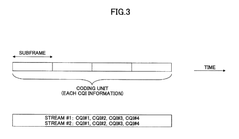
Fig. 3 shows a coding unit of a CQI
encoding method in accordance with a first
embodiment of the present invention.
Fig. 4 shows a flowchart of the CQI
CA 02691351 2009-12-16
- 7 -
encoding method in accordance with the first
embodiment of the present invention.
Fig. 5 shows a block diagram of a user
equipment terminal in accordance with the first
embodiment of the present invention.
Fig. 6 shows a block diagram of a base
station apparatus in accordance with the first
embodiment of the present invention.
Fig. 7 shows a coding unit of a CQI
encoding method in accordance with a second
embodiment of the present invention.
Fig. 8 shows a block diagram of a user
equipment terminal in accordance with the second
embodiment of the present invention.
Fig. 9 shows a block diagram of a base
station apparatus in accordance with the second
embodiment of the present invention.
Fig. 10 shows a coding unit of a CQI
encoding method in accordance with a third
embodiment of the present invention.
Fig. 11 shows a block diagram of a user
equipment terminal in accordance with the third
embodiment of the present invention.
Fig. 12 shows a block diagram of a base
station apparatus in accordance with the third
embodiment of the present invention.
DETAILED DESCRIPTION OF THE PREFERRED EMBODIMENTS
[DESCRIPTION OF NOTATIONS]
10 user equipment terminal
101 CQI estimating unit
103, 103a, 103b channel encoding unit
105 modulation pattern generating unit
107 modulation unit
109 discrete Fourier transform unit (DFT)
111 subcarrier mapping unit
113 inverse fast Fourier transform unit
CA 02691351 2009-12-16
- $ -
(IFFT)
115 cyclic prefix (CP) adding unit
117 multiplexing unit
119 RF transmitting circuit
121 power amplifier
123 duplexer
125 CAZAC code generating unit
127 cyclic shift unit
129 block-spreading unit
131 frequency setting unit
133 reference signal generating unit
135 broadcast channel or dedicated L3
signaling demodulation unit
137 CQI arranging unit
20 base station apparatus
201 duplexer
203 RF receiving circuit
205 reception timing estimating unit
207 fast Fourier transform unit (FFT)
209 channel estimating unit
211 subcarrier demapping unit
213 frequency-domain equalizing unit
215 inverse discrete Fourier transform
unit (IDFT)
217 demodulation unit
219, 219a, 219b decoding unit
221 scheduler
213 control unit
[BEST MODE OF CARRYING OUT THE INVENTION]
With reference to the accompanying
drawings, embodiments of the present invention are
described below.
<First embodiment: approach for encoding
CQI information at one time>
In a first embodiment of the present
invention, a description is given below with regard
to an approach in which a user equipment terminal
CA 02691351 2009-12-16
- 9 -
encodes CQI information at one time (as a whole) and
transmits the CQI information over plural subframes.
For example, when a base station apparatus
includes two antennas and twenty bits of CQI
information is needed for each antenna, the channel
configuration in Fig. 2 does not allow a user
equipment terminal to transmit the CQI information
in a single subframe. Since forty bits (20 (bits) *
2 (antennas) = 40 (bits)) of information are needed
as a whole, four subframes are needed to transmit
the CQI information.
Fig. 3 shows a coding unit of a CQI
encoding method in accordance with the first
embodiment of the present invention. In Fig. 3, the
user equipment terminal encodes forty bits of
information at one time and transmits the
information with four subframes. In other words,
encoding is performed for each set of CQI
information. This first embodiment can increase the
coding gain and allow for high quality transmission.
Since the base station apparatus cannot decode CQI
information until the last subframe is received,
longer delay may develop with an increase in CQI
information.
Fig. 4 shows a flowchart of a CQI
communication method in accordance with the first
embodiment of the present invention.
The user equipment terminal receives a
reference signal (S101), and then measures CQIs with
the amount of information specified by the base
station apparatus (S103). For example, the user
equipment terminal measures an average CQI for the
whole band, CQIs for respective bands (resource
blocks) to be scheduled, CQIs for respective
antennas, and the like. In the first embodiment,
the measured CQI information is encoded at one time
(S105), and then transmitted to the base station
CA 02691351 2009-12-16
- 10 -
apparatus (S107).
The base station apparatus receives the
CQI information which is encoded at one time until
the last subframe is received (S109). When the last
subframe is received, the base station apparatus
decodes the CQI information (S111). The base
station assigns resources based on the CQI
information (S113), and then transmits resource
assignment information to the user equipment
terminal (S115). When the user equipment terminal
receives the resource assignment information (S117),
the user equipment terminal and the base station
apparatus start data transmission and reception.
<First embodiment: configuration of a user
equipment terminal>
Fig. 5 shows a block diagram of a user
equipment terminal 10 in accordance with the first
embodiment of the present invention. The user
equipment terminal 10 includes a CQI estimating unit
101, a channel encoding unit 103, a modulation
pattern generating unit 105, a modulation unit 107,
a discrete Fourier transform unit (DFT) 109, a
subcarrier mapping unit 111, an inverse fast Fourier
transform unit (IFFT) 113, a cyclic prefix (CP)
adding unit 115, a multiplexing unit 117, a RF
transmitting circuit 119, a power amplifier 121, a
duplexer 123, a CAZAC code generating unit 125, a
cyclic shift unit 127, a block-spreading unit 129, a
frequency setting unit 131, a reference signal
generating unit 133, and a broadcast channel or
dedicated L3 signaling demodulation unit 135.
The CQI estimating unit 101 receives a
reference signal from the base station apparatus and
estimates CQIs. The CQI estimating unit 101 may
estimate an average CQI for the whole band or CQIs
for respective resource blocks according to the
instruction from the base station apparatus.
CA 02691351 2009-12-16
- 11 -
Alternatively, the CQI estimating unit 101 may
estimate CQIs for respective streams (paths for
linking antennas).
The channel encoding unit 103 encodes the
estimated CQI information at one time. For example,
when the base station apparatus includes two
antennas and twenty bits of CQI information is
needed for each antenna, the channel encoding unit
103 encodes CQI information corresponding to four
subframes at one time.
The block-by-block modulation pattern
generating unit 105 arranges CQI information and
acknowledgement information (ACK/NACK) according to
a modulation pattern for each block.
The block-by-block modulation unit 107
applies different cyclic shift amounts to the CAZAC
code sequence assigned to user equipment terminals
to derive information sequences to be transmitted in
a single subframe (or transmission time interval
(TTI)). As described above, the information
sequences are orthogonal among user equipment
terminals.
The discrete Fourier transform unit (DFT)
performs discrete Fourier transform to convert
information in the time domain into information in
the frequency domain.
The subcarrier mapping unit 111 performs
mapping in the frequency domain. Specifically, when
the frequency division multiplexing (FDM) scheme is
used for multiplexing signals for plural user
equipment terminals, the subcarrier mapping unit 111
performs mapping of signals according to bands which
are set in the frequency setting unit 131. There
are two types of FDM schemes: one is a localized FDM
scheme and the other is a distributed FDM scheme.
In the localized FDM scheme, a continuous band is
assigned for each user on the frequency axis. In
CA 02691351 2009-12-16
- 12 -
the distributed FDM scheme, a downlink signal is
generated such that the signal includes
discontinuous frequency components over a wide band
(over the whole band for uplink control signal).
The inverse fast Fourier transform unit
(IFFT) 113 performs inverse Fourier transform to
convert the signal in the frequency domain back into
a signal in the time domain.
The cyclic prefix (CP) adding unit 115
adds a cyclic prefix to information to be
transmitted. The cyclic prefix (CP) functions as a
guard interval for compensating multipath
propagation delay and for compensating differences
of reception timings among plural users in the base
station apparatus.
The multiplexing unit 117 multiplexes the
reference signal into information to be transmitted
to generate a transmission symbol. The reference
signal is a signal having a pattern which is known
to both the transmission side and the reception side,
and may be also referred to as a pilot signal, a
pilot channel, a training signal, and the like.
The RF transmission circuit 119 performs
processing such as digital-to-analog conversion,
frequency conversion, band limitation, and the like
for transmitting the transmission symbol with a
radio frequency.
The power amplifier 121 adjusts
transmission power.
The duplexer 123 properly separates a
transmission signal and a received signal such that
simultaneous communications are achieved.
The CAZAC code generating unit 125
generates a CAZAC code sequence according to a
sequence number of a CAZAC code sequence used by the
user equipment terminal.
The cyclic shift unit 127 derives another
CA 02691351 2009-12-16
- 13 -
code by cyclically rearranging the CAZAC code
sequence according to the cyclic shift amount of the
CAZAC code sequence used by the user equipment
terminal. For example, the CAZAC code is described
in detail in D. C. Chu, "Polyphase codes with good
periodic correlation properties", IEEE Trans. Inform.
Theory, vol. IT-18, pp.531-532, July 1972; and 3GPP,
Rl-050822, Texas Instruments, "On allocation of
uplink sub-channels in EUTRA SC-FDMA".
The block spreading unit 129 prepares a
set of predetermined number of factors (block
spreading codes) and multiplies each block shown in
Fig. 2 by each factor.
The frequency setting unit 131 specifies
which frequency should be used by each user
equipment terminal, when the frequency division
multiplexing (FDM) scheme is applied for an uplink
control signal from plural user equipment terminals.
The reference signal generating unit 133
prepares a reference signal to be included in the
uplink control signal.
The broadcast channel or dedicated L3
signaling demodulation unit 135 receives from the
base station apparatus a CAZAC number, a cyclic
shift amount, a block spreading code, and a
frequency used by the user equipment terminal on the
broadcast channel or the dedicated L3 signaling, and
then demodulates them.
<First embodiment: configuration of a base
station apparatus>
Fig. 6 shows a block diagram of a base
station apparatus 20 in accordance with the first
embodiment of the present invention. The base
station apparatus 20 includes a duplexer 201, a RF
receiving circuit 203, a reception timing estimating
unit 205, a fast Fourier transform unit (FFT) 207, a
channel estimating unit 209, a subcarrier demapping
CA 02691351 2009-12-16
- 14 -
unit 211, a frequency-domain equalizing unit 213, an
inverse discrete Fourier transform unit (IDFT) 215,
a demodulation unit 217, a decoding unit 219, and a
scheduler 211.
The duplexer 201 properly separates
between a transmission signal and a received signal
such that simultaneous communications are achieved.
The RF receiving circuit 203 performs
processing such as digital-to-analog conversion,
frequency conversion, band limitation, and the like
for processing the received symbol in baseband.
The reception timing estimating unit 205
identifies reception timings based on a
synchronization channel or a reference signal in the
received signal.
The fast Fourier transform unit (FFT) 207
performs Fourier transform to convert information in
the time domain into information in the frequency
domain.
The channel estimating unit 209 estimates
an uplink channel state based on reception state of
the uplink reference signal and outputs information
for performing channel compensation.
The subcarrier demapping unit 211 performs
demapping in the frequency domain. This process is
performed corresponding to mapping in the frequency
domain performed in each user equipment terminal.
The frequency-domain equalizing unit 213
performs equalization of the received signal based
on the channel estimation value.
The inverse discrete Fourier transform
unit (IDFT) 215 performs inverse discrete Fourier
transform to convert the signal in the frequency
domain back into a signal in the time domain.
The demodulation unit 217 demodulates the
received signal.
The decoding unit 219 decodes the
CA 02691351 2009-12-16
- 15 -
demodulated received signal. In the first
embodiment, the decoding unit 219 outputs CQI
information for the downlink channel at one time.
The scheduler 211 determines downlink
resource assignment based on the level of the
channel state information (CQI) for the downlink
channel and other criteria. In addition, the
scheduler 211 determines uplink resource assignment
based on the reception result of the reference
signal transmitted from each user equipment terminal
and other criteria. The determined assignment
information is output as scheduling information.
The scheduling information specifies a frequency, a
time, a transmission format (data modulation scheme
and channel coding rate), and the like used for
transmitting signals.
The scheduler also determines a CAZAC
number, a cyclic shift amount, a block spreading
code, and a frequency to be assigned to each user
equipment terminal. The determined information is
transmitted to each user equipment terminal on the
broadcast channel or the dedicated L3 signaling.
<Second embodiment: approach for encoding
CQI information for each subframe>
In a second embodiment of the present
invention, a description is given below with regard
to an approach in which a user equipment terminal
divides CQI information into information items, each
of which can be transmitted in a single subframe,
and encodes one information item for each subframe,
when the CQI information exceeds the number of bits
which can be transmitted in each subframe.
Fig. 7 shows a coding unit of a CQI
encoding method in accordance with the second
embodiment of the present invention. In Fig. 7,
when forty bits are needed for CQI information, the
user equipment terminal divides forty bits of
CA 02691351 2009-12-16
- 16 -
information into information items, each of which
can be transmitted in a single subframe, and encodes
one information item for each subframe. The whole
CQI information is transmitted with four subframes.
In other words, encoding is performed for each
subframe. According to this second embodiment, the
base station apparatus can decode the information
item upon receiving one subframe, and thus delay can
be reduced irrespective of an increase in CQI
information.
In order to further reduce delay, the user
equipment terminal may arrange the CQI information
in descending order of the channel state (from a
better channel state to a poorer channel state),
encode the CQI information in descending order of
the channel state, and transmit the CQI information
in descending order of the channel state. This
allows the base station apparatus to perform
scheduling in descending order of the channel state.
Accordingly, when the base station apparatus
completes resource assignment, the base station
apparatus need not decode unnecessary CQI
information.
A CQI communication method in accordance
with the second embodiment of the present invention
is performed according to the flowchart shown in Fig.
4. According to the second embodiment, in step S105,
the user equipment terminal performs encoding for
each subframe. In step S107, the user equipment
terminal transmits to the base station apparatus the
CQI information which is encoded for each subframe.
In step S109, the base station apparatus receives
the CQI information for each subframe. In step S111,
the base station apparatus decodes the CQI
information for each subframe.
<Second embodiment: configuration of a
user equipment terminal>
CA 02691351 2009-12-16
- 17 -
Fig. 8 shows a block diagram of a user
equipment terminal 10 in accordance with the second
embodiment of the present invention. The user
equipment terminal 10 shown in Fig. 8 may include a
CQI arranging unit 137 in addition to the components
shown in Fig. 5.
According to the second embodiment, the
channel encoding unit 103 divides the estimated CQI
information into information items, each of which
can be transmitted in a single subframe, and encodes
one information item for each subframe.
When the user equipment terminal 10
includes the CQI arranging unit 137, the CQI
arranging unit 137 arranges the CQI information in
descending order of the channel state. In this case,
the channel encoding unit 103 encodes the CQI
information in descending order of the channel state.
The CQI information is transmitted to the base
station apparatus in descending order of the channel
state.
<Second embodiment: configuration of a
base station apparatus>
Fig. 9 shows a block diagram of a base
station apparatus 20 in accordance with the second
embodiment of the present invention. The base
station apparatus 20 shown in Fig. 9 may include a
control unit 223 in addition to the components shown
in Fig. 6.
According to the second embodiment, the
decoding unit 219 outputs downlink CQI information
for each subframe.
When the user equipment terminal arranges
the CQI information in descending order of the
channel state, the decoding unit 219 decodes the CQI
information in descending order of the channel state
and supplies the CQI information to the scheduler
221. The scheduler 221 can assign resources in
CA 02691351 2009-12-16
- 18 -
descending order of the channel state. Accordingly,
when the scheduler 221 completes resource assignment,
CQI information in other bands associated with these
resources is not necessary. For this reason, the
base station apparatus may include the control unit
223. When resource assignment is completed, the
control unit 223 instructs the decoding unit 219 to
stop decoding the CQI information in other bands
associated with these resources. It should be noted
that the control unit 223 may be integrated into the
scheduler 221.
<Third embodiment: approach for encoding
CQI information for each stream>
A third embodiment of the present
invention relates to MIMO transmission where a user
equipment terminal or a base station apparatus
performs transmission using plural antennas. In the
MIMO transmission, CQI information is needed for
each stream (path for linking antennas), which
causes an increase in CQI information. The user
equipment terminal divides CQI information into
information items for respective streams and encodes
the CQI information by one information item for each
stream, when the CQI information exceeds the number
of bits which can be transmitted in each subframe.
Fig. 10 shows a coding unit of a CQI
encoding method in accordance with the third
embodiment of the present invention. In Fig. 10,
when forty bits are needed for CQI information, the
user equipment terminal divides forty bits of
information into information items for respective
streams and encodes the CQI information by one
information item for each stream. When the base
station apparatus includes two antennas, the user
equipment terminal divides forty bits of information
into information items with twenty bits and encodes
the CQI information by each information item with
CA 02691351 2009-12-16
- 19 -
twenty bits. The whole CQI information is
transmitted with four subframes. In other words,
encoding is performed for each stream. According to
this third embodiment, the base station apparatus
can decode CQI information for one stream upon
receiving two subframes.
A CQI communication method in accordance
with the third embodiment of the present invention
is performed according to the flowchart shown in Fig.
4. According to the third embodiment, in step S105,
the user equipment terminal performs encoding for
each stream. In step S107, the user equipment
terminal transmits to the base station apparatus the
CQI information which is encoded for each stream.
In step S109, the base station apparatus receives
the CQI information for each stream. In step Slll,
the base station apparatus decodes the CQI
information for each stream.
<Third embodiment: configuration of a user
equipment terminal>
Fig. 11 shows a block diagram of a user
equipment terminal 10 in accordance with the third
embodiment of the present invention. The user
equipment terminal 10 shown in Fig. 11 may include
plural channel encoding units 103a and 103b
corresponding to the number of streams.
According to the third embodiment, each of
the channel encoding units 103a and 103b encodes CQI
information for each stream. The CQI information
for each stream is transmitted to the base station
apparatus. Although the user equipment terminal 10
includes the channel encoding units 103a and 103b
corresponding to the number of streams, one channel
encoding unit may perform encoding for each stream.
In addition, the user equipment terminal may include
plural modulation pattern generating units 105 and
plural modulation units 107 corresponding to the
CA 02691351 2009-12-16
- 20 -
number of streams, in order to process modulation
for each stream in parallel.
<Third embodiment: configuration of a base
station apparatus>
Fig. 12 shows a block diagram of a base
station apparatus 20 in accordance with the third
embodiment of the present invention. The base
station apparatus 20 may include plural decoding
units 219a and 219b corresponding to the number of
streams.
According to the third embodiment, each of
the decoding units 219a and 219b outputs downlink
CQI information for each stream. When each of the
decoding units 219a and 219b decodes the CQI
information for each stream, each of the decoding
units 219a and 219b instructs the scheduler 221 to
assign resources for the corresponding stream.
Although the base station apparatus 20 includes the
decoding units 219a and 219b corresponding to the
number of streams, one decoding unit may perform
decoding for each stream.
The present invention is not limited to
these embodiments. The present invention may be
modified within the scope of the claims.
This international patent application is
based on Japanese Priority Application No. 2007-
161948 filed on June 19, 2007, the entire contents
of which are incorporated herein by reference.