Note: Descriptions are shown in the official language in which they were submitted.
CA 02691497 2013-06-11
1
METHOD FOR APPLYING A REINFORCED COMPOSITE MATERIAL TO A
STRUCTURAL MEMBER
TECHNICAL FIELD
The present invention concerns a method for applying a reinforced composite
material,
such as a fibre reinforced polymer (FRP) laminate or a steel reinforced
polymer (SRP)
laminate or a steel reinforced grout (SRG) composite, to a structural member,
such as a
part of a bridge, building, vehicle or any other structural member that needs
to be
strengthened or repaired.
BACKGROUND OF THE INVENTION
A fibre-reinforced polymer (FRP) is a composite material comprising a polymer
matrix
reinforced with fibres. The fibers are usually glass, carbon, aramid or
metallic fibres, such
as steel fibres, while the matrix is usually an epoxy, vinylester, nylon or
polyester
thermosetting plastic. FRPs are typically organized in a laminate structure,
such that each
lamina contains an arrangement of unidirectional fibres or woven fibre fabrics
embedded
within a thin layer of light polymer matrix material. The fibres provide the
strength and
stiffness. The matrix binds and protects the fibers from damage and transfers
the stresses
between fibers.
FRP laminates have the ability to sustain a load without excessive deformation
or failure,
and because they respond linear-elastically to axial stress, i.e. when an FRP
laminate is
relieved of an applied axial tension it will return to its original shape or
length. FRP
laminates have a high strength to weight ratio, high creep resistance, a high
modulus of
elasticity (up to 450 GPa for example), high corrosion resistance, they can
survive harsh
environments and can be formed into complex shapes.
It is known that the benefits of an FRP laminate may be increased by pre-
stressing the
FRP laminate before bonding it to a structural member. An FRP laminate is
namely pre-
stressed and bonded to a structural member using an adhesive while maintaining
the
stressing force. The stressing force is released when the adhesive has
hardened or
cured. Pre-stressing the laminates before bonding them to structural members
has
CA 02691497 2009-12-21
WO 2009/002268 PCT/SE2008/050792
2
several advantages. When bonding a pre-stressed FRP laminate to a concrete
structure
these advantages include:
= a reduction in deformations due to live loads and thus performance
enhancement
in the serviceability limit state,
= crack width reduction on the tensile part of the structure and consequently
an
increase in durability
= the provision of a negative moment against dead loads and more capacity
for live
loads, and
= a compensation for the lost pre-stress in a pre-stressed concrete
structure (due to
the corrosion or damage of tendons for example).
When bonding an FRP laminate to a steel structure the advantages include the
enhancement of the fatigue strength of the steel structure and the prevention
of fatigue
crack formation or propagation in the steel structure.
A problem when using bonded pre-stressed FRP laminates when repairing or
strengthening a structural member is that high shear stresses may build up at
the ends of
FRP laminate in the adhesive layer that bonds the FRP laminate to the
structural member.
These shear stresses are normally several times higher than the strength of
conventional
adhesives, such as epoxy resins, that are used to bond the FRP laminate to the
structural
member. Shear stresses of 100-150 MPa can for example arise at the ends of an
FRP
laminate, whereas conventional adhesives can withstand only shear stresses of
20-
25MPa. The shear stresses may give rise to delamination or debonding of the
FRP
laminate from the structural member, whereby the delaminating or de-bonding
may be
initiated at the ends of the FRP laminate and propagates inwards from the ends
of the
FRP laminates. De-bonding limits the capacity of the strengthening system
below its
ultimate flexural capacity and this failure mode can be characterized by a
sudden
separation of the FRP laminate from the structural member rather than by the
ultimate
flexural capacity of the cross section of the strengthened structure.
Mechanical anchors are usually used to solve the problem of high shear
stresses at the
FRP laminate ends. However, there are several problems associated with using a
mechanical anchoring system. Mechanical anchors are in many cases rather
complicated,
time-consuming and costly to manufacture, install and inspect. They often need
to be
manufactured with very close dimensional tolerances for the specific
structural member to
CA 02691497 2009-12-21
WO 2009/002268 PCT/SE2008/050792
3
be strengthened. The structural member on which they are mounted often needs
to be
modified (a part of the structural member may need to be cut out and removed
and bolts
may have to be drilled into the structural member and fixed in place using
adhesive or
mortar bonding for example). The mechanical anchors may be susceptible to
moisture
and dust accumulation which may result in the corrosion of the anchoring
system.
Furthermore, galvanic corrosion may take place when metal anchors are used to
repair or
strengthen a structure comprising a dissimilar metal. Additionally, the
drilling of steel
structures to install the mechanical anchors is inevitable. In some cases,
where the aim of
using pre-stressed laminates is fatigue strength enhancement, drilling holes
in a structure
which are normally situated in a high moment area, could cause new fatigue-
prone points
in the structure.
US patent no. 6464811 discloses a method of reinforcing a construction part
with lamellar,
fibre-reinforced plastic strips. The lamellar strips are pre-tensed with a
tensioning device,
treated with adhesive in a pre-tensed state and then moved to the construction
part to be
treated together with a tension device. The tension device is provisionally
fixed to the
construction part with displaceable fixing devices. Thereafter, the lamellar
strips are
pressed against the construction by means of an air bag or air hose until the
adhesive has
hardened. This patent discloses that the strips may be pre-stressed by
different amounts
by pre-tensing a first part of the strip using a first tension and adhering
that first part of the
strip to the construction part, and then, once the adhesive has cured, pre-
tensing a
second part of the strip using a second tension and then adhering that second
part of the
strip to the construction part. This method is however quite time consuming
and complex,
especially if long strip lengths are used, and, if an existing structure, such
as a bridge, is
being reinforced; it could be out of service for a considerable period of
time.
SUMMARY OF THE INVENTION
An object of the present invention is to provide an improved method for
applying a
reinforced composite material, such as a fibre reinforced polymer (FRP)
laminate or a
steel reinforced polymer (SRP) or a steel reinforced grout (SRG) composite
(i.e. a
composite comprising steel cords formed from interwoven steel wires embedded
within a
polymer resin or cementitious grout matrix), to a structural member, such as
at least part
of a bridge (such as the span, a column, tendon, girder or hanger), a building
(such as a
CA 02691497 2009-12-21
WO 2009/002268 PCT/SE2008/050792
4
wall, pillar, floor or roof), a vehicle or any other monolithic or polylithic
structure in order to
repair or strengthen the structural member.
This object is achieved by a method comprising the steps of applying a curable
adhesive,
such as an epoxy resin or any other suitable curable adhesive, to a surface of
the
structural member and/or a surface of the reinforced composite material,
bringing the
surfaces into contact and directly or indirectly applying a pre-stressing
force, Pmax to the
reinforced composite material. The pre-stressing force may be applied using a
hydraulically or mechanically operated piston-cylinder unit or by means of a
screw link
actuator or simply by means of a screw for example. The pre-stressing force,
Pmax, to
which a treatment length, LT, of the reinforced composite material is
subjected, is then
decreased so that the reinforced composite material along the treatment
length, LT, will be
less pre-stressed than the reinforced composite material adjacent to the
treatment length,
LT, when the adhesive has cured.
This method allows pre-stressed reinforced composite materials having a non-
uniform
pre-stressing to be used for the internal and/or external reinforcement of
existing
structures or for the reinforcement of structures under construction without
having to use
permanent mechanical anchors and thus avoiding the above-mentioned problems
associated with permanent mechanical anchors. The pre-stressing process is
simple,
reliable and cost-effective and takes a short time, which limits disruptions
and delays
while repair or reinforcement work is taking place, such as disruptions and
delays in the
traffic flow over a heavily traficated bridge for example, which can otherwise
present a
major problem when using conventional methods.
Very high pre-stressing forces (up to 1500 MPa) can be applied to the
reinforced
composite material without concentrating interfacial stresses along the
adhesive layer
between the structural member and the reinforced composite material at the
ends of the
reinforced composite material. The reinforced structural member will be less
prone to slip
deformations and environmental attacks due to the lower state of stress in the
adhesive
layer, which improves the safety and performance of the strengthening system
and
increases its useful lifetime.
CA 02691497 2009-12-21
WO 2009/002268 PCT/SE2008/050792
Finite element analysis of this method has confirmed that the magnitude of
critical shear
and peeling stresses at the ends of a pre-stressed reinforced composite
material can be
reduced by a factor of ten as compared to conventional methods in which an
reinforced
composite material is adhered to a structural member in uniformly pre-stressed
state.
5 Shear and peeling stresses at the ends of a pre-stressed reinforced
composite material
may in fact be eliminated all together by leaving part of the laminate at the
end stress-
free.
It should be noted that the expression "reinforced composite material
laminate" is
intended to include any type of laminate structure, such as a sheet- or strip-
like structure
of any shape, size and thickness or a cable-like structure of any cross-
sectional shape
and comprising any type of fibre and matrix.
According to an embodiment of the invention the method comprises the step of
decreasing the pre-stressing force, Pmax, to which a treatment length LT, of
the reinforced
composite material is subjected in a continuous or step-wise manner so that
the
reinforced composite material along the treatment length, LT, will comprise a
plurality of
length sections each having a different pre-stressed state when the adhesive
has cured.
According to another embodiment of the invention the method the treatment
length LT, is a
length at an end of the reinforced composite material, i.e. the treatment
length LT
continues to the very end of an reinforced composite material or stops just
short of the
end of the reinforced composite material.
According to a further embodiment of the invention the method comprises the
steps of:
clamping at least one part of the reinforced composite material (its middle or
one or both
of its ends for example), to the structural member or in a pre-stressing
device for example
and applying a pre-stressing force to the reinforced composite material. Means
to
hinder/prevent at least one length section of the reinforced composite
material from being
displaced in a direction opposite to the direction of application of the pre-
stressing force
are then provided.
The means to hinder/prevent the at least one length section of the reinforced
composite
material from being displaced in a direction opposite to the direction of
application of the
pre-stressing force may be provided by: attaching at least one protrusion,
such as at least
CA 02691497 2013-06-11
6
one slop block or at least one series of stop blocks, to the reinforced
composite material,
whereby, when a plurality of blocks are used they are spaced a predetermined
distance
apart, by adhesion for example, before or after the reinforced composite
material has
been clamped and/or before or after the pre-stressing force has been applied.
A
displacement-limiting means is then provided to prevent the at least one
protrusion from
being displaced beyond a predetermined distance in the direction opposite to
the direction
of application of the pre-stressing force while the pre-stressing force is
being decreased.
The at least one protrusion may be attached to the reinforced composite
material in the
vicinity of at least one of its ends.
According to an embodiment of the invention the displacement-limiting means
comprises
a mould having at least one recess that has a side wall, whereby the at least
one recess
is arranged to receive the at least one protrusion and the at least one
protrusion is
arranged to be displaced in the recess in a direction opposite to the
direction of
application of the pre-stressing force until it reaches the side wall, while
the pre-stressing
force is being decreased. According to an embodiment of the invention the
mould
comprises a plurality of the recesses, such as three to ten recesses, or three
to ten pairs
of recesses, whereby the width of each recess increases in the direction of
application of
the pre-stressing force.
According to a further embodiment of the invention the mould is a polylithic
structure that
enables at least one side wall to be releasably or non-releasably secured in
more than
one position along the mould. This means that the width of the recesses of the
mould may
be adjusted depending on the type of laminate and the pre-stressing force
being used in a
particular application. Such a mould may of course be used in a method
according to any
of the embodiments of the invention.
According to an alternative embodiment of the invention such displacement-
limiting
means is used to indirectly apply a pre-stressing force to the reinforced
composite
material, whereby at least one part of the displacement-limiting means (and
not the
reinforced composite material) is clamped in a pre-stressing device for
example, and a
pre-stressing force is applied to the displacement-limiting means, whereby the
pre-
stressed state of the displacement-limiting means is consequently transferred
to the
reinforced composite material.
CA 02691497 2009-12-21
WO 2009/002268 PCT/SE2008/050792
7
The present invention also concerns a method for applying a fibre reinforced
polymer
(FRP) laminate to a structural member, comprising the steps of: subjecting an
reinforced
composite material to a non-uniform pre-stressingi, and adhering the
reinforced composite
material to the structural member in a pre-stressed state, whereby the pre-
stressing force
to which a length, Lc, of the reinforced composite material is subjected is
increased so
that the reinforced composite material along that length, Lc, will be more pre-
stressed
than the reinforced composite material along a length section, LT, adjacent to
that length
Lc, when the adhesive has cured.
According to another embodiment of the invention the method comprises the step
of
increasing the pre-stressing force to which a length, Lc, of the reinforced
composite
material is subjected in a continuous or step-wise manner so that the
reinforced
composite material along that length, Lc, will comprise a plurality of length
sections each
having a different pre-stressed state when the adhesive has cured.
According to another embodiment of the invention the length, Lc, is a length
at the centre
of the reinforced composite material.
According to a further embodiment of the invention the method comprises the
step of:
indirectly applying a pre-stressing force, Pmõ to the reinforced composite
material by
attaching at least one protrusion, such as at least one stop block or at least
one series of
stop blocks, to the reinforced composite material, by adhesion for example. A
mould
comprising at least one recess having a side wall is provided, whereby the at
least one
recess is arranged to receive the at least one protrusion and the side wall of
the at least
one recess is arranged to come into contact with the at least one protrusion
at some stage
during the application of the pre-stressing force, i.e. before the pre-
stressing force is being
applied or while the pre-stressing force is being applied, and then applying a
pre-stressing
force to the mould. The pre-stressing force is thereby transferred to the
reinforced
composite material via the action of the side wall(s) of the at least one
recess of the mould
on the at least one protrusion.
According to an embodiment of the invention the mould comprises a plurality of
recesses,
such as three to ten recesses, whereby the width of each recess decreases in
the
direction of application of the pre-stressing force.
CA 02691497 2009-12-21
WO 2009/002268 PCT/SE2008/050792
8
The present invention also concerns a method for applying a fibre reinforced
polymer
(FRP) laminate to a structural member, which comprises the steps of:
subjecting a
structural member to non-uniform pre-stressing along a length, 1,,,,,, and
adhering the
reinforced composite material to the structural member in a non-stressed
state.
According to an embodiment of the invention the structural member is subjected
to a non-
uniform pre-stressing along a length, Ltotal by: installing at least one
mechanical post in the
structural member, connecting a pre-stressing rod or some other pre-stressing
means, to
the at least one mechanical post, and applying a pre-stressing force to the at
least one
mechanical post.
According to an embodiment of the invention the reinforced composite material
is a
carbon fibre reinforced polymer (CFRP) in fabric, pre-impregnated or pre-cured
laminate
form for example. The favourable characteristics of CFRP laminates have caused
a rapid
increase in the quantity and quality of CFRP material being produced and a
reduction in
the cost of CFRP material is therefore forecasted.
According to another embodiment of the invention the method comprises the step
of fast
curing the adhesive between the reinforced composite material and the
structural
member, by heating the adhesive for example. Alternatively, the method
comprises the
step of curing the adhesive between the reinforced composite material and the
structural
member at ambient temperature.
The methods according to any embodiment of the invention are intended for use
particularly, but not exclusively in the aerospace, automotive, marine, and
construction
industries. The method may be used to increase the working load of a structure
or to alter
its structural form by removing supporting elements such as pillars, or by
reducing the
supporting function of such elements. It may be used to strengthen elements at
risk from
fatigue stress, increase rigidity, compensate damage to the support system of
a structure
or to renovate an existing construction, or effect post-construction
reinforcement in the
event of faulty calculation or execution of a particular construction.
BRIEF DESCRIPTION OF THE DRAWINGS
The present invention will hereinafter be further explained by means of non-
limiting
examples with reference to the appended schematic figures where;
CA 02691497 2009-12-21
WO 2009/002268 PCT/SE2008/050792
9
Figure 1 shows a structural member to which an FRP laminate is being
applied
using a method according to a first embodiment of the invention,
Figure 2 shows examples of two moulds that can be used in the method of
figure 1,
Figure 3 shows a structural member to which an FRP laminate is being
applied
using a method according to a second embodiment of the invention,
Figure 4 shows a structural member to which an FRP laminate is being
applied
using a method according to a third embodiment of the invention, and
Figure 5 shows the axial force and shear stress versus the distance from
the end of
an FRP laminate.
It should be noted that the drawings have not been drawn to scale and that the
dimensions of certain features have been exaggerated for the sake of clarity.
DETAILED DESCRIPTION OF EMBODIMENTS
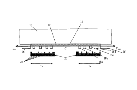
Figure 1 shows a structural member 10, in the form of a beam constituting part
of the
span of a bridge for example. An FRP laminate 12 in the form of a lamellar
strip, such as
a pre-cured CFRP laminate, has been applied to the structural member by
coating a
surface of the structural member 10 with a continuous or discontinuous layer
of curable
adhesive 14 and pressing the FRP laminate 12 against the adhesive-coated
surface. The
FRP laminate 12 is applied to the bottom surface of the structural member 10
so that its
fibres are parallel to the structural member's longitudinal axis.
A pre-stressing force, Pmax is then applied to each end of the FRP laminate 12
using a
pre-stressing device 16 comprising two lockable units located in the vicinity
of the ends of
the FRP laminate 12 and attached to the structural member 10 for example. The
exact
degree of pre-stressing may be measured with strain gauges positioned on the
FRP
laminate 12, or by means of an integral force measuring device housed in the
pre-
stressing device 16. Two series of stop blocks 18 are glued to the FRP
laminate 12 at a
pre-determined distance from the ends of the FRP laminate 12.
CA 02691497 2009-12-21
WO 2009/002268 PCT/SE2008/050792
The pre-stressing force, Pmax, is then decreased gradually in a continuous or
step-like
manner. While the pre-stressing force is being decreased, two moulds 20 that
comprise a
plurality of recesses 22 are fixedly arranged so as to prevent each stop block
18 from
being displaced beyond a predetermined distance in the direction opposite to
the direction
5 of application of the pre-stressing force, Pmax. Each recess 22 in the mould
20 is namely
arranged to receive one stop block 18. While the pre-stressing force is being
decreased,
the stop blocks 18 on the right-hand side of figure 1 are displaced to the
left towards the
centre C of the FRP laminate 12 and the stop blocks 18 on the left-hand side
of figure 1
are displaced to the right towards the centre C of the FRP laminate 12 until
the centre-
10 most side wall 24 of each recess 22 prevents further movement of a
corresponding stop
block 18 towards the centre C of the FRP laminate 12. A treatment length, LT,
at each end
of the FRP laminate 12 will therefore be less pre-stressed than the FRP
laminate 12
section at the centre C once the adhesive 14 has cured.
After curing of the adhesive 14, the pre-stressing device 16 is detached from
the structural
member 10 and the moulds 20 and the stop blocks 18 are preferably removed.
Using this
method a non-uniform axial force is created along the treatment length LT at
each end of
the FRP laminate 12, which decreases in the direction from the centre C of the
FRP
laminate to its ends, which causes a significant reduction in shear stress at
the very ends
of the FRP laminate 12.
A mould 20 that is suitable for use in the method illustrated in figure 1 is
shown in more
detail in figure 2A. The illustrated mould 20 comprises four recesses 22a-22d
of different
widths, D to D +3d, whereby the mould 20, when in use, is arranged so that the
width of
each recess 22a-22d increases in the direction of application of the pre-
stressing force.
The mould 20 may be placed at the right-hand end of the FRP laminate 12 in
figure 1,
when four stop blocks 18a-18d each having a width D have been glued to the FRP
laminate 12. The centre-most stop block 18a will be received in the centre-
most recess
22a which also has a width and will thus be prevented from moving any further
towards
the centre C of the FRP laminate 12. The second stop block 18b will be
prevented from
moving any further towards the centre C of the FRP laminate 12 once the end of
FRP
laminate 12 has moved a distanced towards the centre of the FRP laminate 12
etc. The
FRP laminate 12 will therefore be pre-stressed in a step-wise manner along the
treatment
length LT. It should be noted that the number, location and dimensions of the
recesses
22a-22d along the mould 20 and the number, location and dimensions of stop
blocks 18
CA 02691497 2009-12-21
WO 2009/002268 PCT/SE2008/050792
11
along the FRP laminate 12 will of course depend on the pre-stressing profile
that it is
desired to obtain along the FRP laminate 12, which in turn depends on the
particular
application.
Figure 2A shows a solid mould 20 that can be used for a specific type of
laminate when
applying a specific pre-stressing force. Alternatively a polylithic mould may
be used in a
method according to an embodiment of the invention . The mould 20 shown in
figure 2B
comprises movable blocks 18 that may be releasably, or non-releasably secured,
by
means of bolts 23 for example, at any position along the length of the mould
20. The
space 22 between the blocks 18 may therefore be adjusted depending on the type
of
laminate and the pre-stressing force being used in a particular application.
Figure 3 schematically shows an alternative method for applying an FRP
laminate 12 to a
structural member 10 which is similar to the method described in conjunction
with figures
1 and 2 but where the ends of the mould 20 (and not the ends of the FRP
laminate 12)
are clamped in a pre-stressing device 16 for example. The mould at the right-
hand side of
figure 3 is placed in the opposite direction to that shown in figure 2 whereas
the mould at
the left-hand side of figure 3 is placed as shown in figure 2. A pre-stressing
force, Pmax, is
applied to the mould 20, whereby the pre-stressed state of the mould 20 is
consequently
transferred to the FRP laminate 12. The pre-stressing force, Pmax, is then
decreased
gradually in a continuous or step-like manner. In this embodiment of the
invention, the
mould 20 therefore acts as both displacement-limiting means and as a means for
indirectly applying a pre-stressing force to the FRP laminate 12.
According to an alternative embodiment of the invention an FRP laminate 12 may
be
subjected to a non-uniform pre-stressing and adhered to the structural member
10 in a
non-uniformly pre-stressed state. A mould 20 may namely be used to apply an
increased
pre-stressing force to a length, Lc, of the FRP laminate 12 so that the FRP
laminate 12
along that length, Lc, will be more pre-stressed than the FRP laminate 12
along a length
section, LT, adjacent to that length Lc, when the adhesive 14 has cured.
Figure 4 shows a structural member 10 to which an FRP laminate 12 is being
applied
using a method according to a third embodiment of the invention. The method
comprises
the steps of subjecting a structural member 10 to non-uniform pre-stressing
along a
length, Lotal, and adhering the FRP laminate 12 to the structural member in a
non-
CA 02691497 2009-12-21
WO 2009/002268 PCT/SE2008/050792
12
stressed state. The non-uniform pre-stressing of the structural member 10 may
be carried
out by installing a plurality of pairs of mechanical posts 26 at predetermined
positions near
the surface of the structural member 10, whereby the two mechanical posts 26
of each
pair are located one at each end of the structural member 10, and
interconnecting the
mechanical posts 26 with a pre-stressing rod 28 or some other pre-stressing
means.
Grooves may for example be cut in the structural member the mechanical posts
26 may
be mechanically and/or adhesively fastened inside each groove.
The pre-stressing in this procedure is carried out in several steps. In the
first step, the
total pre-stressing force, Pmax) is applied to the structural member 10. Two
nuts of the two
inner mechanical posts 26a are tightened so that the pre-stressing rod 28
between the
two inner mechanical posts 26a is maintained at the total pre-stressing force,
Pmax. The
pre-stressing force is then reduced by a predetermined amount, such as by 20%,
and the
two nuts of the adjacent mechanical posts 26b are tightened so that the pre-
stressing rod
28 between those two mechanical posts 26b is maintained at that reduced pre-
stressing
force. This procedure is continued towards the ends of the structural member
10. Once
the procedure is completed, curable adhesive 14 is applied to the bottom
surface of the
structural member 10 and then an FRP laminate 12 is applied to that surface in
a non-
stressed state. Once the adhesive has cured, the pre-stressing force is
released by
opening the nuts of each pair of mechanical posts 26 starting with the
mechanical posts
26 located closest to the ends of the structural member 10 and working inwards
towards
the centre, C. The pre-stressing force is thus transferred from the structure
member 10 to
the FRP laminate 12. Even though the structural member 10 has to be modified
somewhat to install the mechanical posts 26, an advantage of this method is
that neither a
pre-stressing device nor a mould is required.
Figure 5 shows the axial force and shear stress versus the distance from the
end (0) of an
FRP laminate 12 towards its centre before treatment, i.e. when a pre-stressed
FRP
laminate is adhered to a non-pre-stressed structural member (see the
continuous lines in
figure 5),and after treatment, i.e. when a method according to an embodiment
of the
invention has been used to apply an FRP laminate to a structural member (see
the
dashed lines in figure 5). Using a method according to any of the embodiments
of the
invention reduces the slope of the axial force curve at the ends of the FRP
laminate along
the treatment length LT. Figure 5 shows that the treatment length, LT, is
divided into
several steps. The magnitude of the axial force is constant in each step. The
CA 02691497 2009-12-21
WO 2009/002268 PCT/SE2008/050792
13
accumulation of shear stress is thereby prevented by these constant force
intervals, i.e.
the steps break up the high shear stress curve and distribute it along the
treatment length,
LT, of the FRP laminate.
It should be noted that an FRP laminate 12 need not necessarily be applied in
a
substantially horizontal orientation to the underside of a structure, such as
a bridge, but
may be applied in any position or orientation on an interior surface (such as
the inside of a
pipe) or an exterior surface of a structure where reinforcement is required.
Furthermore,
an FRP laminate 12 need not be of uniform thickness as shown in the figures,
it need not
be applied to a planar surface, and it may be of any shape, length and size.
Further modifications of the invention within the scope of the claims would be
apparent to
a skilled person. For example it would be obvious for a skilled person that a
plurality of
FRP laminates having their fibres aligned in different directions could be
applied to a
structural member using a method according to an embodiment of the invention
in order
to provide the desired strengthening.