Note: Descriptions are shown in the official language in which they were submitted.
CA 02692061 2009-12-17
WO 2009/000428 1 PCT/EP2008/004720
THREADED ELEMENT OF A COMPONENT WITH OPPOSED THREADING
PORTIONS AND CORRESPONDING TUBULAR THREADF-n CONNECTION
The invention relates to threaded elements of components.
The term "component" as used here means any element or accessory intended to
be
connected by at least two threading portions to another component to
constitute with that other
component a made up connection such as a threaded tubular connection.
This invention relates to any type of component which may be subjected to
compressive
and/or tensile (or bending) loads once connected by making up onto another
corresponding
component, for example with the aim of constituting a threaded tubular
connection. Thus, it is
particularly suitable but not limited to oil applications and the like.
The component may, for example, be a tube (optionally a great length tube), a
tubular
coupling (optionally a few tens of centimeters long), an accessory for those
tubes (hanger, cross-
over, safety valve, a connector for a drilling pipe or tool joint, sub and the
like). Such
components may, for example, be used to drill or exploit a well. In this case,
the components are
connected together for dropping into a hydrocarbon or the like well and
constitute a drill string, a
casing string or liner string or also a tubing string (exploitation strings).
The threaded elements which make up the components of the type cited above
comprise a
threading comprising threads, for example with a generally trapezoidal form,
which each
comprise a rectilinear crest joining a stabbing flank and a loading flank and
which are separated
from each other by an axial distance (or hollow or thread root) sufficiently
large to house a
thread of a threading of a corresponding threaded element of another component
while leaving a
functional axial clearance for the corresponding threads.
Said axial clearance must be sufficient to allow easy engagement of the male
and female
threads (especiall_y when the loading flanks of the threads have a negative
angle (hook threads),
to allow them to be made up without axial interference and to avoid an
overpressure of grease
CA 02692061 2009-12-17
WO 2009/000428 2 PCT/EP2008/004720
during makeup by absorbing dimensional variations in the threads due to
machining tolerances
and to radial interference of the threads at the end of makeup.
Said axial clearance is not in itself a disadvantage for the tightness of
threaded
connections known as "premium" connections since the tightness therein is
ensured by
functional sealing surfaces independent of the threads.
In contrast, it tends to reduce the performance of threaded connections
subjected to axial
compressive loads.
After makeup, threaded connections with trapezoidal threads (and more
particularly
premium threaded connections which include specific sealing surfaces and axial
abutment
surfaces to position the sealing surfaces) are in contact via the loading
flanks, the axial clearance
being disposed between the stabbing flanks. When such threaded connections are
subjected to
axial tensile loads (for example because of the weight of the tubes below them
in the column),
the threads immediately transfer these loads via their loading flanks which
are already in contact.
In contrast, if they have to be subjected to axial compressive loads, the
threads cannot transfer
such loads via their stabbing flanks before taking up the axial clearance.
However, as the skilled person is aware, under certain situations the
components may at
certain times be subjected to axial tensile loads and compressive axial loads
at other times. This
is the case, for example, in certain wells when a component designed to
operate under tension is
subjected to compression due to a severe temperature variation (for example
when steam is
injected). This is also the case with components which are dropped into
deviated wells and/or
which undergo relatively severe variations in direction (doglegs) and which
are for this reason
subjected to bending loads which result in axial tensile stresses outside the
component and by
compressive stresses within it. As a result, in exploitation phases during
which said components
a.re subjected to compressive loads, certain portions of their threaded
elements, such as the
stabbing flanks of the threads, must take up their initial axial clearance
before being able to
contribute to supporting those loads (otherwise supported by axial abutments
if they exist), and
CA 02692061 2009-12-17
WO 2009/000428 3 PCT/EP2008/004720
the performances of the components under compression are reduced compared with
that with
tensile stresses.
As an example, European patent document EP 0 454 147 proposes using male and
female
threaded elements wherein the loading flanks and stabbing flanks of the
threads of one of the
threaded elements are, at the end of makeup, in contact with the loading
flanks and stabbing
flanks of the threads of the other threaded element, a radial clearance being
provided between the
thread roots and crests cooperating to limiting overpressure of grease. This
type of threading
allows the threaded connections to tolerate large loads both in tension and in
axial compression
(or bending). However, it is difficult to master on an industrial scale
because of the dimensional
tolerances of the widths of the threads and on the recesses between the
threads, the threadings
once made up possibly having either an axial clearance reducing their
compressive performance,
or having an axial interference fit occasioning poor positioning of the
sealing surfaces.
With the same aim of improving compressive properties, it has also been
proposed, for
example in patent documents US 6 155 613 and US 6 585 299, to use male and
female threaded
elements the respective threadings of which have only slightly different
pitches and very slightly
different axial widths, or wherein one of the threadings comprises a central
zone with a threading
pitch different from the neighbouring (periodic) threading pitches. The
disadvantage of those
solutions resides in the fact that they are difficult to control and operate.
Document US 4 629 222 uses threadings having, over the length of one of them,
a phase
change between the helices of the end thread portions, but essentially for
another aim, namely
that of increasing load transfer at the central threads.
The invention thus aims to improve the situation.
To this end, it provides a threaded element of a component comprising a free
end and at
least first aõd second threading portions each comprising threads each
comprising a stabbing
flank and a loading flank, the first threading portion being closest to the
free end; the second
threading portion being closest to a central non-threaded portion of the
component.
CA 02692061 2009-12-17
WO 2009/000428 4 PCT/EP2008/004720
It will be recalled that the stabbing flanks are those directed towards the
free end of the
component and which engage first during makeup, the loading flanks being
directed in the
direction opposite to the free end.
This threaded element is characterized in that the stabbing flanks and loading
flanks of
the threads of its first threading portion and the threads of the second
threading portion are
inclined in an "opposed" manner with respect to a radial direction.
In other words, the threads of the first and second threading portions of the
threaded
element have opposed inclinations, i.e. opposed with respect to the radial
direction, but not
necessarily of equal values.
By convention and in accordance with the usual practice, the flank angles will
be defined
in the present document as being negative when the end of the flank under
consideration at the
thread crest side overhangs the other end of the flank at the thread root, and
are positive when to
the opposite case (no overhang) applies.
A number of variations are possible with the threaded element of the
invention, wherein
at least some of the characteristics may be combined together, in particular:
= the angle of inclination (with respect to the radial direction) of the
stabbing flanks of the threads of the first threading portion of a male
threaded element or the second threading portion of a female threaded
element may be negative;
= the angle of inclination (with respect to the radial ~.irection) of the
loading
flanks of the threads of the first threading portion of a male threaded
element or the second threading portion of a female threaded element may
be positive;
= the absolute value of the angle of inclination (with respect to the radial
direction) of the stabbing flanks of the threads of the first threading
portion of a male threaded element or the second threading portion of a
CA 02692061 2009-12-17
WO 2009/000428 5 PCT/EP2008/004720
female threaded element may, for example, be lower than the absolute
value of the angle of inclination (with respect to the radial direction) of
the
loading flanks of the threads respectively of the f rst threading portion of a
male threaded element or the second threading portion of a female
threaded element;
^ as an example, the absolute value of the angle of inclination of the
stabbing flanks of the threads of the first threading portion of a male
threaded element or the second threading portion of a female threaded
element may be in the range from about 3 to about 15 ;
^ the absolute value of the angle of inclination of the stabbing flanks of
the threads of the first threading portion of a male threaded element or
the second threading portion of a female threaded element may be in
the range from about 10 to about 30 ;
= in a variation, the absolute value of the angle of inclination (with respect
to the radial direction) of the stabbing flanks of the threads of the second
threading portion of a male threaded element or of the first threading
portion of a female threaded element may, for example, be greater than the
absolute value of the angle of inclination (with respect to the radial
direction) of the loading flanks of the threads respectively of the second
threading portion of a male threaded element or the first threading portion
of a female threaded element;
^ as an example, the absolute value of the angle of inclination of the
loading flanks of the threads of the second threading portion of a male
threaded element or the first threading portion of a female threaded
element may be in the range from about 3 to about 15 ;
CA 02692061 2009-12-17
WO 2009/000428 6 PCT/EP2008/004720
^ as an example, the absolute value of the angle of inclination of the
stabbing flanks of the threads of the second threading portion of a
male threaded element or the first threading portion of a female
threaded element may be in the range from about 10 to about 30 ;
= the algebraic value of the angle of inclination of the stabbing flanks of
the
threads of the first threading portion may be su',,stantially equal to the
algebraic value of the angle of inclination of the loading flanks of the
threads of the second threading portion;
= the algebraic value of the angle of inclination of the loading flanks of the
threads of the first threading portion may be substantially equal to the
algebraic value of the angle of inclination of the stabbing flanks of the
threads of the second threading portion;
= the first and second threading portions may be tapered;
^ in this case, the second threading portion may, for example, be formed
after a radial shoulder of the desired radial extension;
^ in a variation, the first and second threading portions may, for
example, be disposed substantially on the same tapered surface;
= in a variation, the first and second threading portions may be straight and
formed at first and second radial distances from the longitudinal axis of
said component;
= the first and second threading portions may be axially separated by an
intermediate zone which extends over an axial distance selected so as to
absorb external loads and/or to take up an axial clearance between the first
or second threading portion of a threaded element and respectively the
second or first portion of the threading of a matching threaded element, by
essentially elastic deformation;
CA 02692061 2009-12-17
WO 2009/000428 7 PCT/EP2008/004720
^ the axial extent of the intermediate zone may be proportional to the
maximum value of the axial clearance;
^ the minimum value of the axial clearance may be an increasing
function of the thread height and the absolute value of the negative
angle of the flank;
^ at least a portion of the intermediate zone may define a sealing surface
which can come into tight interference contact with a corresponding
sealing surface of another threaded element.
The invention also proposes a threaded tubular connection comprising a male
threaded
element and a female threaded element which are of the type described above,
and which
correspond, to be able to be made up one into the other.
As an example, the first and second threading portions may be disposed so
that, once
made up and in the absence of external tensile, compressive or bending loads,
on the one hand
the stabbing flanks of the threads of the first threading portion of the
female threaded element be
in contact with those of the second threading portion of the male threaded
element corresponding
thereto, and on the other hand the loading flanks of the threads of the second
threading portion of
the female threaded element be in contact with those of the first threading
portion of the male
threaded element which correspond thereto, providing on the one hand a first
buffer zone
between the loading flanks of the threads which correspond thereto in the
first threading portion
of the female threaded element and in the second threading portion of the male
threaded element,
and on the other hand a second buffer zone between the stabbing flanks of the
threads which
correspond thereto in the second threading portion of the female threaded
element and in the first
threading portion of the male threaded element. The first buffer zones are
thus intended to take
up an axial clearance in the presence of a tensile load and the second buffer
zones are intended to
take up an axial clearance in the presence of a compressive load.
CA 02692061 2009-12-17
WO 2009/000428 8 PCT/EP2008/004720
Other characteristics and advantages of the invention will become apparent
from the
following detailed description and the accompanying drawings, in which:
= Figure 1 diagrammatically shows, in a cross section along the longitudinal
axis XX, an example of an embodiment of a female threaded element of a
first component of a threaded tubular connection of the "flush" type;
= Figure 2 diagrammatically shows, in a cross section along the longitudinal
axis XX, an example of an embodiment of a male threaded element of a
second component of a flush type threaded tubular connection;
= Figure 3 diagrammatically shows, in a cross section along the longitudinal
axis XX, an example of an embodiment of a threaded tubular connection
constituted by a connection formed by male and female threaded elements
of the type shown in Figures 1 and 2;
= Figure 4 diagrammatically shows, in a cross section along the longitudinal
axis XX, an example of an embodiment of the threads of a first threading
portion of a male threaded element of the type shown in Figure 2;
= Figure 5 diagrammatically shows, in a cross section along the longitudinal
axis XX, an example of an embodiment of the threads of a second
threading portion of a male threaded element of the type shown in Figure
2;
= Figure 6A diagrammatically shows, in a cross section along the
longitudinal axis XX, an example of the cooperation of the threads of a
second threading portion of a male threaded element of the type shown in
Figure 2 and the threads of a first threading portion of a female threaded
element of the type shown in Figure 1, at the end of the makeup cycle in
the absence of external loads;
CA 02692061 2009-12-17
WO 2009/000428 9 PCT/EP2008/004720
= Figure 6B diagrammatically shows, in a cross section along the
longitudinal axis XX, an example of the cooperation of the threads of a
first threading portion of a male threaded element of the type shown in
Figure 2 and the threads of a second threading portion of a female
threaded element of the type shown in Figure 1, at the end of the makeup
cycle and in the absence of external loads;
= Figure 7A diagrammatically shows, in a cross section along the
longitudinal axis XX, an example of the cooperation of the threads of a
second threading portion of a male threaded element of the type shown in
Figure 2 and the threads of a first threading portion of a female threaded
element of the type shown in Figure 1, at the end of the makeup cycle and
in the presence of axial tensile loads;
= Figure 7B diagrammatically shows, in a cross section along the
longitudinal axis XX, an example of the cooperation of the threads of a
first threading portion of a male threaded element of the type shown in
Figure 2 and the threads of a second threading portion of a female
threaded element of the type shown in Figure 1, at the end of the makeup
cycle and in the presence of axial tensile loads;
= Figure 8A diagrammatically shows, in a cross section along the
longitudinal axis XX, an example of the cooperation of the threads of a
second threading portion of a male threaded element of the type shown in
Figure 2 and the threads of a first threading portion of a female threaded
element of the type shown in Figure 1, at the end of the makeup cycle and
in the presence of axial compressive loads; and
= Figure 8B diagrammatically shows, in a cross section along the
longitudinal axis XX, an example of the cooperation of the threads of a
CA 02692061 2009-12-17
WO 2009/000428 10 PCT/EP2008/004720
first threading portion of a male threaded element of the type shown in
Figure 2 and the threads of a second threading portion of a female
threaded element of the type shown in Figure 1, at the end of the makeup
cycle and in the presence of axial compressive loads.
The accompanying drawings will not only serve to explain the invention, but
also to
contribute to its definition as appropriate.
The invention aims to provide male and female threaded elPments of components,
possibly threaded tubular connections, capable of tolerating, in a controlled
manner, high levels
of compressive as well as tensile loads, or high levels of bending loads, or
even these loads in
alternation.
In the following, it is assumed that the component is intended for drilling or
exploitation
of hydrocarbon wells and that it is provided with at least one male or female
threaded element of
a coupled or integral threaded tubular connection. The invention concerns any
type of
component (OCTG casing, liner or tubing, coupling, drill string, drilling
accessory or well
accessory, and the like), regardless of its use, provided that it includes at
least one male or
female threaded element provided with at least two threading portions which
can be made up
onto two threading portions of a male or female threaded element ot another
component to
constitute a made up assembly with this other component, a non-limiting
example being a
threaded tubular connection. In general, the invention concerns any type of
component which
can undergo external compressive and/or tensile or bending loads once
connected by making up
onto another corresponding component.
As can be seen in Figures 1 and 2, a component Ti (i = 1 or 2) comprises a
body or
regular or central portion PCi prolonged by a female threaded element (or end)
EF or male
threaded element EM terminated by a free end ELi.
CA 02692061 2009-12-17
WO 2009/000428 11 PCT/EP2008/004720
The free end ELi of the female threaded element EF or male EM serves here as a
reference. As a result, all that which lies, with respect to a given
transverse plane, between said
plane and a free end ELi is said to be upstream of that plane.
A female threaded element EF of the invention (see Figure 1) comprises at
least first FI1
and second F12 distinct portions of the interior threading.
The term "interior" as used here means a portion disposed on a surface (or a
surface)
which is orientated towards the longitudinal axis XX of the female threaded
element EF or male
threaded element EM. The radial direction is that which is perpendicular to
the longitudinal axis
XX.
Further, the term "threading portion" as used here means a zone in which
threads TH 1 or
TH2 are formed each defined by a stabbing flank FS and a loading flank FL (see
Figures 4 and
5). According to the definition given above, the stabbing flank of a thread TH
1 or TH2 is
normally placed upstream of the loading flank FL of the same thread TH 1 or
TH2. The thread
pitch is generally constant for a given threading portion. Further, the radial
height of the threads
is also generally constant, but it could be increasing or decreasing (as is
the case with run-in or
run-out threadings).
The first interior threading portion FI1 is that which is placed closest to
the free end ELI
of the first component T1. The second interior threading portion F12 is that
which is placed
closest to the non-threaded portion (and thus the body PC 1) of the first
component T 1.
In the example shown in Figure 1, the interior threading portion FIl is placed
downstream of the free end EL1, the second interior threading portion F12 is
placed downstream
of the interior threading portion FI1, which may be placed upstream of a
makeup abutment BVF
(as shown). This makeup abutment BVF is, for example, in the form of an
internal surface
which is of the reverse tapered annular type.
CA 02692061 2009-12-17
WO 2009/000428 12 PCT/EP2008/004720
As shown in Figure 1, the female threaded element EF may also and optionally
comprise
a metal/metal sealing surface SEF interposed between the second interior
threading portion F12
and the makeup abutment BVF.
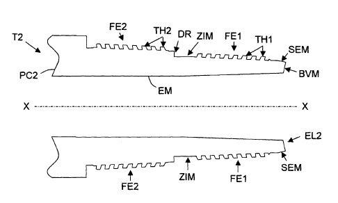
A male threaded element EM of the invention (see Figure 2) comprises at least
one first
FE 1 and second FE2 exterior threading portions.
The term "exterior" as used here means an element disposed along a surface (or
a
surface) which is orientated in a direction radially opposite to the
longitudinal axis XX of the
male EM or female EF threaded element.
The exterior first threading portion FE 1 is that which is placed closest to
the free end EL2
of the second component T2. The second exterior threading portion FE2 is that
which is placed
closest to the regular portion or central portion (and thus the body PC2) of
the second component
T2.
In the example shown in Figure 2, the first exterior threading portion FE 1 is
placed
downstream of the free end EL2, the second exterior threading portion FE2 is
placed
downstream of the first exterior threading portion FE1, which is placed
upstream of a makeup
abutment BVM (as shown). This makeup abutment BVM is, for example, in the form
of a
reverse tapered annular end surface placed upstream of the first exterior
threading portion FEI at
the free end EL2. It is intended to bear on the corresponding makeup abutment
BVF of the
female threaded element EF at the end of the makeup cycle (see Figure 3).
As shown in Figure 2, the male threading element EM may also and optionally
comprise
a metal/metal SEM sealing surface interposed between the first exterior
threading portion FEI
and the makeup abutment BVM. This metal/metal sealing surface SEM is intended
to bear on
the corresponding metal/metal sealing surface SEF of the female threaded
element EF at the end
of the makeup so as to establish a tight interference fit.
CA 02692061 2009-12-17
WO 2009/000428 13 PCT/EP2008/004720
It should be noted that the interior threading portions FI1 and F12, like the
exterior
threading portions FE1 and FE2, may be disposed on straight or tapered
surfaces, provided that
they allow access to the threads TH2 of the second interior threading F12 or
exterior FE2 portion.
As a result, a number of configurations may be envisaged. Thus, when the first
FI1 or
FE 1 and second FE2 or FE2 threading portions are tapered, the second
threading portion F12 or
FE2 may, for example (and as shown in Figures 1 and 2) be formed downstream of
a radial
shoulder DR of the desired radial extension. Further and as shown in Figures 1
and 2, the second
threading portion F12 or FE2 is preferably separated from the first threading
portion Fll or FE1
by an intermediate non-threaded zone ZIF or ZIM and desired axial extension.
This intermediate zone ZIF or ZIM is intended to facilitate access to threads
TH2 of the
second interior F12 or exterior FE2 threading portion and to reduce or cancel
the effect of an
axial threading clearance which is necessary for making up the opposed
threaded portions.
In a variation, not shown, the first Fll or FE1 and second F12 or FE2
threading portions
may, for example, constitute two portions of the same tapered threading. In
this case, it is
preferable that the first Fll or FE1 and second F12 or FE2 threading portions
are axially
separated by an intermediate non-threaded zone which may be tapered (but
possibly straight) and
with a desired axial extension, intended to facilitate access to threads TH2
of the interior second
F12 or exterior FE2 threading portion and to reduce or cancel the effect of an
axial threading
clearance which is necessary to making up the opposed threaded portions.
In another variation, not shown, the first FI l or FE 1 and second F12 or FE2
threading
portions may, for example, be straight. In this case, they must obligatorily
be formed at first and
second radial distances from the longitudinal axis XX. In the case of a female
threaded element
EF, the first radial distance which separates the longitudinal axis XX from
the first interior
threading portion FIl must be greater than the second radial distance which
separates the
longitudinal axis XX from the second interior threading portion F12. = In the
case of a male
threaded element EM, the radial first distance which separates the
longitudinal axis XX from the
CA 02692061 2009-12-17
WO 2009/000428 14 PCT/EP2008/004720
first exterior threading portion FE 1 must be lower than the second radial
distance which
separates the longitudinal distance XX from the second exterior threading
portion FE2.
As can be seen in Figure 3, a threaded tubular connection is constituted by
making up a
female threaded element EF of a first component T1 (of the type shown in
Figure 1) onto a male
threaded element EM of a second component T2 (of the type shown in Figure 2).
In accordance with the invention, in each female EF or male EM threaded
element the
stabbing flanks FS and the loading flanks FL of the threads TH 1 of the first
threaded portion FI1
or FE 1 of the threads TH2 of the second threading portion F12 or FE2 are
inclined in an
antagonistic manner (i.e. opposing) with respect to the radial direction. This
configuration is
shown in Figures 4 and 5 in the case of a male threaded element EM of the type
shown in Figure
2. More precisely, in the non-limiting example shown in Figures 2, 4 and 5,
the stabbing flanks
FS and the loading flanks FL of the threads TH1 of the first exterior
threading portion FE1 are
inclined (or orientated) towards the free end EL2 of the second component T2
so that the end of
the stabbing flank FS and the end of the loading flank FL on the thread crest
side respectively
overhangs and does not overhang the other end of these flanks at the thread
root, while the
stabbing flanks FS and the loading flanks FL of the threads TH2 of the second
exterior threading
portion FE2 are inclined (or orientated) towards the non-threaded portion (or
body) CP2 of the
same second component T2, so that the end of the stabbing flank FS and the end
of the loading
flank FL on the thread crest side respectively doe not overhang and overhangs
the other end of
these flanks at the thread root. Similarly, in the non-limiting example shown
in Figure 1, the
stabbing flanks FS and loading flanks FL of the threads TH 1 of the first
interior threading
portion FI1 are inclined (or orientated) towards the non-threaded portion (or
body) CP 1 of the
first component T1 so that the end of the stabbing flank FS and the end of the
loading flank FL
on the thread crest side respectively does not overhang and overhangs the
other end of these
flanks at the thread root, while the stabbing flanks FS and the loading flanks
FL of the threads
TH2 of the second exterior threading portion FE2 are inclined (or orientated)
towards the free
CA 02692061 2009-12-17
WO 2009/000428 15 PCT/EP2008/004720
end EL1 of that same first component T1 so that the end of the stabbing flank
FS and the end of
the loading flank FL on the thread crest side respectively overhangs and does
not overhang the
other end of said flanks at the thread root.
The angle of inclination between a loading flank FL of a thread THI of the
first exterior
threading portion FE1 and the radial direction is denoted (DL1. The angle of
inclination between
a stabbing flank FS of a thread TH 1 of the first exterior threading portion
FE 1 and the radial
direction is denoted (Dsl. The angle of inclination between a loading flank FL
of a thread TH2 of
the second exterior threading portion FE2 and the radial direction is denoted
(DL2. The angle of
inclination between a stabbing flank FS of a thread TH2 of the second exterior
threading portion
FE2 and the radial direction is denoted (DS2.
If, for example, we assume that the angles of inclination are positive when
the end of the
flank concerned on the thread crest side does not overhang the other end of
that flank at the
thread root, and negative when the end of the flank concerned on the thread
crest side overhangs
the other end of that flank at the thread root, then in the example shown, the
angles (DL, and (Dsl
are respectively positive and negative, while the angles (DL2 and (DS2 are
respectively negative
and positive in the case of the male threaded element EM. The converse is
observable on the
example of a female threaded element EF in Figure 1. In this case, the angles
(DL, and (Dsl of the
flanks FL and FS of threads THI of the first interior threading portion fl l
are respectively
negative and positive, while the angles (DL2 and (DS2 of the flanks FL and FS
of threads TH2 of
the second interior threading portion F12 are respectively positive and
negative.
It should be noted that the reverse situation may be envisaged. In this case,
angles (DL1
and (Ds, of flanks FL and FS of threads THI of the first interior threading
portion FI1 are
respectively positive and negative, the angles (DL2 and (DS2 of flanks FL and
FS of threads TH2 of
the second interior threading portion F12 are respectively negative and
positive, the angles (DLi
and (Ds 1 of flanks FL and FS of threads TH 1 of the first exterior threading
portion FE 1 are
CA 02692061 2009-12-17
WO 2009/000428 16 PCT/EP2008/004720
respectively negative and positive, and the angles (DL2 and (Ds2 of flanks FL
and FS of threads
TH2 of the second exterior threading portion FE2 are respectively positive and
negative.
It should also be noted that angles (DL1 and (Dsl of flanks FL and FS of
threads THI of the
first exterior threading portion FE1 or interior threading portion FI1 may be
identical or different
(as is the case in the example shown in Figures 1, 2 and 4). Preferably, the
absolute value of the
angle of inclination (Dsl of the stabbing flank FS of threads THI of the first
exterior threading
portion FE1 is lower than the absolute value of the angle of inclination (DLi
of the loading flanks
FL of threads THI of that same first exterior threading portion FE1. As an
example, the absolute
value of the angle of inclination (Ds, of stabbing flanks FS of threads TH1 of
the first exterior
threading portion FE1 may be in the range from about 3 to about 15 . As an
example, (Dsl may
be selected as being equal to -10 . The absolute value of the angle of
inclination (DL1 of the
loading flanks FL of the threads TH1 of the first exterior threading portion
FEI may, for
example, be in the range from about 10 to about 30 . As an example, cDLl may
be selected to be
equal to +25 .
Preferably again, the absolute value of the angle of inclination cDS2 of the
stabbing flanks
FS of threads TH2 of the second exterior threading portion FE2 is higher than
the absolute value
of the angle of inclination (DL2 of the loading flanks FL of threads TH2 of
that same second
exterior threading portion FE2. As an example, the absolute value of the angle
of inclination (Dsz
of the stabbing flanks FS of threads TH2 of the second exterior threading
portion FE2 may be in
the range from about 10 to about 30 . As an example, (DS2 may be selected as
being equal to
+25 . The absolute value of the angle of inclination (DL2 of the loading
flanks FL of the threads
TH2 of the second exterior threading portion FE2 may, for example, be in the
range from about
3 to about 15 . As an example, (DL2 may be selected to be equal to -10 .
Similarly, the absolute value of the angle of inclination (Dsl of the stabbing
flanks FS of
threads TH1 of the first interior threading portion FI1 is preferably higher
than the absolute value
CA 02692061 2009-12-17
WO 2009/000428 17 PCT/EP2008/004720
of the angle of inclination (DL1 of the loading flanks FL of threads TH1 of
that same first interior
threading portion FIl. As an example, the absolute value of the angle of
inclination (Dsl of the
stabbing flanks FS of threads TH1 of the first interior threading portion FI1
may be in the range
from about 10 to about 30 . As an example, (Dsl may be selected as being
equal to +25 . The
absolute value of the angle of inclination (DLt of the loading flanks FL of
the threads TH1 of the
first interior threading portion FIl may, for example, be in the range from
about 3 to about 15 .
As an example, 0i,l may be selected to be equal to -10 .
Preferably again, the absolute value of the angle of inclination (DS2 of the
stabbing flanks
FS of threads TH2 of the second interior threading portion F12 is lower than
the absolute value of
the angle of inclination (DL2 of the loading flanks FL of threads TH2 of that
same second interior
threading portion F12. As an example, the absolute value of the angle of
inclination (DS2 of the
stabbing flanks FS of threads TH2 of the second interior threading portion F12
may be in the
range from about 3 to about 15 . As an example, (DS2 may be selected as being
equal to -10 .
The absolute value of the angle of inclination (DLl of the loading flanks FL
of the threads TH2 of
the second interior threading portion F12 may, for example, be in the range
from about 10 to
about 30 . As an example, (DL2 may be selected to be equal to +25 .
Preferably, regardless of the thread flank and the threading portion, the
absolute value of
the negative angles is less than that of the positive angles. Thus in the non-
limiting example of
Figure 3, the absolute value of the angle (Dsl (10 ) is less than that of the
angle (DL, (25 ).
It should also be noted that preferably, the angle of inclination (Ds, of the
stabbing flanks
FS of the threads THI of the first interior threading portion FI1 is
substantially equal to the angle
of inclination (Ds2 of the stabbing flanks FS of the threads TH2 of the second
exterior threading
portion FE2. Similarly, the angle of inclination (DL1 of the loading flanks FL
of the threads TH1
of the first interior threading portion FIl is preferably substantially equal
to the angle of
CA 02692061 2009-12-17
WO 2009/000428 18 PCT/EP2008/004720
inclination 0L2 of the loading flanks FL of the threads TH2 of the s::cond
exterior threading
portion FE2.
It should also be noted that the axial length of the first interior threading
portion FI1 (or
exterior FE1) of a female threaded element EF (or male EM) is preferably equal
to that of the
second interior threading portion F12 (or exterior FE2) of the same female
threaded element EF
(or male EM). However, the axial length of the threading portions may be
selected as a function
of other criteria, for example, and in a non-limiting manner, to equilibrate
the developed surfaces
of the loading flanks FL or the stabbing flanks FS of the first and second
threading portions of
the same threading.
Figures 6A and 6B show in diagrammatic manner (in cross section along the
longitudinal
axis XX) the respective positions of threads TH2 of a second exterior
threading portion FE2 of a
male threaded element EM and threads TH1 of a first interior threading portion
FIl of a female
threaded element EF, at the end of a makeup cycle for first T1 and second T2
components and in
the absence of external loads. As can be seen in Figures 6A and 6B, the
respective arrangements
of the first threading portions FI1 and FE1 and the second threading portions
F12 and FE2 enable
to define:
= a first buffer zone ZTI between the loading flanks FL of threads THI and TH2
which respectively correspond in the first interior threading portion FI1 (of
the
female threaded element EF) and in the second exterior threading portion FE2
(of
the male threaded element EM); and
= a second buffer zone ZT2 between the stabbing flanks FS of threads TH2 and
TH 1 which respectively correspond in the second interior threading portion
F12
(of the female threaded element EF) and in the first exterior threading
portion FE 1
(of the male threaded element EM).
In the absence of external load, the antagonistic (opposed) inclinations of
the threads of
the first FI1 and second F12 interior threading portions of the female
threaded element EF,
CA 02692061 2009-12-17
WO 2009/000428 19 PCT/EP2008/004720
combined with the antagonistic (opposed) inclinations of the threads of the
first FE 1 and second
FE2 exterior threading portions of the male threaded element EM ensures that
the stabbing
flanks FS of the threads TH 1 and TH2, respectively of the first interior
threading portion FI 1 and
the second exterior threading portion FE2, bear on each other, and at titt
same time the loading
flanks FL, of threads TH2 and TH1, respectively of the second interior
threading portion FI2 and
the first exterior threading portion FE1, bear on each other. This results in
a wedging effect
which ensures radial locking of the first T 1 and second T2 components, which
substantially
improves the overall integrality of their connection.
As can be seen in Figures 7A and 7B, the axial clearance of the first buffer
zones ZT1 is
intended to be taken up during axial tensile load, while as shown in Figures
8A and 8B, the axial
clearance of the second buffer zones ZT2 is intended to be taken up during
axial compressive
load. It will thus be understood that in the presence of axial compressive and
tensile loads (for
example on opposite generatrices during bending), the first ZT1 and second ZT2
buffer zones are
used on the same connection to take up the axial clearances. This latter
situation corresponds in
some way to a combination of Figures 7A, 7B on one generatrix and 8A, 8B on
the opposite
generatrix.
The axial extensions (axial clearances) of the first ZT 1 and second ZT2
buffer zones
shown in Figures 6 to 8 have been deliberately exaggerated to make them easier
to understand.
In other words, the axial clearances which they can take up are exaggerated
compared with the
actual situation.
The intermediate zone ZIF or ZIM, which is located between the first FI 1 or
FE 1 and
second F12 or FE2 threading portions, is also useful in the presence of axial
compressive and/or
tensile loads. In the presence of axial tensile loads (see Figures 7A and 7B),
once the axial
clearances of the first buffer zones ZTl have been taken up, the tensile loads
are taken up by all
of the loading flanks FL of the first interior threading portions FI1 and
exterior threading
portions FE 1 and second interior threading portions F12 and exterior
threading portions FE2.
CA 02692061 2009-12-17
WO 2009/000428 20 PCT/EP2008/004720
More precisely, once the axial clearances have been taken up, the traction
induces a
supplemental contact between the loading flanks FL of the first interior
threading portion FI1
and the second exterior threading portion FE2, which supplemental contact can
take up part of
the load and thus relieve the loads to which the second interior threading
portion FI1 and first
exterior threading portion FE2 are subjected. The intermediate zone ZIM will
then guarantee
this clearance take up by elastic deformation (and thus without notable
Yermanent alteration) in
axial tension, thereby allowing the coupling (in this case a threaded tubular
connection) to return
to a condition identical to or close to its initial condition when the load is
released.
The action of the intermediate zone ZIF in the presence of axial compressive
loads (see
Figures 8A and 8B) is similar to that described above for the intermediate
zone ZIM in the case
of tensile loads. The difference lies in the fact that the loads are taken up
by all of the stabbing
flanks FS of the first interior threading portions FIl and exterior threading
portions FE1 and
second interior F12 and exterior FE2 threading portions and in that the
intermediate zone ZIF
will enable to ensure that the clearance is taken up by elastic deformation in
axial compression.
The axial extent of the minimum cross section portion of the intermediate
zones ZIM,
ZIF is preferably selected so as not to be plasticized before take up of the
axial clearance of the
corresponding buffer zones, respectively ZT1, ZT2.
Highly preferably, the axial extent of the minimum cross section portion of
the
intermediate zones ZIM, ZIF is an increasing linear function of the maximum
axial extent of the
corresponding buffer zones ZT1, ZT2. The maximum axial extent of these buffer
zones is equal
to the maximum axial clearance between the threading portions FE2-FIl or FE 1-
FI2 depending
on the case, taking into account the dimensional tolerances on the threadings.
Thus, by way of example, for elastic limits of the order of 700 MPa (grade C95
of
specification API 5CT), the axial extent or length of the minimum cross
section portion of the
intermediate zones ZIM, ZIF may be equal to about 200 times the maximum axial
clearance of
CA 02692061 2009-12-17
WO 2009/000428 21 PCT/EP2008/004720
the threadings if plastic deformation of the intermediate zone is effectively
not tolerated. It may
be about 100 times the axial clearance if a small amount of plastic
deformation is tolerated.
The maximum axial extent of the buffer zones ZT1, ZT2 may be equal to the
minimum
axial clearance between the threading portions FE2-FI1 or FE 1-FI2 depending
on the case,
supplemented by the dimensional machining tolerance of the axial clearances.
The minimum axial extent of the buffer zones ZT1, ZT2 (which is equal to the
minimum
axial clearance between the threading portions FE2-FI1 or FE 1-FI2 depending
on the case) is
preferably selected to avoid premature galling due to the negative flank
angles. In this case, it is
preferably an increasing function of the threading height and the absola~e
value of the negative
flank angle. More preferably, it may be equal to h.tan((DL2); (DL2 being the
loading flank angle of
the second exterior threading portion FE2.
It should be noted that the intermediate zones ZIM and ZIF may also define (at
least
partially) metal/metal sealing surfaces if products are required having
reduced radial bulk. This
is particularly the case with components of threaded connections known as
"integral semi-flush"
connections which may thus comprise a first metal/metal sealing surface
between their first FI1
or FE1 and second F12 or FE2 threading portions and a second metal/metal
sealing surface either
downstream of their second interior threading portion F12 in the case of a
female threaded
element EF or upstream of their first exterior threading portion FE 1 in the
case of a male
threaded element EM.
The invention is not limited to the embodiments of the threaded element (male
or
female), the component and the threaded tubular connection described above
solely by way of
example, but they encompass all variations which the skilled person may
envisage in the context
of the claims below.
Thus, the invention also concerns other types of male and female threaded
element than
those described above. As an example, it also concerns threaded elements of
threaded tubular
connections with internal abutments, coupled (for example those of the VAM
TOP, NEW VAM,
CA 02692061 2009-12-17
WO 2009/000428 22 PCT/EP2008/004720
VAM ACE, DINOVAM, VAM HW ST type) or integral "flush" or "semi-flush" (for
example
those of the VAM SL, VAM MUST, VAM HP type). The invention also concerns male
and
female threaded elements of connections with no internal abutment (for example
of the VAM
SLIJ II type with a central abutment or VAM FJL with an external abutment).