Note: Descriptions are shown in the official language in which they were submitted.
CA 02692105 2010-02-04
Ground Connector
BACKGROUND OF THE INVENTION
Field of the Invention
[0001] The invention
relates to a raised floor system
and, more particularly, to grounding in a raised floor
system.
Brief Description of Prior Developments
[0002] It is known
in raised floor structures, used in
a building having numerous computer or telephone or
electrical devices, to provide a grounding network. The
understructure of a raised floor system includes multiple
pedestals and perhaps stringers and seismic supports.
Floor panels are located on top of the pedestals. The
panels can include, for example, aluminum panels, or
steel panels such as hollow, perforated, grated, concrete
filled, wood filled and calcium chloride filled.
[0003] A grounding
network of a raised floor system
can comprise ground conductors or cables arranged in a
parallel grid or a perpendicular grid. A ground
connector is used to connect the cable to the pedestal of
the raised floor system. U.S. Patent
No. 5,286,211
discloses a ground connector where conductors can be
clamped directly against a post in two orthogonal
orientations. There is a desire for a faster and less
expensive way to connect a ground conductor to a pedestal
of a raised floor system.
1
CA 02692105 2010-02-01mk
411
SUMMARY
[0004] The following
summary is merely intended to be
exemplary. The summary is not intended to limit the
scope of the claimed invention.
(0005] In accordance
with one aspect of the invention,
a ground connector is provide comprising a first section
and a second section. The first
section comprises a
first member with a threaded post, a second member
pivotably connected to the first member, and a worm drive
on the first member. The second member comprises teeth
configured to be engaged by the worm drive to clamp a
pedestal directly between the first and second members.
The second section is movably located on the threaded
post and configured to directly contact and clamp a
conductor towards the pedestal.
[0006] In accordance with another aspect of the
invention, a ground connector is provided including a
first section and a second section. The first section
includes a first member with a threaded post, and a
system including a screw configured to clamp the first
section against opposite sides of a support. The second
section is movably located on the threaded post and
configured to directly contact and clamp a conductor
towards the support.
[0007] In accordance with another aspect of the
invention, a method is provide comprising connecting a
first section of a ground connector to a pedestal,
wherein the first section comprises a first member with a
threaded post, a second member pivotably connected to the
first member, and a worm drive on the first member,
wherein the second member comprises teeth engaged by the
2
CA 02692105 2010-02-03 411
worm drive to clamp a pedestal directly between the first
and second members; and positioning a second section on
the threaded post to directly contact and clamp a
conductor towards the pedestal.
BRIEF DESCRIPTION OF THE DRAWINGS
[0008] The foregoing aspects and other features of the
invention are explained in the following description,
taken in connection with the accompanying drawings,
wherein:
[0009] Fig. 1 is a perspective view of a raised floor
system comprising features of the invention;
[0010] Fig. 2 is a perspective view of an electrical
connector attached to one of the pedestals;
[0011] Fig. 3 is a perspective view of the electrical
connector shown in Fig.2;
[0012] Fig. 4 is a perspective view of one of the
members of the connector shown in Figs. 2-3;
[0013] Fig. 5 is a perspective view of another one of
the members of the connector shown in Figs. 2-3; and
[0014] Figs. 6-9 are perspective views an alternate
embodiment of one of the sections of the connector shown
in Figs. 2-3.
DETAILED DESCRIPTION OF EMBODIMENTS
[0015] Referring to Fig. 1, there is shown a view of a
raised floor system 10 incorporating features of the
invention. Although the invention will be described with
3
CA 02692105 2010-02-04
111
reference to the example embodiments shown in the
drawings, it should be understood that the invention can
be embodied in many alternate forms of embodiments. In
addition, any suitable size, shape or type of elements or
materials could be used.
(0016] The system 10
generally comprises pedestals 12
and panels 14. The panels 14 are conventional panels of
a raised floor system. Each pedestal
12 generally
comprises a first section 16 and a second section 18.
The second section 18 is adjustably connected to the
first section 16 in this embodiment. However, in
alternate embodiments the second section might not be
movably connected to the first section. The first
section 16 comprises a base 20 and a post 22. The base
and post are preferably comprised of metal. In this
embodiment the post 22 is stationarily attached to the
base, such as by welding. However,. in
alternate
embodiments the base and post could be integrally formed
or connected in any other suitable method.
0017] The base 20
is sized and shaped to sit or rest
on a floor, such as a concrete floor of an office
building for example. The base 20 has a general square
or rectangular planar shape, but could have other shapes.
In an alternate embodiment the base could be sized and
shaped to connect to another member.
0018] The post 22
extends upward from the base 20.
The post 22 has a general tube shape. In the embodiment
shown the tube shape is generally circular in cross
section, but could have alternative cross sectional
shapes. An aperture extends into the top end of the post
22 into the central channel of the tube shape.
4
CA 02692105 2010-02-03
411
[0019] The second
section 18 generally comprises a
post 26 and a top support 28. The post 26
and top
support 28 are conventional in this embodiment. The post
26 is a threaded post with threads on its exterior side.
The top support 28 is connected to the top end of the
post 26. The top side of the top support 28 is adapted
to support the panels 14 thereon.
[0020] The second
section 18 comprises an adjuster,
such as a nut. The adjuster is connected to the threads
of the post 26. The bottom side of the nut rests on the
top end of the post 22. In alternate embodiments any
suitable type of height adjustment system between the
first and second sections could be provided.
[0021] The bottom
end of the post 26 extends into the
center channel of the post 22 through the open top end of
the post 22. With the nut resting on the top support
surface of the post 22, when the nut is turned the post
26 can move up and down relative to the post 22. Thus,
the height of the top support 28 relative to the base 20
can be adjusted.
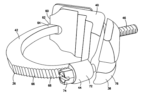
[0022] Referring also to Fig. 2, the system 10
includes a grounding system which is used to ground the
raised floor system to ground. The grounding system
includes electrical conductors 30, 32 and electrical
ground connectors 34. Referring
also to Fig. 3, the
connector 34 generally comprises a first section 36 and a
second section 38. The first
section 36 generally
comprises a first member 40, a second member 42 and a
worm drive 44.
[0023] Referring
also to Fig. 4, the first member 40
is a one-piece substantially rigid metal member. The
= 411 CA 02692105 2010-02-03.
first member 40 has a general V shaped member 48 and a
threaded post 46. The member 48 has two sections 50, 52
which are generally orthogonal to each other. Exterior
facing sides of the sections 50, 52 each have two
conductor receiving grooves 54, 56 therealong. In this
embodiment the grooves have different sizes, but they
could have the same size. The opposite facing side 58 is
configured to be located directly against the exterior
surface of the post 22.
(0024] The second member 42 is pivotably connected to
a first end 60 of the first member 40 at pivot connection
62. The second member 42 is a one-piece substantially
rigid metal member having a general curved shape.
However, the member 42 might not be rigid. A first end
64 is pivotably connected at the pivot connection 62. A
side of the second member 42 has teeth 66 which extend to
a second end 68 of the second member 42.
(0025] The worm drive 44 is located at the second end
70 of the first member 40. The worm drive 44 has a
housing 72 formed by part of the first member 40 and a
worm screw 74 in the housing 72. The housing 72 could be
a separate member which is attached to the first member
40. The housing 72 is sized and shaped with an aperture
76 to allow the second end 68 of the second member to
pass therethrough. The threads of the worm screw 74 are
sized and shaped to engage the teeth 66 on the second
member 42. When the screw 74 is rotated by a user, the
second member 42 can be moved inward or outward relative
to the aperture 76. Thus, the space between opposite
sides of the surface 58 of the first member 40 and the
inward facing surface of the second member 42 can be
increased to decreased. When decreased, the members 40,
6
CA 02692105 2010-02-04
0
42 can clamp the post 22 directly therebetween to
mechanically and electrically connect the first section
36 to the post 22.
[0026]
The second section 38 has a one-piece member 78
and a fastener 81 (see Fig. 2), such as a nut. Referring
also to Fig. 5, the one-piece member 78 is preferably
made of metal and comprises a general V shape with two
generally orthogonal sections 80, 82 and a through-hole
84 between the two generally orthogonal sections. The
post 46 is located through the through-hole 84.
The
inner facing sides of the sections 80, 82 comprise
conductor receiving grooves 86, 88.
[0027]
The conductors 30, 32 can be located in the
grooves 54, 56, 86, 88 and the nut 81 tightened to clamp
the conductors directly between the members 40, 78.
Thus, the conductors 30, 32 can be electrically connected
to each other and to the post 22.
[0028]
Referring also to Figs. 6-9, an alternate
embodiment of the first section is shown connected to the
post 22. In this embodiment the first section has a one-
piece metal member 90 comprising a threaded post 92 and a
general C shaped section 94. The threaded post 92 is
located at a first end of the C shaped section 94. A
screw 96 is connected to an opposite second end of the C
shaped section 94.
A tip of the screw 96 can be
tightened directly onto post 22 to attached the member 90
to the post. The member 78 and nut 81 can be used on the
threaded post 92 to clamp the conductors 30, 32 directly
against the exterior side of the post 22.
[0029]
With the invention, a ground connector can be
provided comprising a first section comprising a first
7
CA 02692105 2010- 02 - 011,
member 40 with a threaded post 46, a second member 42
pivotably connected to the first member, and a worm drive
44 on the first member 40, wherein the second member
comprises teeth 66 configured to be engaged by the worm
drive to clamp a pedestal directly between the first and
second members; and a second section 38 movably located
on the threaded post and configured to directly contact
and clamp a conductor towards the pedestal.
(0030] The first member can comprise a general V
shaped member 40 with an inner surface 58 sized and
shaped to directly contact the pedestal, and outer
surfaces having conductor receiving grooves 54, 56. The
outer surfaces of the first member can comprise two
surfaces which are generally orthogonal to each other.
The second section can comprise a one piece member 78
having a general V shape with two generally orthogonal
sections and a through-hole 84 between the two generally
orthogonal sections, wherein the post 46 extends through
the through-hole. The two generally orthogonal sections
80, 82 can have inward facing sides with conductor
receiving grooves 86, 88 therealong. A fastener 8]. on
the post 46 can be configured to press the one piece
member 78 towards the pedestal. The second member 42 can
be a one piece member having a general curved shape with
a first end pivotably connected to a first end of the
first member, and a second end having the teeth thereon,
and wherein the worm drive is rotatably connected to a
second end of the first member.
00311 A ground connector can be provided comprising a
first section comprising a first member 40, 90 with a
threaded post 46, 92, and a system comprising a screw 74,
96 configured to clamp the first section against opposite
8
CA 02692105 2010-02-03
sides of a support 22; and a second section 42 movably
located on the threaded post and configured to directly
contact and clamp a conductor towards the support. The
first member can be a one-piece member with a general C
shaped section 94 and the threaded post extending from
one end of the C shaped section, and wherein the screw is
connected to an opposite second end of the general C
shaped section, and wherein an end of the screw is
located to directly contact the support.
[0032] A method can
be provided comprising connecting
a first section of a ground connector to a pedestal,
wherein the first section comprises a first member with a
threaded post, a second member pivotably connected to the
first member, and a worm drive on the first member,
wherein the second member comprises teeth engaged by the
worm drive to clamp a pedestal directly between the first
and second members; and positioning a second section on
the threaded post to directly contact and clamp a
conductor towards the pedestal.
[0033] It should be
understood that the foregoing
description is only illustrative of the invention.
Various alternatives and modifications can be devised by
those skilled in the art without departing from the
invention. For example, features recited in the various
dependent claims could be combined with each other in any
suitable combination(s). In addition,
features from
different embodiments described above could be
selectively combined into a new embodiment. Accordingly,
the invention is intended to embrace all such
alternatives, modifications and variances which fall
within the scope of the appended claims.
9