Note: Descriptions are shown in the official language in which they were submitted.
CA 02692205 2010-02-08
METHOD FOR REPAIRING A ROTATOR CUFF
BACKGROUND
Technical Field
The present disclosure relates to a method for repairing rotator cuff
injuries. More
particularly, the present disclosure relates to a method for repairing rotator
cuff injuries by
utilizing a bone-tendon graft.
Description of Related Art
Rotator cuff injuries, known generally as rotator cuff tears (result from the
tendon
damage and degeneration causing the tendon to fray and) often lead to rotator
cuff tendon and/or
bone-tendon separation. Fraying causes the tendon to become thinner and may
result in a tendon
being pulled loose from the bone. When this occurs, the tendon becomes less
organized,
shortened, and less robust. In most cases, where the tendon has detached from
the bone, muscle
atrophy and fatty degeneration occurs. This detachment, of course, causes pain
and loss of
function in the extensor and rotation mechanisms in a shoulder.
When rotator cuff tendons become torn they often become shortened due to
forces
applied by the associated muscle. This results in a gap between the normal
insertion site onto the
-1-
CA 02692205 2010-02-08
bone and the tendon. In a common surgical procedure, the shortened tendon is
attempted to be
pulled back into an anatomical position and secured to the humerus using a
securing mechanism,
e.g., suture anchors. This often requires manipulation of the tendon to gain
length, however,
often complete reapposition without undue tension can be unsuccessful.
After a surgical procedure has been completed, if a tendon is under a great
amount of
tension, any movement of the shoulder may result to an excessive force on the
repair of the
tendon, which may lead to shoulder pain and/or re-tear. The shortened tendon
creates a medical
problem that has not been effectively solved, as evidenced by the high rate of
tendon re-tears
known to occur after a surgical procedure to repair shoulder extensor
mechanisms. In the event
that the tendon cannot be reapposed to the humerus and the cable-like extensor
mechanisms
cannot be re-established, a graft may be used to remedy these issues.
The graft may facilitate the repair construct by one or more of the following
mechanisms:
i) by providing a `bridge' to an intercalary structure between the rotator
cuff tendon and the
humerus in instances where shortening of the rotator cuff tendon results in a
gap; ii) by
augmenting the repair construct by adding additional support when the rotator
cuff tendon is
insufficient to handle the loads the repair construct creates; iii) by acting
as a matrix for tissue
repair to enhance the biological repair and reformation of the rotator cuff
biomechanical
integrity; and iv) by aiding recreation of the normal rotator cuff cable-like
mechanism required
for normal range of motion and strength.
Approximately 380,000 rotator cuff procedures are performed annually in the
United
States. Of these rotator cuff procedures, approximately 90,000 are massive
tears of the rotator
-2-
CA 02692205 2010-02-08
cuff, which require extensive and complex surgery. In many cases, there is a
50 percent re-tear
rate after a rotator cuff surgical procedure has been performed.
A major drawback to the success of a rotator cuff repair procedure is the
extended period
of time required for a tendon to heal to a bone. Bone tends to heal to bone
more rapidly than
tendon heals to bone and the reduced time to healing is believed to influence
the probability of
success of repair as the mechanical fixation means, such as, sutures, hold the
tendon tend to be
the weak link in the repair construct. This is reflected in the typical long
duration required for
rehabilitation after surgery and the danger of re-tear if the construct is
loaded prematurely. The
bone-tendon construct also has the potential to enhance the foot-print
described as the interface
between the tendon and the bone, where biological healing and reattachment is
crucial. Having a
strong tendinous construct allows for reliance on graft strength during the
healing period and also
decreases the need for stretching the native tendon to acquire sufficient
interface onto the
humerus for reattachment,
SUMMARY
A method of repairing a rotator cuff is disclosed. The method includes the
step of
accessing a surgical site including a humerus and a rotator cuff tendon, for
example, via an
access port.
The rotator cuff tendon may be for example, a supraspinatus tendon, an
infraspinatus
tendon, a teres minor tendon, a subscapularis tendon, and/or a long head
tendon. In some
embodiments, the rotator cuff tendon is debrided and a defect in the humerus
is created. The
defect may be positioned in a generally tangential to a radius of curvature of
the outer surface of
the humerus or generally perpendicular to a longitudinal axis of the humerus.
In some
-3-
CA 02692205 2010-02-08
embodiments, a foot-print is prepared in the humerus and/or a decortication of
an outer cortex of
the humerus is performed.
Furthermore, a bone-tendon assembly having a graft tendon and a bone segment
is
provided. The bone segment of the bone-tendon assembly may be attached to one
end of a graft
tendon. The method also discloses attaching the bone segment (e.g., a bone
plug) of the bone-
tendon assembly within the defect, such that the graft tendon extends from the
humerus. The
shape of the bone plug may be, for example, elliptical, cylindrical,
rectangular, polygonal, or
triangular. The bone-tendon assembly may include one or more bone segments
and/or one or
more graft tendons. In some embodiments, the bone segment may be attached to
the humerus by
positioning one or more dehydrated bone segments within the defect of the
humerus and
rehydrating the dehydrated bone segments within the defect.
Additionally, the graft tendon may be attached to the rotator cuff tendon, for
example, by
anchoring, suturing, adhering, screwing, stapling, plugging, or press-fitting.
In some
embodiments, the method may also include a step of shaping the bone defect and
the bone
segment to provide an interference fit between a surface of the bone segment
and a surface of the
bone defect when the bone segment is inserted into the bone defect. The method
may also
include the step of shaping the bone segment of the bone-tendon assembly to
match a contour of
the humerus. In other embodiments, the method of repairing a rotator cuff may
further include
applying energy to the surgical site with ultrasonic energy, pulsed
electromagnetic field energy,
current energy, and/or press ure-hyp erb eric energy.
In some embodiments, the graft tendon and bone segment of the bone tendon
assembly
may each be made of autogenous material, allogeneic material, xenogeneic
material, and/or
-4-
CA 02692205 2010-02-08
synthetic material. In addition, the graft tendon and the bone segment of the
bone tendon
assembly may be coupled to each other by alternative connecting means, for
example,
interference fitting, pinning, stapling, adhering or other mechanical means.
BRIEF DESCRIPTION OF THE DRAWINGS
Various embodiments of the presently disclosed bone-tendon and its method of
use are
disclosed herein with reference to the drawings, wherein:
Fig. I is a side cross-sectional view of one embodiment of the presently
disclosed bone-
tendon assembly having a plurality of bone plugs and a graft tendon attached
to a rotator cuff
tendon and a humerus;
Fig. 2 is a perspective view of the bone-tendon assembly of FIG. 1 having a
single bone
plug and a graft tendon;
Fig. 3 is a side cross-sectional view of another embodiment of the bone-tendon
assembly
having a suture anchor and a bone plug attached to a rotator cuff tendon and a
humerus;
Fig. 4 is a side cross-sectional view of yet another embodiment of the bone-
tendon
assembly having a bone screw and a bone plug attached to a rotator cuff tendon
and a humerus;
and
Fig. 5 is side cross-sectional view of still yet another embodiment of the
bone-tendon
assembly having a bone screw and a plurality of sutures attached to a rotator
cuff tendon and a
humerus.
-5-
CA 02692205 2010-02-08
DETAILED DESCRIPTION
The attached figures illustrate exemplary embodiments of the present
disclosure and are
referenced to describe the embodiments depicted therein. Hereinafter, the
disclosure will be
described in detail by explaining the figures wherein like reference numerals
represent like parts
throughout the several views.
The present disclosure provides a method for repairing a torn or detached
rotator cuff
tendon by reattaching the same to the humeral head of the humerus via a bone-
tendon graft
assembly. The bone-tendon assembly generally includes a graft tendon having
one or more bone
segments attached thereto. The disclosed method achieves bone-to-bone fixation
on the
humerus, while achieving a tendon-to-tendon fixation on the rotator cuff
tendon.
Bone-Tendon Graft Assembly
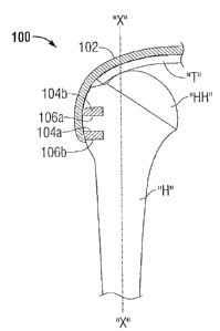
Referring now to Fig. 1, a bone-tendon assembly is illustrated for use with a
method for
repairing a rotator cuff tendon and is generally depicted as numeral 100. The
bone-tendon
assembly 100 includes a graft tendon 102 and one or more bone segments 104a
and 104b. The
graft tendon 102 is adapted to attach to a rotator cuff tendon T by any
suitable attaching
technique, for example, but not limited to, suturing, anchoring, or gluing. In
this illustration, the
bone-tendon assembly 100 includes two bone segments 104a and 104b (e.g., a
bone plug) which
are adapted to be received within a prepared host bed or bony defect formed in
a humeral head
HH of a humerus H. Each of bone plugs, 104a and 104b, is securely fastened to
a respective
bone defect 106a and 106b (e.g., hole or cavity). The bone defects 106a and
106b are created in
the bony surface of the top portion of the humerus H to allow bone segments
104a and 104b to
-6-
CA 02692205 2010-02-08
be secured therewithin. A more detailed explanation of a bone defect and its
preparation will be
described in further detail below.
Turning now to Fig. 2, the bone-tendon assembly 100 is shown before attachment
to the
rotator cuff tendon T. It is envisioned that the bone-tendon assembly 100 may
be about 1 min
thick, about 6-8cm long, and the graft tendon 102 may taper from about 2-5 cm,
i.e., where the
graft tendon 102 attaches to the rotator cuff tendon T, to about 1-2cm, i.e.,
near the bone segment
104. Further, bone segment 104 may be about l em long and about 3-6mm in
diameter. The
bone segments of the present disclosure may be made from cortical, cancellous
bone segments,
or both, which may be obtained from allogenic, autogenic, and/or xenogenic
sources.
In embodiments, bone-tendon assembly 100 of the present disclosure may be
constructed
from a xenograft (i.e., a graft from an animal other than a human), an
allograft (i.e., a graft from
another human or cadaver), and/or an autograft (e.g., a graft from the same
human) and/or an
appropriate synthetic or combinations of the above. The bone-tendon assembly
100 may be
harvested from a pes anserinus tendon complex, a gracilis muscle, or any other
compatible
muscle. The pes anserinus graft may be removed from a tibial insertion point
on a
proximal/medial location of a tibia. It is important to note that the bone
segment 104 of the
harvested graft, along with the attached tendon 102, may be kept intact and
not separated. In this
manner, the bone-tendon assembly 100 maintains a naturally, strong connection
between the
graft tendon 102 and the bone segment 104. Alternatively, the bone and tendon
may be
harvested or prepared separately and subsequently attached to one another by
appropriate means
including interference fit, pinning, gluing or other mechanical means. Also
depicted in Fig. 2, the
bone segment 104 may be cut and carved into a cylindrical shape, e.g., 3-6 mm
in diameter, such
-7-
CA 02692205 2010-02-08
that, it may be received by a conforming defect (i.e., 3-6 mm in diameter) in
the humerus H of a
patient. Alternative shapes are also contemplated, the receiving aperture in
the humerus would be
created to receive or correspond to the shape of the bone-tendon segment.
Also depicted in Figure 2 is an exemplary embodiment where the bone-tendon
graft is
provided with sutures attached to facilitate the implant procedure. This
approach provides the
benefit of reducing operating room time, and also allows for a more
sophisticated attachment of
the sutures to the graft to improve the biomechanical characteristics and
prevent potential failure
modes such as the suture cutting through the graft. Alternative or additional
pre-prepared
securement means are also contemplated to be integral to the bone-tendon
graft, including suture
anchors, or other mechanical securement devices. Alternatively the bone-tendon
graft may
include securement means such as biologically compatible adhesives, or other
non-traditional
means of establishing the repair construct.
In other embodiments, the bone-tendon assembly 100 may be constructed from a
xenograft of a porcine tibia. It may be beneficial to utilize porcine-derived
xenografts, since they
are not associated with prion-, bse-, or scrapie-type communicable diseases.
Porcine xenografts
may be processed by methods such as those used by Tissue Science Laboratories,
LLC (TSL).
TSL uses a system for preparing porcine dennis which may be used for hernia
and rotator cuff
repairs. These methods use enzymatic digestion (e.g., trypsin) to remove the
immunogenic
domains of collagen, to aid in decellularization, and to remove attached
glyoproteinacous
materials (e.g., cell-surface antigens, e.g. a-GAL). It is also known that
acetone may be utilized
to defat and decellularize the tissue for further reducing antigenicity. An
additional method
disclosed by TSL is a processing method that utilizes agents to crosslink
tissue. This results in a
-8-
CA 02692205 2010-02-08
material that has limited degradation and reduced immunological potential such
that there is a
high level of biocompatibility. The extent of cross-linking or biological
stabilization of the
bone-tendon assembly can be controlled in order to achieve the appropriate
balance between
preventing a very high resorption rate and a very low biological incorporation
and remodeling
rate. Cross-linking also has the capability of enhancing biornechanical
properties as it creates
chemical bonds between collagen fibrils.
The embodiments of Figs. 3-5 are similar with respect to the described bone-
tendon
assembly of Fig. 1 and will only be described herein to the extent necessary
to describe the
differences between the embodiments.
Turning now to Fig. 3, another exemplary embodiment of a bone-tendon assembly
200 is
illustrated. In this embodiment, bone-tendon assembly 200 joins the rotator
cuff tendon T and
the top portion of the humerus H by utilizing a graft tendon 202, a bone plug
204, a plurality of
sutures 208, and a suture anchor 210. It is envisioned that the bone-tendon
assembly 200 may be
attached, to the top portion of the humerus H and the rotator cuff tendon T by
any number of
bone plugs 204 and suture anchors 210. The suture anchors 210 are inserted and
secured into the
humeral head HH in a screw-type or an interference-type manner. The suture
anchor includes an
eyelet or other engagement structure to allow a suture to pass therethrough.
In this manner, the
suture is secured to the anchor. The suture anchors and the sutures may be
made of non-
absorbable or bioabsorbable material. The sutures 208 secure graft tendon 202
to the rotator cuff
tendon T. The bone plug 204 is configured to be inserted into a pre-drilled
defect 206 in the
humerus H, thereby creating a strong and secure bone-to-bone connection. In
this configuration,
the rotator cuff tendon T is securely attached to the humerus H via the bone-
graft assembly 200.
-9-
CA 02692205 2010-02-08
Fig. 4 illustrates another embodiment of a bone-tendon assembly 300 having a
graft
tendon 302, a bone plug 304, and a bone screw 312. The bone plug 304 is
attached to the top
portion of the humerus H in a similar manner as mentioned in the embodiments
above. The bone
screw 312, which may be bioabsorbable or non-absorbable, is configured to pass
through both,
graft tendon 302 and rotator cuff tendon T, to secure graft tendon 302 to
rotator cuff tendon T. In
this manner, the rotator cuff tendon T is attached to the bone-tendon assembly
300 by the bone
screw 312, while the bone plug 304 attaches the bone-tendon assembly 300 to
the humerus H.
Thus, the humerus H is securely attached to the rotator cuff tendon T via the
bone-tendon
assembly 300.
Fig. 5 illustrates a bone-tendon assembly 400 having a bone segment 404, a
graft tendon
402, one or more bone screws 412a and 412b, and a plurality of sutures 408. To
facilitate
securement of the bone-tendon assembly 400 to the humerus H, the bone screws
412a and 412b
are passed through the graft tendon 402 and the bone segment 404 and into the
humerus H. The
bone-tendon assembly 400 is also secured to the graft tendon 402 by sutures
408. In this manner,
the rotator cuff tendon T is securely attached to the humerus H via the bone-
tendon assembly
400.
Method for Repairing a Rotator Cuff Tear
A method of repairing a rotator cuff in a patient is further disclosed in the
present
disclosure. It should be noted that the method of repairing a rotator cuff in
the present disclosure
may be utilized with any one of the embodiments discussed above, namely, bone-
tendon
assemblies 100, 200, 300, and 400. Further, other bone-tendon assemblies, not
disclosed in the
present disclosure, may be utilized by the method discussed below. For
purposes of brevity, only
-10-
CA 02692205 2010-02-08
bone-tendon assembly 100 will be described in the method described below. It
should also be
noted that the methods described in the present disclosure may apply to the
repair of other
tendons in the human body. It should also be noted that this method of the
present disclosure
may be applied to repair bone-tendon mechanisms of animals other than humans.
The method includes accessing a surgical site, including a humerus H and a
rotator cuff
tendon T. The rotator cuff tendon T may be for example, a supraspinatus
tendon, an infraspinatus
tendon, a teres minor tendon, a subscapularis tendon, and/or a long head
tendon. Other potential
tendons in various anatomical locations are also contemplated. The surgical
site is accessed by
performing traditional open surgery, arthroscopic surgery, and/or a mini-open
surgery.
After the surgical site has been accessed, the rotator cuff tendon T is then
debrided, in
order to remove frayed intra-substance tissue from the torn tendon.
Afterwards, the rotator cuff
tendon T is pulled back into anatomical position and secured to the graft
tendon 102 by using
attaching means, for example, but not limited to, sutures, suture anchors,
etc. In some instances
the tendon may have shortened due to degeneration and contracture and may not
be able to be
reapposed to the anatomical insertion point without creating undue tension. In
these instances,
the bone-tendon assembly 100 can act as an intercalary `bridge' to span the
gap. In other
instances an open `window' remains after the repair and it is desirable to
close the hole which
may be responsible for residual pain in some patients.
The method of the present disclosure provides the capability of achieving both
of these
objectives, since the strong biomechanical properties of the disclosed
embodiments protect the
extensor mechanisms and facilitate natural healing. After a damaged rotator
cuff tendon T (e.g.,
a supraspinatus tendon) has been debrided, a foot-print in the top portion of
the humerus H is
-11-
CA 02692205 2010-02-08
prepared by performing a light decortication. This foot-print enhances
biological incorporation
and reattachment of the rotator cuff tendon T and/or bone-tendon assembly 100
to the humerus
H, thus recreating a natural-like insertion site. A defect is also created in
the humerus with a
configuration appropriate to correspond to the shape of the bone plug or bone
plugs, e.g., 104a
and 104b, of the bone tendon assembly 102.
Once the foot-print is prepared, a drilling instrument, or any other defect
creating device,
may be used to create the defect (e.g., hole or cavity) in humerus H. In
embodiments, a diameter
of the defect or defects, e.g., 106a and 106b, is dimensioned to be equal or
slightly smaller than a
diameter of the bone plug or plugs, e.g., 104a and 104b, such that, a
compression and/or
interference fit is created when the bone plug is firmly positioned within the
defect. It is also
anticipated that additional securement means may be utilized including
mechanical means such
as interference screws, etc, or other means such as adhesives, etc.
After the bone defect or defects, e.g., 106a and 106b, have been created, the
bone
segment or segments, e.g., 104a and 104b, are secured within the bone defects
by any suitable
press-fitting technique. The bone segments of the bone-tendon assembly 100 may
be shaped or
configured to be bone plugs. In embodiments, the shape of the bone segments
may be for
example, but not limited to, elliptical, rectangular, polygonal, cylindrical,
or triangular.
The bone to bone fit of a surface of the bone segment or segments within a
surface, e.g., a
wall, of the bone defect or defects creates an interference fit to minimize
irritation at the
operation site when the bone segment is inserted into the bone defect. Since
the presently
disclosed bone-tendon assemblies may be made of autografts, allografls, and/or
xenografts, the
natural shape of the bone segment or segments of the bone-tendon assembly may
not match the
12-
CA 02692205 2010-02-08
contours of the humeral head HH of the humerus H and/or the bone defect.
Therefore, accurate
measurements and preparation, e.g., shaping of the bone segment of the bone
graft assembly 100
and the bone defect are taken in order to avoid potential complications (e.g.,
rubbing of
surrounding tissues). This requires the length, width, and depth measurements
of the bone
segment of the bone-tendon assembly 100 to match the measurements of the bone
defect of the
prepared humerus H. Further, the contour of the bone-tendon assembly 100 may
also be
matched to the contour of the humeral head HH of the humerus H.
The bone segment of the bone-tendon assembly 100 is attached to the rotator
cuff tendon
T by an attaching technique, for example, but not limited to, anchoring,
suturing, adhering with a
bioadhesive, screwing, plugging, or press-fitting. A useful and beneficial
feature of the presently
disclosed bone-tendon assembly 100 is the ability to accurately measure the
length of the graft
tendon needed to avoid over-tensioning of the rotator cuff tendon T or any
other native tendons,
when the bone-tendon assembly is anatomically attached.
Next, the graft tendon 102 is attached to the rotator cuff tendon T by
different attaching
means, for example, but not limited to, clips, sutures, barbed sutures,
bioadhesives, and/or any
combinations thereof.
In embodiments, one or more dehydrated (e.g., lyophilized) bone segments 104
may be
utilized in conjunction with any of the aforementioned embodiments discussed
above. When the
bone segments, e.g., 104a and 104b, are dehydrated or lyophilized, this
results in shrinkage of
the bone segments. In this configuration, dehydrated bone segments 104a and
104b may be
positioned within the pre-drilled and/or shaped defects of humerus H,
whereupon rehydration of
-13-
CA 02692205 2010-02-08
bone segments will hydrate and expand to fill the defects, thus creating a
tight, compressed fit
between the bone plug and the defect.
In embodiments, additional biologically active materials may be added to
enhance
healing of the bone-tendon assembly to the humerus H and the tendon T, which
may include
growth factors, demineralized bone matrix, cells, genes, peptides, drugs
(including polymer
drugs) growth factors (Bone Morphogenic Proteins such as BMP-2, 4, 7, 12, or
14; Platelet
Derived Growth Factors e.g. PDGF-(3; Insulin-Like Growth Factors, Fibroblast
Growth Factors,
or other appropriate growth factors), cells (autogenous, allogenic or
xenogeneic fibroblasts,
muscle, fat, mesenchymal stem cells, or other appropriate cells) or other
agents which may
facilitate the healing process. These biologically active materials may be
combined with any of
the devices and materials utilized in the present disclosure including, but
not limited to, tendons,
sutures, adhesives, etc. Furthermore, these biologically active materials may
be applied in situ as
a solution or spray.
In other embodiments, the one or more defects may be positioned at a location
generally
perpendicular to a longitudinal axis X of the humerus, which is depicted in
Figs. I and 3-5. In
other embodiments, the defect may be positioned at a location generally
tangential to a radius of
curvature of the outer surface of the humeral head HH of the humerus H.
In addition, the thickness of the graft tendon can be matched to be
appropriate for a
particular individual such that the construct does not become too bulky and
create
rubbing/impingement on anatomical structures. The thickness is typically about
1-2mm.
In experiments, benchmark biomechanical properties for tendon repair products
have
shown 15% ultimate strain, approximately 15 mpa ultimate stress, 500-1000N
ultimate load,
-14-
CA 02692205 2010-02-08
approximately 150 mpa modulus, and 75-150 n/min stiffness. These parameters
are significantly
lower the native rotator cuff tendons, indicating the need for a more
biomechanically appropriate
assembly as disclosed in the embodiments. Thus, initial stiffness is a key
parameter in order to
support the construct and protect the native tendon during the healing
process.
In embodiments, energy may be applied to the surgical site, including for
example, but
not limited to, ultrasonic energy, pulsed electromagnetic field energy,
current energy, and/or
pressure-hyperbaric energy. It is known that applying energy to a surgical
site, especially during
or after a surgical operation, promotes rapid and effective healing.
Although the illustrative embodiments of the present disclosure have been
described
herein with reference to the accompanying drawings, it is to be understood
that the disclosure is
not limited to those precise embodiments and that various other changes and
modifications may
be effect therein by one skilled in the art without departing from the scope
or spirit of the
disclosure.
15-