Note: Descriptions are shown in the official language in which they were submitted.
CA 02692272 2009-12-23
WO 2009/005976
PCT/US2008/066528
METHOD AND APPARATUS FOR CONTROLLING PRECESSION IN
A DRILLING ASSEMBLY
BACKGROUND OF THE INVENTION
Field of the Invention
[01] Methods and devices consistent with the present invention
relate to a structure and method of controlling precession when drilling and,
more particularly, to controlling precession through the unbalanced radial
biasing of blades and the use of free sliding axial blade contacts in a fixed
stabilizer.
Description of the Related Art
[02] In a drilling assembly for drilling for oil and the like, a "non-
rotating" part may be used which does not rotate with the drill bit. For
example, a non-rotating stabilizer may be used. However, although the non-
rotating stabilizer does not rotate along with the drill bit, the non-rotating
stabilizer may rotate due to precession because of other forces associated
with
drilling, such as lateral and axial forces. In at least some instances it may
be
advantageous to control the non-rotating stabilizer, or some other non-
rotating
part, so that it does not rotate due to precession. One environment in which
it
can be beneficial to limit the rotation of a non-rotating stabilizer is when
the
non-rotating stabilizer is used in a directional drilling assembly.
CA 02692272 2009-12-23
WO 2009/005976
PCT/US2008/066528
[03] In related art, there are proposed methods for controlling the
direction of drilling, such that the drill bit may be moved from vertical
drilling
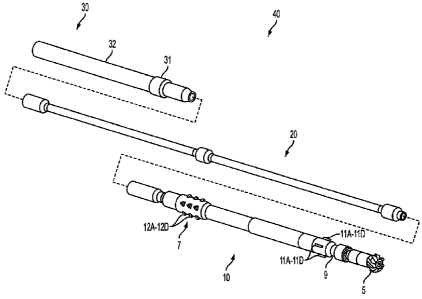
to drilling in a particular direction. One method for accomplishing
directional
drilling is shown by U.S. Patent No. 5,931,239 ("the '239 patent"), which is
incorporated herein by reference. In the '239 patent, the direction of
drilling is
controlled by extending and retracting stabilizer blades in an adjustable
stabilizer portion of a non-rotating stabilizer. In a non-limiting embodiment
of
the patent, there are four such stabilizer blades. When one of the stabilizer
blades is extended and the opposite blade is retracted, the drilling assembly
drills towards the retracted stabilizer blade (and away from the opposing
extended stabilizer blade).
[04] However, rotation of the non-rotating stabilizer can cause
problems with the directional control. Particularly, because the adjustable
blades which control the drilling direction rotate along with the non-rotating
stabilizer, when the non-rotating stabilizer rotates, the shifted position of
the
adjustable blades changes the direction in which the blades urge the drilling
assembly. For example, to turn the drilling bit of the drilling assembly in a
left direction, a left blade is retracted and a right blade is extended. If
the non-
rotating stabilizer then rotates a half-turn (180 degrees), the position of
the
blades are switched. Accordingly, the originally retracted blade moves from
the left side to the right side and the originally extended blade moves from
the
right side to the left side. In this manner, rotation of the non-rotating
stabilizer
moves the blades to a position of turning the drilling assembly to the right
2
CA 02692272 2009-12-23
WO 2009/005976
PCT/US2008/066528
rather than the left. It is thus difficult to control drilling to proceed in a
particular direction when the non-rotating stabilizer rotates due to
precession.
[05] The drilling apparatus can be programmed to adjust the blades
as the non-rotating stabilizer turns in order to counteract the rotation.
However, if the non-rotating stabilizer turns too quickly, adjustments to the
blades cannot keep pace with the rotation. Furthermore, controlling the
direction of the drilling is easier if the non-rotating stabilizer turns
slower or
not at all.
[06] Accordingly, it would be advantageous to be able to limit the
precession of a non-rotating part such as a stabilizer.
SUMMARY OF THE INVENTION
[07] The present invention provides apparatuses and methods for
controlling precession.
[08] According to an aspect of the present invention, there is
provided a drilling apparatus including: a non-rotating stabilizer; the non-
rotating stabilizer including a first blade and a second blade, the first
blade
being arranged opposite the second blade; wherein the first blade is biased
radially outwardly by a force of a first value; and wherein the second blade
is
not biased radially outwardly by a force corresponding to the first value.
[09] The second blade may be biased radially outwardly by a force
which is lower than the first value.
3
CA 02692272 2009-12-23
WO 2009/005976
PCT/US2008/066528
[10] The second blade may be biased radially outwardly by
substantially no force.
[11] The force of the first value biasing the first blade may be
provided by a spring.
[12] The non-rotating stabilizer may include a fixed stabilizer and
an adjustable stabilizer and the first blade and the second blade may be part
of
the fixed stabilizer.
[13] The adjustable stabilizer may comprise a plurality of adjustable
stabilizer blades which are extendable.
[14] The second blade may be slidably attached to the non-rotating
stabilizer in an axial direction of the non-rotating stabilizer.
[15] The second blade may be slidably attached such that the second
blade can move at least 0.3 inches in the axial direction.
[16] The second blade may be slidably attached such that the second
blade can move at least 0.5 inches in the axial direction.
[17] According to another aspect of the present invention, there is
provided a drilling apparatus comprising a non-rotating stabilizer comprising
a
fixed stabilizer; wherein the fixed stabilizer comprises a plurality of
blades;
wherein at least one of the plurality of blades of the fixed stabilizer is
biased
radially outwardly by a force different than another one of the plurality of
blades.
[18] Another one of the plurality of blades may be biased radially
outwardly by substantially no force.
4
CA 02692272 2009-12-23
WO 2009/005976
PCT/US2008/066528
[19] The plurality of blades may comprise four blades
circumferentially arranged around the non-rotating stabilizer.
[20] The plurality of blades may comprise five blades
circumferentially arranged around the non-rotating stabilizer.
[21] The plurality of blades may comprise six blades
circumferentially arranged around the non-rotating stabilizer.
[22] According to another aspect of the present invention, there is
provided a drilling apparatus comprising: a non-rotating stabilizer comprising
a fixed stabilizer; wherein the fixed stabilizer comprises a plurality of
blades;
wherein at least one of the plurality of blades of the fixed stabilizer is
slidable
along the non-rotating stabilizer in an axial direction of the non-rotating
stabilizer.
[23] At least one of the plurality of blades may be slidable at least
0.1 inches in the axial direction.
[24] At least one of the plurality of blades may be slidable at least
0.3 inches in the axial direction.
[25] At least one of the plurality of blades may be slidable at least
0.5 inches in the axial direction.
[26] The non-rotating stabilizer further may comprise an adjustable
stabilizer, the adjustable stabilizer comprising a plurality of adjustable
blades
which are extendable and retractable.
[27] According to another aspect of the present invention, there is
provided a drilling apparatus comprising: a non-rotating stabilizer comprising
CA 02692272 2009-12-23
WO 2009/005976
PCT/US2008/066528
a first blade, a second blade, a third blade and a fourth blade arranged
around
the circumference of the non-rotating stabilizer; wherein the first and second
blades are spring loaded by springs of a first spring constant; and wherein
the
third blade is opposite the first blade and the fourth blade is opposite the
second blade and the third blade and the fourth blade are not spring loaded.
BRIEF DESCRIPTION OF THE DRAWINGS
[28] The above aspects and features of the present invention will be
more apparent by describing certain embodiments of the present invention
with reference to the accompanying drawings, in which:
[29] FIG. 1 illustrates an exemplary embodiment of a drilling
assembly;
[30] FIG. 2 illustrates precession mechanics in a "smooth mode";
[31] FIG. 3 illustrates precession mechanics in a "vibrating mode"
[32] FIG. 4 is an explanatory illustration of clockwise precession
induced by lateral vibration and torque; and
[33] FIG. 5 illustrates an exemplary embodiment of the blades of a
fixed stabilizer.
DETAILED DESCRIPTION OF THE EXEMPLARY EMBODIMENTS
[34] Exemplary embodiments of the invention will now be
described below with reference to the attached drawings. The described
exemplary embodiments are intended to assist the understanding of the
invention, and are not intended to limit the scope of the invention in any
way.
6
CA 02692272 2009-12-23
WO 2009/005976
PCT/US2008/066528
In the following description, the same drawing reference numerals are used for
the same elements throughout.
[35] Fig. 1 shows an assembly for a directionally controlled drilling
system 40. The drilling system 40 includes a communications link 30, a non-
rotating stabilizer 10 and a flex joint 20 which joins the communications link
30 and the non-rotating stabilizer. The communications link includes an
antenna portion 32 and a spiral stabilizer 31. It is connected to one end of
the
flex joint 20. The drilling system 40 also includes a drill bit 5 at an end
thereof. The drill bit 5 is rotatably driven to dig a bore hole in the ground.
This can be done through a motor, not shown.
[36] The non-rotating stabilizer 10 is attached to the opposite end of
the flex joint 20 and includes a fixed stabilizer 7, an adjustable stabilizer
9 and
an antenna portion 3 there between. The non-rotating stabilizer 10 does not
rotate with the drill bit 5. However, the non-rotating stabilizer 10 may
rotate if
acted upon by other forces.
[37] The adjustable stabilizer 9 may be of the type described in U.S.
Patent No. 5,931,239. In this exemplary embodiment the adjustable stabilizer
includes four adjustable blades 11A-11D. Each of the blades may extend or
retract to control the direction of drilling. As described above and in the
'239
patent, when one of the blades 11A-11D is extended, the drill bit 5 is urged
away from the extended blade. Conversely, the drill bit 5 is urged towards a
retracted blade. Accordingly, extension and retraction of the various
adjustable blades 11A-11D allows for the drilling system 40 to be steered.
7
CA 02692272 2009-12-23
WO 2009/005976
PCT/US2008/066528
[38] The non-rotating stabilizer 10 also includes a fixed stabilizer 7.
The fixed stabilizer 7 is connected to the adjustable stabilizer 9 through the
antenna portion 3. In the exemplary embodiment shown in Fig. 1, the fixed
stabilizer 7 includes four blades 12A-12D. Four blades allows for an even
number and a symmetrical arrangement. However, the number of blades is
not limited to four. Fewer or more than four blades could be used, for
example, two, three, five or six or more blades could be used.
[39] The inventors of the present application discovered that a
drilling assembly with a non-rotating stabilizer operated in two modes, a
"smooth mode" and a "vibrating mode".
Smooth Mode Precession
[40] In the "smooth mode", the precession rate follows the
mechanics of an axial sliding frictional contact that is subjected to a
clockwise
torsional input. This is shown in Fig. 2. In an experiment, a first example of
a
drilling system each of the blades of the fixed stabilizer were biased
radially
outwardly with similar spring loads. As the bit drills downward in Fig. 2, the
friction between the fixed blades and the formation generated an axial sliding
force. The fixed stabilizer also receives a torsional force generated by the
friction between the rotating drilling shaft and the non-rotating stabilizer
unit.
= This is depicted as the lateral torsional friction force in Fig. 2. The
dotted line
that connects these two vectors describes the precessional path of a fixed
stabilizer contact. In this mode, the precession rate can be calculated from
the
8
CA 02692272 2009-12-23
WO 2009/005976
PCT/US2008/066528
contact force and its axial sliding friction factor and the applied clockwise
torque. For a 4 bladed stabilizer:
PRS¨
(12=3601 2.T
Eql.
pi.D D040 f = FS) .......................................
PRS =Precession Rate for Smooth Mode, ..................... deg/ft drilled
D = Diameter of hole, ..................................... inch
T =Frictional torque between rotating shaft and non-rotating stabilizer,
inlb
f = Sliding friction factor between stabilizer contact and formation
f = .35 for water base drilling fluid
FS = Spring force on a fixed stabilizer contact .......... lbs
[41] With this mode, the designer can select the contact force that
provides acceptable precession rates for the expected frictional torque and
sliding friction factor. For 500 lb springs, a .35 friction coefficient, and
120
inlb torsional friction in a 8.5 in. hole, the smooth precession rate would be
6.5
degrees per ft oho1e.
Vibrating Mode Precession
[42] In the "vibrating mode" the observed precession rates were
many times greater than were calculated or observed in the smooth mode. In
this test, the inventors collected enough precession data to enable them to
calculate the sliding friction factor as a function of depth if they assumed
that
the smooth mode mechanics also applied to the vibrating mode. While in the
smooth mode the calculated friction factors were typically in the 0.25 to 0.5
range, which is reasonably close to an expected value of about 0.35 for drill
string friction in a water base mud environment. The inventors also observed
9
CA 02692272 2009-12-23
WO 2009/005976
PCT/US2008/066528
occasional values as high as 0.6 and 0.8, which they attribute to the
microscopic variations in the rock surface.
[43] However, while in the vibrating mode the calculated friction
factors were quite close to zero. This calculated friction factor of zero does
not make sense in the drilling environment. Such an environment would
clearly produce a friction factor significantly greater than zero. Thus, the
inventors concluded that some other mode of operation must have controlled
the precession mechanics during this time. The inventors most likely
explanation for the periods of excessive precession is that the bottom hole
assembly must have been severely vibrating during these periods.
[44] Many of the service companies that supply Measurement While
Drilling (MWD) tools report that dovvnhole acceleration measurements
frequently exceed 20 g (g-force), or more. Drilling assemblies experience
axial, lateral, and torsion vibrations, sometimes all at the same time. Non-
rotating units should not be affected by torsional vibrations. However, axial
and lateral vibrations can greatly increase the precession rates of a non-
rotating stabilizer. The most disruptive vibrations are axial and lateral
vibrations that occur at one of the resonant frequencies of the drilling
assembly.
[45] The inventors believe that axial vibration affects the precession
mechanics by greatly increasing the distance that the lateral stabilizer
contact
must move. Fig. 3 shows how axial motions can greatly increase the distance
CA 02692272 2009-12-23
WO 2009/005976
PCT/US2008/066528
traveled and the resulting precession rate. The increased axial motion alters
the smooth mode precession equation for a 4 bladed stabilizer as follows:
= _____________________________
(360.(12+3=RPM=2=AMP=60/R0/1= _______ 2* T
PRA .......................................................... .....Eq.2
pi. D D=40 f = FS)
PRA = Precession Rate for Axial Vibrations in the Vibrating Mode......deg/ft
drilled
RPM = Rotary Speed with Tr-cone bit ........................... rev/min
AMP = Amplitude of axial vibrations .......................... .inch
ROP = Drilling rate ........................................... ft/hr
D = Diameter of hole, ......................................... inch
T = Frictional torque between rotating shaft and non-rotating stabilizer
inlbs
f = Sliding friction factor between stabilizer contact and formation
f = .35 for water base drilling fluid
FS = Spring force on a fixed stabilizer contact ............... lbs
[46] If the tool described in the smooth example had an axial
vibration amplitude of 0.2 inch while drilling at 30 ft/hr with a rotary speed
of
80 revs/min the precession rate would increase to 110 degrees per ft drilled.
[47] Lateral vibrations can have a similar effect on precession. The
spring loaded stabilizers must have a minimum diameter that is smaller than
the bit and a maximum extension that is larger than bit diameter. In the
inventors first experimental drilling tool they used radial dimensions of a
1/16
in under gauge minimum and a 1/8 in. over gauge maximum. With equal
springs in each blade the inventors created a design that allowed the tool to
be
deflected laterally with very low loads. If the rotary speed matched a
resonant
frequency in the bottom hole assembly the lateral vibrations could begin with
11
CA 02692272 2009-12-23
WO 2009/005976
PCT/US2008/066528
very low oscillating loads. The oscillations and deflection energy would both
build because they matched a resonant frequency. The first tool would move
1/8 in. laterally as it alternately fully compressed the springs on opposite
sides
of the tool. The continuous frictional torque that is applied to the tool
causes
the lateral motion of the tool to rotate it rather than hold a steady
orientation.
Fig. 4 illustrates how the frictional torque creates this rotation.
[48] Fig. 4A-4D shows four stabilizer blades 15A-15D in a borehole
1. The stabilizer blades that are not aligned with the lateral oscillations
would
have to move in opposite directions if the tool kept the same orientation. One
blade would move clockwise and the other would have to move counter
clockwise. Because of the clockwise frictional torque it is much easier to
turn
a blade clockwise than counter clockwise. This causes the counter clockwise
blade to stay fixed in the hole and become a pivot point that allows the other
stabilizers on the tool to rotate clockwise about the pivot point. With
reference to the location of the blades in the figures, Fig. 4A shows the
upper
blade 15A being compressed and the lower blade 15C being extended. In this
situation, the left blade 15D acts as a pivot point so that the upper blade
15A
slides to the right, the right side blade 15B slides down and the bottom blade
15C slides to the left. As shown in Figs. C3 and C3, when the upper blade
15A is fully extended, the right side blade 15B acts as a pivot point and the
remaining blades 15A, 15C and 15D rotate clockwise. With each side to side
movement the tool rotates 1/8 in. circumferentially. This increases the
precession rate as indicated by the following:
12
CA 02692272 2009-12-23
WO 2009/005976
PCT/US2008/066528
(360*(12 __ + CPMe 2=AMP=601 ROP))( __ 20T )
PRL= ........................................................ Eg.3
pi= D D=4=f = FS
PPL =Precession Rate for Lateral Vibrations in Vibrating Mode .. deg/ft
drilled
CPM =Vibration frequency ...................................... cycles/min
AMP =Amplitude of lateral vibrations .......................... .inch
ROP =Drilling rate ............................................ .ft/hr
D =Diameter of hole, .......................................... . inch
T =Frictional torque between rotating shaft and non-rotating stabilizer
inlbs
f = Sliding friction factor between stabilizer contact and formation
f = .35 for water base drilling fluid
=
FS = Spring force on a fixed stabilizer contact ............... .lbs
[49] If the same frequency is experienced here as in the axial case,
then 1/8 in. lateral vibrations would generate a precession rate of 71 deg/ft
drilled.
[50] In view of the above, the present inventors discovered that
vibrations in the axial direction (in the up and down direction of the
borehole)
and vibrations in the lateral direction (causing the stabilizer to move from
side
to side in the borehole) cause rotation of the stabilizer. Accordingly, the
present inventors recognized that if axial and lateral vibrations could be
reduced, the rate of precession (rotation) could be reduced and the
directional
drilling could be better controlled.
[51] In the experiments above, each of the blades of the fixed
stabilizer is biased by a substantially equal spring force. When each of the
blades are biased by a similar force, it is not difficult to induce movement
of
the fixed stabilizer in the bore hole. For example, consider a fixed
stabilizer
13
CA 02692272 2009-12-23
WO 2009/005976
PCT/US2008/066528
with four blades with each blade being biased by a spring force of 500 lbs. In
order for the fixed stabilizer to be moved to the left, the spring biasing the
left
blade would have to be compressed. Generally, in order to compress the left
spring a force of greater than 500 lbs would be necessary. However, in the
situation described above, the spring biasing the right blade provides a force
tending to compress the spring biasing the left blade. Indeed, since the
spring
forces biasing each of the blades are similar, a much smaller force than 500
lbs
is necessary to compress the spring biasing the left blade. Indeed, generally
a
550 pound load would be required to compress a 500 lb spring 1/16th of an
inch and 460 pounds to relax it 1/16 of an inch. However, when there are
opposing blades each biased by 500 lb springs, the force required to oscillate
the tool by a 1/32 of an inch in any direction is only 45 pounds and only 90
pounds is required to move the blade 1/16 of an inch. Regardless of the
number of blades, when opposite blades are biased by a similar spring force
small forces can cause compression of the springs and movement of the blades.
In turn, this can cause precession. This provides an ideal condition for
building high energy resonant vibrations because they can begin with
extremely low energy deflections that can build because of resonance.
Accordingly, lateral vibrations of the stabilizer contacts are maximized
through the use of spring-loaded stabilizer blades.
[52] In order to limit precession caused by lateral vibration, the
drilling system according to an exemplary embodiment of the present
invention includes a fixed stabilizer which avoids symmetrical radial biasing
14
CA 02692272 2009-12-23
WO 2009/005976
PCT/US2008/066528
of the blades of the fixed stabilizer. Particularly, according to the
exemplary
embodiment, opposite blades in the fixed stabilizer 7 are not biased by a
similar spring force.
[53] An exemplary embodiment of the blades 12A-12D of a fixed
stabilizer according the present invention is shown in Fig. 5. In the
exemplary
embodiment, the top blade 12A and the right blade 12B are each biased in the
radial direction by respective biasing spring 15A, 15B. However, the blades
opposite the top blade 12A and the right blade 12B are not biased by springs.
Particularly, a bottom blade 12C opposite the top blade 12A is not radially
biased by a spring. Likewise, the left blade 12D, opposite the right blade 12B
is not radially biased by a spring.
[54] With springs in only two of the blades, the tool can only move
laterally, in one direction. If the lateral load is directed at the fixed
blades 12C,
12D which are not spring loaded, no motion is possible, regardless of the size
or load. These blades 12C, 12D are simply fixed in the lateral/radial
direction.
When the motion is directed towards the spring-loaded blades 12A, 12B, it
will require a lateral force of more than 500 pounds to get any motion. It
will
take 550 pounds to move 1/16th of an inch. By making the threshold for the
initial motion high enough, the development of resonant vibrations is
prevented. Thus, in the exemplary embodiment of the present invention
without an equal opposing spring force, 550 pounds is required to move 1/16th
of an inch. In the example described above with opposing spring forces, only
CA 02692272 2009-12-23
WO 2009/005976
PCT/US2008/066528
90 pounds load is required for a movement of 1/16th of an inch. Accordingly,
the exemplary embodiment suppresses lateral motion and vibration.
[55] The present exemplary embodiment can accommodate more
than one spring biasing each biased blade 12A, 12B. For example, there may
be three 500 lb springs biasing each blade. This would create a 1500 lb
minimum threshold for the lateral force that is required to initiate
vibrations.
The values and the number of springs is not particularly limited. However,
providing more numerous or rigid springs provide a higher barrier to lateral
movement. A biasing spring force on a single blade of at least 250 lbs may be
used to create a high barrier to lateral movement and a biasing force of at
least
500 lbs may be used to ensure that a sufficiently high barrier is created.
[56] Although this exemplary embodiment includes four blades, the
number of blades of the fixed stabilizer is not particularly limited and there
may be more or less than four blades. For example, there may be six blades in
which three adjacent blades being biased by a spring force and the opposing
three blades not being biased by a spring force. Alternatively, there may be
five blades with two or three adjacent blades being biased by a spring force
and the remaining two or three blades being biased by no spring force or a
substantially lower spring force.
[57] Furthermore, the exemplary embodiment includes two blades
12A, 12B which are biased by a spring force and two blades 12C, 12D which
are not biased by a spring force. The blades 12C, 12D may also be biased in
the radial direction by a spring force which is significantly lower than the
16
CA 02692272 2009-12-23
WO 2009/005976
PCT/US2008/066528
blades 12A, 12B, particularly a spring force which substantially different
enough so as to limit axial movement. For example, they may be biased by a
spring force that is at least 100 lbs lower than the spring force of the
blades
12A, 12B. In order to raise the barrier to lateral movement, they may also be
biased by a spring force that is at least 250 lbs lower or 500 lbs lower than
the
spring biasing blades 12A, 12B.
[58] The fixed stabilizer 7 of the exemplary embodiment is also
designed to control precession caused by axial vibrations. The precession
caused by axial vibrations is the result of the significant up and down
motion.
In order to address the precession caused by this axial direction, the
exemplary
embodiment mounts two of the blades 12C, 12D on free sliding axial supports
14. During normal downward drilling, the free sliding blades will ride on the
top end 14A of the free sliding support, as shown in Fig. 5. This is due to
the
friction acting on the free sliding blades 12C, 12D as they move downwardly.
The friction will oppose the downward motion and keep the free sliding blades
at the top end of their sliding position. On the other hand, if the non-
rotating
stabilizer begins bouncing up and down, the blades will remain in stationary
contact with the hole 1 whenever the tool bounces upward. That is, because of
the frictional contact between the blades 12C, 12D and the hole 1, the blades
tend to remain in the same place. Thus, when the bottom end of the drilling
assembly bounces upwardly, the non-rotating stabilizer is able to move
upwardly relative to the sliding blades 12C, 12D as the sliding blades 12C,
17
CA 02692272 2009-12-23
WO 2009/005976
PCT/US2008/066528
12D remain in the same position. The sliding blades slide relatively
downwardly towards the bottom of the free sliding support 14B.
[59] On the other hand, when the tool bounces downward, the top
end of the free sliding support 14A contacts the blades 12C, 12D to move
them in the downward direction with the rest of the non-rotating stabilizer.
This allows the bottom end of the drilling assembly to bounce up and down
while the blades 12C, 12D only move downward. This limits the total
distance moved by the free sliding blades 12C, 12D to the downward advance
of the drill bit and limits the precession rate of the non-rotating assembly
to
that predicted for the smooth mode. The coefficient of friction between the
blades 12C, 12D and the free sliding support 14 is much lower than the
coefficient of friction between the blades 12C, 12D and the hole 1. This
assures free sliding of the blades 12C, 12D rather than movement between the
blades 12C, 12D and the hole 1.
[60] If the free sliding length exceeds the amplitude of the axial
vibrations of the bottom end of the drilling assembly, there is only downward
motion of the free sliding of the blades 12C, 12D. The exemplary
embodiment shows a free sliding length of the blades 12C, 12D of 0.5 in.
Axial vibrations are estimated to be in the range of 0.1 to 0.3 in.
Accordingly,
a free sliding length is of at least 0.1 in limits the blades to downward
motion
in at least some instances. A free sliding length of at least 0.3 in should
provide enough sliding length in most conditions. A free sliding length of at
18
CA 02692272 2009-12-23
WO 2009/005976
PCT/US2008/066528
least 0.5 in. may be used to more certainly provide a sufficient free sliding
length.
[61] As noted above, the friction between the blades 12C, 12D and
the borehole 1 wall is greater than the friction between the blade and the
free
sliding support so that the blades 12C, 12D are held by the borehole wall and
move along the free sliding rail. The free sliding blade contacts may provide
formation friction factors that are at least three times as high as the pad to
rail
friction factors. Furthermore, the sliding surface of the sliding support upon
which the blades slide may be equipped with diamond bearings to
significantly increase the friction ratio. Contact portions of the sliding
support
and the pads may be manufactured from tungsten carbide to enhance life.
[62] In the exemplary embodiment of Fig. 5, each of the blades
12A-12D includes a number of pyramid shaped spikes 13. This shape helps to
increase the friction between the blades 12A-12D and the borehole 1. Using
45 sloped pyramids avoids generating bending loads on the contacts. The
tops of the pyramid shaped spikes may be flattened to ensure the required
lateral load capacity and to increase wear resistance. Also, in the exemplary
embodiment of Fig. 5, the spikes 13 are arranged in three rows of three. The
three rows of the exemplary embodiment are designed to provide equal
contacts in a gauge hole surface. The rows are also separated to promote self
cleaning of the spikes 13.
[63] Although the present invention has been described in
connection with the exemplary embodiments of the present invention, it will
19
CA 02692272 2016-01-14
WO 2009/005976
PCTIUS20mi1(166528
be apparent to those skilled in the art that various modifications and changes
may be made thereto.