Language selection

Search

Patent 2692316 Summary

Third-party information liability

Some of the information on this Web page has been provided by external sources. The Government of Canada is not responsible for the accuracy, reliability or currency of the information supplied by external sources. Users wishing to rely upon this information should consult directly with the source of the information. Content provided by external sources is not subject to official languages, privacy and accessibility requirements.

Claims and Abstract availability

Any discrepancies in the text and image of the Claims and Abstract are due to differing posting times. Text of the Claims and Abstract are posted:

  • At the time the application is open to public inspection;
  • At the time of issue of the patent (grant).
(12) Patent Application: (11) CA 2692316
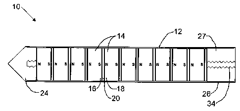
(54) English Title: MAGNETIC FILTER ELEMENTS
(54) French Title: ELEMENTS DE FILTRE MAGNETIQUES
Status: Deemed Abandoned and Beyond the Period of Reinstatement - Pending Response to Notice of Disregarded Communication
Bibliographic Data
(51) International Patent Classification (IPC):
  • B01D 35/06 (2006.01)
(72) Inventors :
  • MARCHAND, ROGER L. (Canada)
  • TSCHETTER, DOUGLAS J. (Canada)
(73) Owners :
  • BAY6 SOLUTIONS INC.
(71) Applicants :
  • BAY6 SOLUTIONS INC. (Canada)
(74) Agent: NATHAN V. WOODRUFFWOODRUFF, NATHAN V.
(74) Associate agent:
(45) Issued:
(22) Filed Date: 2010-02-12
(41) Open to Public Inspection: 2011-08-12
Examination requested: 2013-11-26
Availability of licence: N/A
Dedicated to the Public: N/A
(25) Language of filing: English

Patent Cooperation Treaty (PCT): No

(30) Application Priority Data: None

Abstracts

English Abstract


A magnetic filter element has an elongate non-magnetic housing and a series of
magnets arranged in a column within the housing. Each magnet has a north pole
and a south
pole. The plurality of magnets is arranged with the north poles adjacent to
the south poles of
adjacent magnets. Non-magnetic spacer elements separate the plurality of
magnets in the
column.


Claims

Note: Claims are shown in the official language in which they were submitted.

6
What is Claimed is:
1. A magnetic filter element, comprising:
an elongate non-magnetic housing;
a series of magnets arranged in a column within the housing, each magnet
having a
north pole and a south pole, the plurality of magnets being arranged with the
north poles
adjacent to the south poles of adjacent magnets; and
non-magnetic barrier separating the plurality of magnets in the column.
2. The magnetic filter element of claim 1, wherein the non-magnetic housing
comprises a
non-magnetic end cap that extends outward from the last magnet in the column
such that the
end cap forms a non-magnetic section at the end of the housing.
3. The magnetic filter element of claim 1, wherein the series of magnets are
spaced from a
mounting end of the housing to provide a non-magnetic section at the mounting
end of the
housing.
4. The magnetic filter element of claim 1, wherein the non-magnetic housing
comprises a
flange at a mounting end of the housing.
5. The magnetic filter element of claim 3, wherein the mounting end of the
housing
comprises external threads adjacent to the flange.
6. The magnetic filter element of claim 1, wherein a dipole moment of each
magnet is
parallel to the housing.
7. The magnetic filter element of claim 1, wherein a dipole moment of each
magnet is
perpendicular to the housing.
8. The magnetic filter element of claim 1, wherein the non-magnetic barrier is
a non-

7
magnetic spacer element.
9. The magnetic filter element of claim 1, wherein the non-magnetic barrier is
air.

Description

Note: Descriptions are shown in the official language in which they were submitted.


CA 02692316 2010-02-12
TITLE
[0001] Magnetic filter elements
FIELD
[0002] This relates to a magnetic filter element.
BACKGROUND
[0003] United States patent no. 6,143,171 (Van Aarsen) entitled "Magnetic
device for
treatment of fluids" describes a magnetic device that is used to remove
ferrous particles from
a fluid. The magnetic device has a series of magnets arranged in a column with
like poles
facing one another and separated by magnetically permeable discs.
SUMMARY
[0004] There is provided a magnetic filter element, comprising an elongate non-
magnetic
housing and a series of magnets arranged in a column within the housing. Each
magnet has a
north pole and a south pole. The plurality of magnets is arranged with the
north poles
adjacent to the south poles of adjacent magnets. Non-magnetic spacer elements
separate the
plurality of magnets in the column.
[0005] The non-magnetic housing may comprise a non-magnetic end cap that
extends
outward from the last magnet in the column such that the end cap forms a non-
magnetic
section at the end of the housing. The series of magnets may be spaced from a
mounting end
of the housing to provide a non-magnetic section at the mounting end of the
housing.
[0006] The non-magnetic housing comprises a flange at a mounting end of the
housing.
The mounting end of the housing may comprise external threads adjacent to the
flange.
[0007] A dipole moment of each magnet may be parallel or perpendicular to the
housing.
BRIEF DESCRIPTION OF THE DRAWINGS
[0008] These and other features will become more apparent from the following
description in which reference is made to the appended drawings, the drawings
are for the
purpose of illustration only and are not intended to be in any way limiting,
wherein:

CA 02692316 2010-02-12
2
FIG. 1 is a side elevation view in section of a magnetic filter element.
FIG. 2 is a side elevation view in section of an alternative magnetic filter
element.
FIG. 3 and 4 are side elevation views of alternative housings.
FIG. 5 is a perspective view of a series of magnets.
FIG. 6 and 7 are side elevation views of alternative non-magnetic barriers.
DETAILED DESCRIPTION
[0009] A magnetic filter element, generally identified by reference numeral
10, will now
be described with reference to FIG. 1 through 7.
Structure and Relationship of Parts:
[0010] Referring to FIG. 1, magnetic filter element 10 has an elongate non-
magnetic
housing 12 and a series of magnets 14 arranged in a column within housing 12.
Preferably,
magnets 14 are rare earth magnets, such as NdFeB magnets, or other strong
magnets. As
shown in the depicted embodiment, magnets 14 may be sized to fit closely
within housing 12.
Preferably, housing 12 is a cylindrical housing, and, referring to FIG. 4,
magnets 14 are
shorter cylinders or puck shaped to fit within housing 12. Referring to FIG.
1, each magnet
14 has a north pole 16 and a south pole 18. Magnets 14 are arranged such that
north poles 16
and south poles 18 of adjacent magnets 14 are adjacent, and are separated by a
non-magnetic
barrier 20. Magnets 14 may be oriented such that their dipole moments are
parallel to
housing 12 as shown in FIG. 1, such that there is only one north/south
interface on each side
of magnets 14. In other words, if each magnet 14 is puck shaped, magnet 14
varies from
north to south along its height. Alternatively, referring to FIG. 2, the
dipole moment of each
magnet may be perpendicular to housing 12, such that magnets 14 vary along the
width rather
than their height. This results in two north/south interfaces for each side of
magnets 14, and
results in a more complex magnetic field pattern.
[0011] When opposite magnetic poles are adjacent, the magnetic field lines are
densely
positioned around the interface. This can be contrasted with magnetic field
lines when like
poles are adjacent, which extend perpendicular to each other out to infinity.
Opposite poles
result in a magnetic attraction that is very strong close to the interface of
the magnets, but

CA 02692316 2010-02-12
3
tapers off quickly as one moves away from that interface. This can be used to
provide a
strong holding force on ferrous debris that is encountered in a liquid.
However, the debris
must get quite close to filter element 10 to be affected. As these opposed
poles are separated,
such as by non-magnetic barrier 20, the field lines move outward, such that
the strength of the
magnetic attraction close to the magnet is reduced somewhat, but extends
further outward.
Thus, there is a trade-off between the reach of the magnetic attraction, and
the strength of the
magnetic attraction. The size of the non-magnetic barrier 20 can be used to
select the desired
magnetic field. The design described herein is particularly useful in
situations where a
moving fluid is to be filtered, such as in engine lubrication systems,
hydraulic equipment or
other mechanical devices.
[0012] Non-magnetic barrier 20 may take different forms. For example, FIG. 6
shows a
non-magnetic spacer element 21, such as a disc, which may be composed of
various non-
magnetic materials and may have various thicknesses. Alternatively, non-
magnetic spacer
element 20 may be formed from a fluid. FIG. 7 depicts how this may be done by
providing
magnets 14 with protrusions 22 on the end of each magnet 14. The space may
then be filled
with a non-magnetic gas or liquid. While protrusions 22 may be magnetic, the
amount of
magnetic material will be small enough to minimize their effect on the
operation of filter
element 10.
[0013] In other embodiments, filter element 10 preferably has non-magnetic
portions at
one or both ends. Referring to FIG. 1, non-magnetic housing 12 may have a non-
magnetic
end cap 24 that extends outward from the last magnet 14 in the column such
that end cap 24
forms a non-magnetic section at the end of housing 12. This may be useful, for
example,
when cleaning a filter element, as the captured particles can be pushed toward
the non-
magnetic end where they are more easily removed. In addition, this may also
help avoid
inducing a magnetic dipole in the machinery that is close to end cap 24.
Similarly, there may
be a non-magnetic portion at a mounting end 26 of housing 12 formed by a non-
magnetic
element 27.
[0014] In order to install filter element 10, non-magnetic housing 12 may have
threads 28

CA 02692316 2010-02-12
4
at mounting end 26 as shown in FIG. 3, a flange 30 as shown in FIG. 4, or
both. The
embodiment in FIG. 3 may be threaded into an aperture, while the embodiment in
FIG. 4
may be pin-connected into an aperture through holes 32.
Operation:
[0015] The embodiments shown in FIG.1 and 2 are assembled by providing a non-
magnetic housing 12. Magnets 14 are inserted into housing 12 to form non-
magnetic barriers
20 between each magnetic, and such that opposite poles are adjacent. End cap
24 and a non-
magnetic element 27 are provided, and the entire structure may be held
together by inserting a
threaded rod 34. As shown in FIG. 5, magnets 14 preferably have a central
aperture 35 to
facilitate this. Referring to FIG. 3 and 4, to facilitate installation,
housing 12 may have
threads 28, a flange 30, or both. Element 10 may then be installed such that
magnets 14 exert
a force on magnetic particles and debris in a fluid. Magnetic filter element
10 is particularly
useful for filtering moving fluids in relatively small spaces, and may be
inserted through an
aperture in a tank wall, such as in an engine lubrication system, hydraulic
equipment or other
mechanical devices.
[0016] To clean filter element 10, it is first removed from the fluid, and may
be wiped
clean by starting at the non-magnetic section at mounting end 26 and moving
toward non-
magnetic end cap 24. Alternatively, it may be pressure washed, or otherwise
cleaned as will
be recognized by those in the art.
[0017] In this patent document, the word "comprising" is used in its non-
limiting sense to
mean that items following the word are included, but items not specifically
mentioned are not
excluded. A reference to an element by the indefinite article "a" does not
exclude the
possibility that more than one element is present, unless the context clearly
requires that there
be one and only one of the elements.
[0018] The following claims are to be understood to include what is
specifically
illustrated and described above, what is conceptually equivalent, and what can
be obviously
substituted. Those skilled in the art will appreciate that various adaptations
and modifications

CA 02692316 2010-02-12
of the described embodiments can be configured without departing from the
scope of the
claims. The illustrated embodiments have been set forth only as examples and
should not be
taken as limiting the invention. It is to be understood that, within the scope
of the following
claims, the invention may be practiced other than as specifically illustrated
and described.

Representative Drawing
A single figure which represents the drawing illustrating the invention.
Administrative Status

2024-08-01:As part of the Next Generation Patents (NGP) transition, the Canadian Patents Database (CPD) now contains a more detailed Event History, which replicates the Event Log of our new back-office solution.

Please note that "Inactive:" events refers to events no longer in use in our new back-office solution.

For a clearer understanding of the status of the application/patent presented on this page, the site Disclaimer , as well as the definitions for Patent , Event History , Maintenance Fee  and Payment History  should be consulted.

Event History

Description Date
Inactive: Dead - No reply to s.30(2) Rules requisition 2016-08-04
Application Not Reinstated by Deadline 2016-08-04
Deemed Abandoned - Failure to Respond to Maintenance Fee Notice 2016-02-12
Inactive: Abandoned - No reply to s.30(2) Rules requisition 2015-08-04
Inactive: S.30(2) Rules - Examiner requisition 2015-02-04
Inactive: Report - No QC 2015-01-22
Letter Sent 2013-12-03
All Requirements for Examination Determined Compliant 2013-11-26
Request for Examination Requirements Determined Compliant 2013-11-26
Request for Examination Received 2013-11-26
Application Published (Open to Public Inspection) 2011-08-12
Inactive: Cover page published 2011-08-11
Inactive: Office letter 2011-04-26
Appointment of Agent Requirements Determined Compliant 2011-04-26
Revocation of Agent Requirements Determined Compliant 2011-04-26
Inactive: Office letter 2011-04-26
Inactive: Declaration of entitlement - Formalities 2011-04-21
Inactive: Declaration of entitlement - PCT 2011-04-21
Inactive: IPC assigned 2010-03-12
Inactive: First IPC assigned 2010-03-12
Application Received - Regular National 2010-03-08
Filing Requirements Determined Compliant 2010-03-08
Reinstatement Requirements Deemed Compliant for All Abandonment Reasons 2010-03-08
Inactive: Filing certificate - No RFE (English) 2010-03-08
Small Entity Declaration Determined Compliant 2010-02-12

Abandonment History

Abandonment Date Reason Reinstatement Date
2016-02-12

Maintenance Fee

The last payment was received on 2014-12-18

Note : If the full payment has not been received on or before the date indicated, a further fee may be required which may be one of the following

  • the reinstatement fee;
  • the late payment fee; or
  • additional fee to reverse deemed expiry.

Please refer to the CIPO Patent Fees web page to see all current fee amounts.

Fee History

Fee Type Anniversary Year Due Date Paid Date
Application fee - small 2010-02-12
MF (application, 2nd anniv.) - small 02 2012-02-13 2011-11-29
MF (application, 3rd anniv.) - small 03 2013-02-12 2012-11-23
MF (application, 4th anniv.) - small 04 2014-02-12 2013-11-26
Request for examination - small 2013-11-26
MF (application, 5th anniv.) - small 05 2015-02-12 2014-12-18
Owners on Record

Note: Records showing the ownership history in alphabetical order.

Current Owners on Record
BAY6 SOLUTIONS INC.
Past Owners on Record
DOUGLAS J. TSCHETTER
ROGER L. MARCHAND
Past Owners that do not appear in the "Owners on Record" listing will appear in other documentation within the application.
Documents

To view selected files, please enter reCAPTCHA code :


To view images, click a link in the Document Description column. To download the documents, select one or more checkboxes in the first column and then click the "Download Selected in PDF format (Zip Archive)" or the "Download Selected as Single PDF" button.

List of published and non-published patent-specific documents on the CPD .

If you have any difficulty accessing content, you can call the Client Service Centre at 1-866-997-1936 or send them an e-mail at CIPO Client Service Centre.


Document
Description 
Date
(yyyy-mm-dd) 
Number of pages   Size of Image (KB) 
Description 2010-02-12 5 190
Abstract 2010-02-12 1 10
Claims 2010-02-12 2 34
Drawings 2010-02-12 3 28
Representative drawing 2011-07-14 1 7
Cover Page 2011-07-25 1 30
Filing Certificate (English) 2010-03-08 1 157
Reminder of maintenance fee due 2011-10-13 1 112
Acknowledgement of Request for Examination 2013-12-03 1 176
Courtesy - Abandonment Letter (R30(2)) 2015-09-29 1 163
Courtesy - Abandonment Letter (Maintenance Fee) 2016-03-29 1 170
Correspondence 2010-03-08 1 12
Correspondence 2010-03-08 1 18
Correspondence 2010-03-08 1 62
Correspondence 2011-03-31 3 159
Correspondence 2011-04-26 1 17
Correspondence 2011-04-26 1 22
Correspondence 2011-04-21 1 25