Sélection de la langue

Search

Sommaire du brevet 2692316 

Énoncé de désistement de responsabilité concernant l'information provenant de tiers

Une partie des informations de ce site Web a été fournie par des sources externes. Le gouvernement du Canada n'assume aucune responsabilité concernant la précision, l'actualité ou la fiabilité des informations fournies par les sources externes. Les utilisateurs qui désirent employer cette information devraient consulter directement la source des informations. Le contenu fourni par les sources externes n'est pas assujetti aux exigences sur les langues officielles, la protection des renseignements personnels et l'accessibilité.

Disponibilité de l'Abrégé et des Revendications

L'apparition de différences dans le texte et l'image des Revendications et de l'Abrégé dépend du moment auquel le document est publié. Les textes des Revendications et de l'Abrégé sont affichés :

  • lorsque la demande peut être examinée par le public;
  • lorsque le brevet est émis (délivrance).
(12) Demande de brevet: (11) CA 2692316
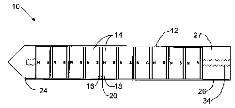
(54) Titre français: ELEMENTS DE FILTRE MAGNETIQUES
(54) Titre anglais: MAGNETIC FILTER ELEMENTS
Statut: Réputée abandonnée et au-delà du délai pour le rétablissement - en attente de la réponse à l’avis de communication rejetée
Données bibliographiques
Abrégés

Abrégé anglais


A magnetic filter element has an elongate non-magnetic housing and a series of
magnets arranged in a column within the housing. Each magnet has a north pole
and a south
pole. The plurality of magnets is arranged with the north poles adjacent to
the south poles of
adjacent magnets. Non-magnetic spacer elements separate the plurality of
magnets in the
column.

Revendications

Note : Les revendications sont présentées dans la langue officielle dans laquelle elles ont été soumises.


6
What is Claimed is:
1. A magnetic filter element, comprising:
an elongate non-magnetic housing;
a series of magnets arranged in a column within the housing, each magnet
having a
north pole and a south pole, the plurality of magnets being arranged with the
north poles
adjacent to the south poles of adjacent magnets; and
non-magnetic barrier separating the plurality of magnets in the column.
2. The magnetic filter element of claim 1, wherein the non-magnetic housing
comprises a
non-magnetic end cap that extends outward from the last magnet in the column
such that the
end cap forms a non-magnetic section at the end of the housing.
3. The magnetic filter element of claim 1, wherein the series of magnets are
spaced from a
mounting end of the housing to provide a non-magnetic section at the mounting
end of the
housing.
4. The magnetic filter element of claim 1, wherein the non-magnetic housing
comprises a
flange at a mounting end of the housing.
5. The magnetic filter element of claim 3, wherein the mounting end of the
housing
comprises external threads adjacent to the flange.
6. The magnetic filter element of claim 1, wherein a dipole moment of each
magnet is
parallel to the housing.
7. The magnetic filter element of claim 1, wherein a dipole moment of each
magnet is
perpendicular to the housing.
8. The magnetic filter element of claim 1, wherein the non-magnetic barrier is
a non-

7
magnetic spacer element.
9. The magnetic filter element of claim 1, wherein the non-magnetic barrier is
air.

Description

Note : Les descriptions sont présentées dans la langue officielle dans laquelle elles ont été soumises.

CA 02692316 2010-02-12
TITLE
[0001] Magnetic filter elements
FIELD
[0002] This relates to a magnetic filter element.
BACKGROUND
[0003] United States patent no. 6,143,171 (Van Aarsen) entitled "Magnetic
device for
treatment of fluids" describes a magnetic device that is used to remove
ferrous particles from
a fluid. The magnetic device has a series of magnets arranged in a column with
like poles
facing one another and separated by magnetically permeable discs.
SUMMARY
[0004] There is provided a magnetic filter element, comprising an elongate non-
magnetic
housing and a series of magnets arranged in a column within the housing. Each
magnet has a
north pole and a south pole. The plurality of magnets is arranged with the
north poles
adjacent to the south poles of adjacent magnets. Non-magnetic spacer elements
separate the
plurality of magnets in the column.
[0005] The non-magnetic housing may comprise a non-magnetic end cap that
extends
outward from the last magnet in the column such that the end cap forms a non-
magnetic
section at the end of the housing. The series of magnets may be spaced from a
mounting end
of the housing to provide a non-magnetic section at the mounting end of the
housing.
[0006] The non-magnetic housing comprises a flange at a mounting end of the
housing.
The mounting end of the housing may comprise external threads adjacent to the
flange.
[0007] A dipole moment of each magnet may be parallel or perpendicular to the
housing.
BRIEF DESCRIPTION OF THE DRAWINGS
[0008] These and other features will become more apparent from the following
description in which reference is made to the appended drawings, the drawings
are for the
purpose of illustration only and are not intended to be in any way limiting,
wherein:

CA 02692316 2010-02-12
2
FIG. 1 is a side elevation view in section of a magnetic filter element.
FIG. 2 is a side elevation view in section of an alternative magnetic filter
element.
FIG. 3 and 4 are side elevation views of alternative housings.
FIG. 5 is a perspective view of a series of magnets.
FIG. 6 and 7 are side elevation views of alternative non-magnetic barriers.
DETAILED DESCRIPTION
[0009] A magnetic filter element, generally identified by reference numeral
10, will now
be described with reference to FIG. 1 through 7.
Structure and Relationship of Parts:
[0010] Referring to FIG. 1, magnetic filter element 10 has an elongate non-
magnetic
housing 12 and a series of magnets 14 arranged in a column within housing 12.
Preferably,
magnets 14 are rare earth magnets, such as NdFeB magnets, or other strong
magnets. As
shown in the depicted embodiment, magnets 14 may be sized to fit closely
within housing 12.
Preferably, housing 12 is a cylindrical housing, and, referring to FIG. 4,
magnets 14 are
shorter cylinders or puck shaped to fit within housing 12. Referring to FIG.
1, each magnet
14 has a north pole 16 and a south pole 18. Magnets 14 are arranged such that
north poles 16
and south poles 18 of adjacent magnets 14 are adjacent, and are separated by a
non-magnetic
barrier 20. Magnets 14 may be oriented such that their dipole moments are
parallel to
housing 12 as shown in FIG. 1, such that there is only one north/south
interface on each side
of magnets 14. In other words, if each magnet 14 is puck shaped, magnet 14
varies from
north to south along its height. Alternatively, referring to FIG. 2, the
dipole moment of each
magnet may be perpendicular to housing 12, such that magnets 14 vary along the
width rather
than their height. This results in two north/south interfaces for each side of
magnets 14, and
results in a more complex magnetic field pattern.
[0011] When opposite magnetic poles are adjacent, the magnetic field lines are
densely
positioned around the interface. This can be contrasted with magnetic field
lines when like
poles are adjacent, which extend perpendicular to each other out to infinity.
Opposite poles
result in a magnetic attraction that is very strong close to the interface of
the magnets, but

CA 02692316 2010-02-12
3
tapers off quickly as one moves away from that interface. This can be used to
provide a
strong holding force on ferrous debris that is encountered in a liquid.
However, the debris
must get quite close to filter element 10 to be affected. As these opposed
poles are separated,
such as by non-magnetic barrier 20, the field lines move outward, such that
the strength of the
magnetic attraction close to the magnet is reduced somewhat, but extends
further outward.
Thus, there is a trade-off between the reach of the magnetic attraction, and
the strength of the
magnetic attraction. The size of the non-magnetic barrier 20 can be used to
select the desired
magnetic field. The design described herein is particularly useful in
situations where a
moving fluid is to be filtered, such as in engine lubrication systems,
hydraulic equipment or
other mechanical devices.
[0012] Non-magnetic barrier 20 may take different forms. For example, FIG. 6
shows a
non-magnetic spacer element 21, such as a disc, which may be composed of
various non-
magnetic materials and may have various thicknesses. Alternatively, non-
magnetic spacer
element 20 may be formed from a fluid. FIG. 7 depicts how this may be done by
providing
magnets 14 with protrusions 22 on the end of each magnet 14. The space may
then be filled
with a non-magnetic gas or liquid. While protrusions 22 may be magnetic, the
amount of
magnetic material will be small enough to minimize their effect on the
operation of filter
element 10.
[0013] In other embodiments, filter element 10 preferably has non-magnetic
portions at
one or both ends. Referring to FIG. 1, non-magnetic housing 12 may have a non-
magnetic
end cap 24 that extends outward from the last magnet 14 in the column such
that end cap 24
forms a non-magnetic section at the end of housing 12. This may be useful, for
example,
when cleaning a filter element, as the captured particles can be pushed toward
the non-
magnetic end where they are more easily removed. In addition, this may also
help avoid
inducing a magnetic dipole in the machinery that is close to end cap 24.
Similarly, there may
be a non-magnetic portion at a mounting end 26 of housing 12 formed by a non-
magnetic
element 27.
[0014] In order to install filter element 10, non-magnetic housing 12 may have
threads 28

CA 02692316 2010-02-12
4
at mounting end 26 as shown in FIG. 3, a flange 30 as shown in FIG. 4, or
both. The
embodiment in FIG. 3 may be threaded into an aperture, while the embodiment in
FIG. 4
may be pin-connected into an aperture through holes 32.
Operation:
[0015] The embodiments shown in FIG.1 and 2 are assembled by providing a non-
magnetic housing 12. Magnets 14 are inserted into housing 12 to form non-
magnetic barriers
20 between each magnetic, and such that opposite poles are adjacent. End cap
24 and a non-
magnetic element 27 are provided, and the entire structure may be held
together by inserting a
threaded rod 34. As shown in FIG. 5, magnets 14 preferably have a central
aperture 35 to
facilitate this. Referring to FIG. 3 and 4, to facilitate installation,
housing 12 may have
threads 28, a flange 30, or both. Element 10 may then be installed such that
magnets 14 exert
a force on magnetic particles and debris in a fluid. Magnetic filter element
10 is particularly
useful for filtering moving fluids in relatively small spaces, and may be
inserted through an
aperture in a tank wall, such as in an engine lubrication system, hydraulic
equipment or other
mechanical devices.
[0016] To clean filter element 10, it is first removed from the fluid, and may
be wiped
clean by starting at the non-magnetic section at mounting end 26 and moving
toward non-
magnetic end cap 24. Alternatively, it may be pressure washed, or otherwise
cleaned as will
be recognized by those in the art.
[0017] In this patent document, the word "comprising" is used in its non-
limiting sense to
mean that items following the word are included, but items not specifically
mentioned are not
excluded. A reference to an element by the indefinite article "a" does not
exclude the
possibility that more than one element is present, unless the context clearly
requires that there
be one and only one of the elements.
[0018] The following claims are to be understood to include what is
specifically
illustrated and described above, what is conceptually equivalent, and what can
be obviously
substituted. Those skilled in the art will appreciate that various adaptations
and modifications

CA 02692316 2010-02-12
of the described embodiments can be configured without departing from the
scope of the
claims. The illustrated embodiments have been set forth only as examples and
should not be
taken as limiting the invention. It is to be understood that, within the scope
of the following
claims, the invention may be practiced other than as specifically illustrated
and described.

Dessin représentatif
Une figure unique qui représente un dessin illustrant l'invention.
États administratifs

2024-08-01 : Dans le cadre de la transition vers les Brevets de nouvelle génération (BNG), la base de données sur les brevets canadiens (BDBC) contient désormais un Historique d'événement plus détaillé, qui reproduit le Journal des événements de notre nouvelle solution interne.

Veuillez noter que les événements débutant par « Inactive : » se réfèrent à des événements qui ne sont plus utilisés dans notre nouvelle solution interne.

Pour une meilleure compréhension de l'état de la demande ou brevet qui figure sur cette page, la rubrique Mise en garde , et les descriptions de Brevet , Historique d'événement , Taxes périodiques et Historique des paiements devraient être consultées.

Historique d'événement

Description Date
Inactive : Morte - Aucune rép. dem. par.30(2) Règles 2016-08-04
Demande non rétablie avant l'échéance 2016-08-04
Réputée abandonnée - omission de répondre à un avis sur les taxes pour le maintien en état 2016-02-12
Inactive : Abandon. - Aucune rép dem par.30(2) Règles 2015-08-04
Inactive : Dem. de l'examinateur par.30(2) Règles 2015-02-04
Inactive : Rapport - Aucun CQ 2015-01-22
Lettre envoyée 2013-12-03
Toutes les exigences pour l'examen - jugée conforme 2013-11-26
Exigences pour une requête d'examen - jugée conforme 2013-11-26
Requête d'examen reçue 2013-11-26
Demande publiée (accessible au public) 2011-08-12
Inactive : Page couverture publiée 2011-08-11
Inactive : Lettre officielle 2011-04-26
Exigences relatives à la nomination d'un agent - jugée conforme 2011-04-26
Exigences relatives à la révocation de la nomination d'un agent - jugée conforme 2011-04-26
Inactive : Lettre officielle 2011-04-26
Inactive : Déclaration des droits - Formalités 2011-04-21
Inactive : Déclaration des droits - PCT 2011-04-21
Inactive : CIB attribuée 2010-03-12
Inactive : CIB en 1re position 2010-03-12
Demande reçue - nationale ordinaire 2010-03-08
Exigences de dépôt - jugé conforme 2010-03-08
Exigences de rétablissement - réputé conforme pour tous les motifs d'abandon 2010-03-08
Inactive : Certificat de dépôt - Sans RE (Anglais) 2010-03-08
Déclaration du statut de petite entité jugée conforme 2010-02-12

Historique d'abandonnement

Date d'abandonnement Raison Date de rétablissement
2016-02-12

Taxes périodiques

Le dernier paiement a été reçu le 2014-12-18

Avis : Si le paiement en totalité n'a pas été reçu au plus tard à la date indiquée, une taxe supplémentaire peut être imposée, soit une des taxes suivantes :

  • taxe de rétablissement ;
  • taxe pour paiement en souffrance ; ou
  • taxe additionnelle pour le renversement d'une péremption réputée.

Veuillez vous référer à la page web des taxes sur les brevets de l'OPIC pour voir tous les montants actuels des taxes.

Historique des taxes

Type de taxes Anniversaire Échéance Date payée
Taxe pour le dépôt - petite 2010-02-12
TM (demande, 2e anniv.) - petite 02 2012-02-13 2011-11-29
TM (demande, 3e anniv.) - petite 03 2013-02-12 2012-11-23
TM (demande, 4e anniv.) - petite 04 2014-02-12 2013-11-26
Requête d'examen - petite 2013-11-26
TM (demande, 5e anniv.) - petite 05 2015-02-12 2014-12-18
Titulaires au dossier

Les titulaires actuels et antérieures au dossier sont affichés en ordre alphabétique.

Titulaires actuels au dossier
BAY6 SOLUTIONS INC.
Titulaires antérieures au dossier
DOUGLAS J. TSCHETTER
ROGER L. MARCHAND
Les propriétaires antérieurs qui ne figurent pas dans la liste des « Propriétaires au dossier » apparaîtront dans d'autres documents au dossier.
Documents

Pour visionner les fichiers sélectionnés, entrer le code reCAPTCHA :


Pour visualiser une image, cliquer sur un lien dans la colonne description du document. Pour télécharger l'image (les images), cliquer l'une ou plusieurs cases à cocher dans la première colonne et ensuite cliquer sur le bouton "Télécharger sélection en format PDF (archive Zip)" ou le bouton "Télécharger sélection (en un fichier PDF fusionné)".

Liste des documents de brevet publiés et non publiés sur la BDBC .

Si vous avez des difficultés à accéder au contenu, veuillez communiquer avec le Centre de services à la clientèle au 1-866-997-1936, ou envoyer un courriel au Centre de service à la clientèle de l'OPIC.


Description du
Document 
Date
(aaaa-mm-jj) 
Nombre de pages   Taille de l'image (Ko) 
Description 2010-02-12 5 190
Abrégé 2010-02-12 1 10
Revendications 2010-02-12 2 34
Dessins 2010-02-12 3 28
Dessin représentatif 2011-07-14 1 7
Page couverture 2011-07-25 1 30
Certificat de dépôt (anglais) 2010-03-08 1 157
Rappel de taxe de maintien due 2011-10-13 1 112
Accusé de réception de la requête d'examen 2013-12-03 1 176
Courtoisie - Lettre d'abandon (R30(2)) 2015-09-29 1 163
Courtoisie - Lettre d'abandon (taxe de maintien en état) 2016-03-29 1 170
Correspondance 2010-03-08 1 12
Correspondance 2010-03-08 1 18
Correspondance 2010-03-08 1 62
Correspondance 2011-03-31 3 159
Correspondance 2011-04-26 1 17
Correspondance 2011-04-26 1 22
Correspondance 2011-04-21 1 25