Note: Descriptions are shown in the official language in which they were submitted.
CA 02692403 2009-12-31
WO 2009/018052 PCT/US2008/070885
TITLE
VIBRATION RESISTANT CABLE
RELATED APPLICATION
[001] This application is being filed on 23 July 2008, as a PCT
International Patent application in the name of Stephen L. SPRUELL, a
citizen of the U.S., applicant for the designation of all countries, and
claims
priority to U.S. Provisional Application No. 60/952,692, filed July 30, 2007,
U.S. Provisional Application No. 61/022,630, filed January 22, 2008, and
U.S. Provisional Application No. 61/061,168, filed June 13, 2008.
COPYRIGHTS
[002] All rights, including copyrights, in the material included herein
are vested in and the property of the Applicant. The Applicant retains and
reserve all rights in the material included herein, and grant permission to
reproduce the material only in connection with reproduction of the granted
patent and for no other purpose.
BACKGROUND
[003] Electrical energy is transmitted using power lines. Power lines
include electrical conductors configured to conduct the electrical energy.
The electrical conductors are supported or suspended from power line
structures similar to a power line structure 100 as described below with
resects to FIG. 1. Because power lines are exposed to meteorological
elements, power lines may be designed and constructed to withstand
potential damages that may be caused by vibrations due to meteorological
- 1 -
CA 02692403 2009-12-31
WO 2009/018052
PCT/US2008/070885
elements such as wind and/or ice, for example. Due to meteorological
elements, a number of undesirable vibration phenomenon may occur, for
example, "aeolian" vibration (e.g. torsional conductor movement and string
vibration) which can lead to conductor fatigue failures and conductor
"galloping." These undesirable vibration phenomenon may result in: i)
contact between multiple conductors or between multiple conductors and
overhead ground wires (i.e. shields); ii) conductor failure at support points
on
power line structures due to vibration induced stress; iii) possible power
line
structure damage; and iv) excessive conductor sag due to conductor
overstressing.
[004] Aeolian vibration is a high-frequency low-amplitude oscillation
generated by a low velocity, comparatively steady wind blowing across a
conductor. This steady wind creates air vortices or eddies on the lee side of
the conductor. These vortices or eddies will detach at regular intervals from
the top and bottom area of the conductor (i.e. "vortex shedding") creating a
force on the conductor that is alternately impressed from above and below.
If the frequency of the forces (i.e. expected excitation frequency)
approximately corresponds to a frequency of a resonant vibration mode for a
conductor span (i.e natural frequency of the power line), the conductor will
tend to vibrate in many loops in a vertical plane. The frequency of resonant
vibration depends mainly on conductor size and wind velocity and is
generally between 5 and 100 Hz for wind speeds within the range of 0 to 15
miles per hour. The peak-to-peak vibration amplitudes will cause alternating
bending stresses great enough to produce fatigue failure in the conductor
strands at the attachment points to the power line structure. Highly
- 2 -
CA 02692403 2009-12-31
WO 2009/018052
PCT/US2008/070885
tensioned conductors in long spans are particularly subject to vibration
fatigue. This vibration is generally more severe in flat open terrain where
steady winds are more often encountered.
[005] Conductor galloping (sometimes called dancing), is a
phenomenon where power line conductors move or vibrate with large
amplitudes. Galloping usually occurs when an unsteady, high or gusty wind
blows over a conductor covered by a layer of ice deposited by freezing rain,
mist, or sleet. The coating may vary from a very thin glaze on one side to a
solid three-inch cover giving the conductor an irregularly shaped profile.
Consequently, this ice covering may give the conductor a slightly out-of-
round, elliptical, or quasi-airfoil shape. Wind blowing over this irregularly
shaped profile results in aerodynamic lift that causes the conductor to
gallop.
The wind can be anything between 5 to 45 miles-per-hour at an angle to the
power line of 10 to 90 degrees. The wind may be unsteady in velocity or
direction.
[006] During galloping, conductors oscillate elliptically at frequencies
on the order of 1-Hz or less with vertical amplitudes of several feet.
Sometimes two loops appear, superimposed on one basic loop. Single-loop
galloping rarely occurs in spans over 600 to 700 feet. This is fortunate
because it would be impractical to provide clearances large enough in long
spans to prevent the possibility of contact between phases. In double-loop
galloping, the maximum amplitude usually occurs at the quarter span points
and is smaller than that resulting from single-loop galloping. There are
several measures that can be incorporated at the power line's design stage
to reduce potential conductor contacts caused by galloping, such as
- 3 -
CA 02692403 2009-12-31
WO 2009/018052
PCT/US2008/070885
designing the power line to have shorter spans, or increased phase
separation.
[007] In areas where galloping is either historically known to occur or
is expected, power line designers should indicate design measures that will
minimize galloping and galloping problems, especially conductor contacts.
The primary tool for assuring absence of conductor contacts is to
superimpose Lissajous ellipses over a structure's scaled diagram to indicate
a galloping conductor's theoretical path. FIG. 1 shows power line structure
100, a first phase Lissajous ellipse 105, a second phase Lissajous ellipse
110, a third phase Lissajous ellipse 115, a first shield Lissajous ellipse
120,
and a second shield Lissajous ellipse 125. Ways to calculate the
aforementioned Lissajous ellipses is shown in Table 1.
- 4 -
CA 02692403 2009-12-31
WO 2009/018052 PCT/US2008/070885
POINT OF SUSPENSION
INSULATOR SUPPORT 7- PAOTD2Z OF IMIXICTOF.
Si
\ = -
Single Loop Double Loop
134 L + ¨85'12 ¨ 7a 1
Major Axis = 1.25 Si +1.0 Eq. 6-7 M=1.0-1-11 - 3L
Eq. 6-8
'M' 8
L,
where a = I; +
2 õ
Distance 'B' B = 0.25 Si Eq. 6-9 B =
0.2M Eq. 6-10
Minor Axis D = 0.4M Eq. 6_11 D =
2'M¨l.0 Eq. 6-12
Where:
Pc = wind load per unit length on iced conductor in lbsift.
Assume a 2 psf wind.
= weight per unit length of conductor plus 1/2 in. of radial ice,
lbsift
L = span length in feet.
M = major axis of Lissajous ellipses in
feet.
= final sag of conductor with 1i2 in. of radial ice.
no wind, at 32 F, in feet.
D = minor axis of Lissajous ellipses in
feet.
B4O = as defined in figure above
Table 1
[0081 To avoid contact between phase conductors or between phase
conductors and shield wires, none of the ellipses (i.e. first phase Lissajous
ellipse 105, second phase Lissajous ellipse 110, third phase Lissajous
ellipse 115, first shield Lissajous ellipse 120, and second shield Lissajous
ellipse 125) should touch one another. However, if galloping is expected to
be infrequent and of minimal severity, there may be situations where
- 5 -
CA 02692403 2013-06-21
,
allowing ellipses to overlap may be the favored design choice when
economics are considered.
SUMMARY
[009] This Summary is provided to introduce a selection of concepts
in a simplified form that are further described below in the Detailed
Description. This Summary is not intended to identify key features or
essential features of the claimed subject matter. Nor is this Summary
intended to be used to limit the claimed subject matter's scope.
[009a] According to the present invention, there is provided a vibration
resistant cable comprising:
a first conductor having a diameter d; and
a second conductor having the diameter d, the second conductor twisted
around the first conductor at a lay length between 3 feet and 6 feet to
eliminate
bagging of the vibration resistant cable during installation.
[010] A vibration resistant cable may be provided. The vibration
resistant cable may comprise a first conductor and a second conductor. The
second conductor may be twisted around the first conductor at a lay length
configured to cause a locking force between the first conductor and the
second conductor. The locking force may be configured to prevent relative
movement of the first conductor and the second conductor that may result in
bags in the vibration resistant cable.
6
CA 02692403 2013-06-21
[011] Both the foregoing general description and the following
detailed description provide examples and are explanatory only.
Accordingly, the foregoing general description and the following detailed
description should not be considered to be restrictive. Further, features or
variations may be provided in addition to those set forth herein. For
example, embodiments may be directed to various feature combinations and
sub-combinations described in the detailed description.
BRIEF DESCRIPTION OF THE DRAWINGS
6a
CA 02692403 2009-12-31
WO 2009/018052
PCT/US2008/070885
[012] The accompanying drawings, which are incorporated in and
constitute a part of this disclosure, illustrate various embodiments of the
present invention. In the drawings:
[013] FIG. 1 is a diagram illustrating conductor galloping;
[014] FIG. 2 is a diagram showing a vibration resistant cable;
[015] FIG. 3A illustrates a "swallow" VR cable;
[016] FIG. 3B, shows a VR cable comprising two individual
conductors twisted together;
[017] FIG. 4A shows a 3 ft. lay length VR cable;
[018] FIG. 4B shows a 9ft. lay length VR cable;
[019] FIG. 4C shows a combination 6 ft. and 3 ft. lay length VR
cable;
[020] FIG. 5A shows an overall mesh;
[021] FIG. 5B shows a close-up VR cable and mesh;
[022] FIG. 6A is a key for the directions;
[023] FIG. 6B shows the directions of the simulated unsteady flow
behavior of air at 25 mph over the VR cable;
[024] FIG. 7 shows the VR lay configuration plane locations;
[025] FIGs. 8A, 8B, and 80 show flow velocity of the 3 ft. lay VR
cable at plane 1, plane 2, and plane 3 respectively;
[026] FIGs. 9A, 9B, and 9C show pressure of the 3 ft. lay VR cable at
plane 1, plane 2, and plane 3 respectively;
[027] FIGs. 10A, 10B, and 10C show flow velocity at various times of
the 3 ft. lay VR cable at plane 2;
- 7 -
CA 02692403 2009-12-31
WO 2009/018052
PCT/US2008/070885
[028] FIGs. 11A, 11B, and 11C show flow pressure at various times
of the 3 ft. lay VR cable at plane 2;
[029] FIGs. 12A, 12B, and 12C show forces on the 3 ft. lay VR cable
at plane 1, plane 2, and plane 3 respectively;
[030] FIGs. 13A, 13B, and 13C show flow velocity of the 9 ft. lay VR
cable at plane 1, plane 2, and plane 3 respectively;
[031] FIGs. 14A, 14B, and 14C show pressure of the 9 ft. lay VR
cable at plane 1, plane 2, and plane 3 respectively;
[032] FIGs. 15A, 15B, and 15C show flow velocity at various times of
the 9 ft. lay VR cable at plane 2;
[033] FIGs. 16A, 16B, and 16C show flow pressure at various times
of the 9 ft. lay VR cable at plane 2;
[034] FIGs. 17A, 17B, and 17C show forces on the 9 ft. lay VR cable
at plane 1, plane 2, and plane 3 respectively;
[035] FIGs. 18A, 18B, and 18C show flow velocity of the 6 ft.-3ft.
combination lay VR cable at plane 1, plane 2, and plane 3 respectively;
[036] FIGs. 19A, 19B, and 19C show pressure of the 6 ft.-3ft.
combination lay VR cable at plane 1, plane 2, and plane 3 respectively;
[037] FIGs. 20A, 20B, and 20C show flow velocity at various times of
the 6 ft.-3ft. combination lay VR cable at plane 2;
[038] FIGs. 21A, 21B, and 21C show flow pressure at various times
of the 6 ft.-3ft. combination lay VR cable at plane 2;
[039] FIGs. 22A, 22B, and 22C show forces on the 6 ft.-3ft.
combination lay VR cable at plane 1, plane 2, and plane 3 respectively;
- 8 -
CA 02692403 2009-12-31
WO 2009/018052
PCT/US2008/070885
[040] FIG. 23 shows the detailed examination for the 9 ft. lay VR
cable (e.g. FIG. 4B);
[041] FIG. 24 shows the detailed examination for a 3 ft. lay VR cable
(e.g. FIG. 4A.);
[042] FIG. 25 illustrates a 3 ft. long section of a 1 ft. lay VR cable;
[043] FIG. 26A shows flow pressure at a time of the 1 ft. lay VR
cable at mid span plane;
[044] FIG. 26B is a corresponding force plot with respect to time;
[045] FIG. 27A shows velocity vectors plotted near the surface of the
3 ft. lay VR cable;
[046] FIG. 27B shows velocity vectors with span-wise speed; and
[047] FIG. 28 shows the span-wise flow directed towards the cross-
section that subtends the smallest area to the incoming flow.
DETAILED DESCRIPTION
[048] The following detailed description refers to the accompanying
drawings. Wherever possible, the same reference numbers are used in the
drawings and the following description to refer to the same or similar
elements. While embodiments of the invention may be described,
modifications, adaptations, and other implementations are possible. For
example, substitutions, additions, or modifications may be made to the
elements illustrated in the drawings, and the methods described herein may
be modified by substituting, reordering, or adding stages to the disclosed
methods. Accordingly, the following detailed description does not limit the
invention.
- 9 -
CA 02692403 2009-12-31
WO 2009/018052 PCT/US2008/070885
[049] A vibration resistant (VR) cable may be provided. Consistent
with embodiments of the invention, the VR cable may comprise a first
conductor twisted around a second conductor at a predetermined or varying
lay length. Consequently, embodiments of the invention may provide a
changing profile to wind due to the VR cable's twisting nature that may
prevent excitation in a vibration mode with or without ice buildup when the
VR cable is used in a power line. Embodiments of the invention may change
the twisting angle and or lay length of the two conductors such that more
twists occur in a given length than in conventional systems. In other words,
embodiments of the invention may have shorter lay lengths than
conventional systems. Computational Fluid Dynamics may be used as a
tool to demonstrate embodiments consistent with the invention.
[050] In conventional systems, long lay lengths cause unwanted
relative movement of the two conductors during manufacturing or installation
that create "bags" (e.g. "loops") in the cable. These bags cause conductors
comprising the cable not to stay together as one profile and are thus
undesirable. These bags may occur during construction of a power line
using the cable, after the power line using the cable is constructed, or even
during manufacture of the cable. In addition, it is time consuming and
expensive to correct these conditions after they occur. Consistent with
embodiments of the invention, shorter lay lengths may help hold conductors
together better in the VR cable. Moreover, the shorter lay lengths may aid in
manufacturing and installation by preventing unwanted relative movement of
the two conductors during manufacturing or installation that create bags.
-10-
CA 02692403 2009-12-31
WO 2009/018052
PCT/US2008/070885
[051] Furthermore, the lay length may be chosen (e.g. when applied
in a power line) to set the VR cable's natural frequency to lessen or avoid
galloping modes and aeolian vibration modes (i.e. torsional modes and
"string" type vibration modes.) Embodiment of the invention may provide
power lines with natural frequencies that may be less likely to be excited by,
for example, wind blowing across the power lines' cables. This may be true
in conditions when the cable is covered with ice and when it is not.
Consistent with embodiments of the invention, cables having shorter lay
lengths or a lay lengths that may vary may be a less "excitable" by winds
having a frequency and speeds expected to blow on the cable. Moreover, a
tighter lay length (i.e. more twists per unit length) may change the stiffness
and damping of the VR cable to dampen vibrations that may develop before
the vibrations produce damage to the VR cable.
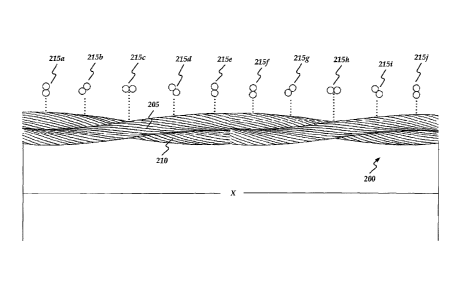
[052] FIG. 2 shows a VR cable 200 consistent with embodiments of
the invention. As shown in Fig. 2, VR cable 200 may comprise a first
conductor 205 and a second conductor 210 twisted around one another.
Cable 200 may have a lay length X. Lay length X may be constant over a
unit length of VR cable 200 or may vary over a unit length of VR cable 200.
For example, lay length X may vary at a constant rate between two feet and
four feet for every fifty feet of VR cable 200. Moreover, lay length X may
vary at a non-constant rate. Elements 215a through 215j show cross
sections of VR cable 200 at their respective corresponding locations. For
example, between elements 215c and 215h, one twist of VR cable 200
corresponding to lay length X may occur. VR cable 200 may be used in any
power line. RUS BULLETIN 1724E-200, "DESIGN MANUAL FOR HIGH
-11 -
CA 02692403 2009-12-31
WO 2009/018052
PCT/US2008/070885
VOLTAGE TRANSMISSION LINES", published by the Electric Staff Division,
Rural Utilities Service, U.S. Department of Agriculture shows how power
lines may be designed and is incorporated herein by reference.
[053] Lay length X may be configured to cause a power line using
VR cable 200 to have a natural frequency not equal to an expected
excitation frequency for an environment in which the power line is
constructed. Moreover, the natural frequency may not only be unequal to
the expected excitation frequency, but the natural frequency may be made
sufficiently different than the expected excitation frequency by a
predetermined value. In other words, the difference between the natural
frequency and the expected excitation frequency may be different by a value
that may be predetermined. Furthermore, a power line using VR cable 200
with lay length X may be determined to have a natural frequency range.
Likewise, the expected excitation frequency for the environment in which the
power line is constructed may have a range. Consistent with embodiments
of the invention, lay length X may have a value configured to cause the
aforementioned natural frequency range and the aforementioned expected
excitation frequency range to not overlap or to have a buffer frequency range
between the aforementioned natural frequency range and the
aforementioned expected excitation frequency range.
[054] For example, a frequency of a resonant vibration mode for a
span in the power line may comprise the natural frequency. The natural
frequency may depend on conductor size (e.g. diameter, weight, ect.) and
wind velocity and is generally between 5 and 100 Hz for wind speeds within
the range of 0 to 15 miles per hour. The expected excitation frequency may
-12-
CA 02692403 2009-12-31
WO 2009/018052
PCT/US2008/070885
comprise the frequency of the forces (e.g. wind) acting upon the power line.
Consistent with embodiments of the invention, lay length X may be constant
over a unit length of VR cable 200 or may vary over a unit length of VR cable
200. Lay length X may be selected to cause the power line to have a natural
frequency not equal to the expected excitation frequency for the environment
in which the power line is constructed. In this way, because the natural
frequency may not be equal to the expected excitation frequency, wind
corresponding to the expected excitation frequency may: i) not be able to
cause a vibration phenomenon in VR cable 200 used in the power line or ii)
may only cause a minimal vibration phenomenon in VR cable 200 that may
not damage the power line.
[055] In addition, lay length X may be configured to cause a power
line using VR cable 200 to provide a dampening effect to the power line
using VR cable 200 to vibration phenomenon caused at the expected
excitation frequency for an environment in which the power line is
constructed. Consistent with embodiments of the invention, lay length X
may be selected to cause VR cable 200 to be less "excitable" by winds
having a frequency and speeds expected to blow on VR cable 200 used in
the power line. In other words, "excitation characteristics" for VR cable 200
may be selected in such a way that energy from wind may be dampened
even when the natural frequency range for the power line may overlap the
expected excitation frequency range of the power line's expected
environment. The excitation characteristics may be selected to cause the
aforementioned dampening effect by selecting a particular lay length X or by
varying the lay length over a unit length of VR cable 200. For example, lay
-13-
CA 02692403 2009-12-31
WO 2009/018052
PCT/US2008/070885
length X may be selected to increase damping in VR cable 200 to dampen
vibrations that may develop before the vibrations produce damage to VR
cable 200 used in the power line.
[056] Consistent with embodiments of the invention, the lay length
may be optimized. For example, the lay length may be optimized in order to
have a range in a level of tightness between first conductor 205 and second
conductor 210. For example, if first conductor 205 and second conductor
210 are twisted around one another too loosely, relative movement between
first conductor 205 and second conductor 210 may be so great that bags
may occur in cable 200. However, if first conductor 205 and second
conductor 210 are twisted around one another too tightly, relative movement
between first conductor 205 and second conductor 210 may be so minimized
that the aeolian vibration dampening effect in cable 200 may be minimized to
an undesirable level.
[057] Consistent with embodiments of the invention, causing the
power line using the vibration resistant cable to have a natural frequency not
equal to an expected excitation frequency for an environment in which the
power line is constructed may occur when the power line is constructed to
the minimum design conditions associated with the National Electric Safety
Code (NESC) standards. (See TABLE 2.) Furthermore the aforementioned
bagging elimination and dampening effect for vibration phenomenon may
occur with the power lines built to National Electric Safety Code (NESC)
standards. Notwithstanding, the aforementioned desired attributes may
occur with power lines constructed to any standard and is not limited to the
NESC.
-14-
CA 02692403 2009-12-31
WO 2009/018052 PCT/US2008/070885
NESC LOADING DISTRICTS
District Design Radial Ice Wind
Constants
Temp. (P) Thickness Pressure (lbstft)
(inches) (PO)
Heavy Loading 0.0 0.5 4 0.30
Medium Loading 15 0.25 4 0.20
Light Loading 30 0 9 0.05
TABLE 2
[058] In cable 200 first conductor 205 and second conductor 210
may be viewed as two coil springs that may be right beside each other. As
cable 200 is strung in the air between power line structures, sheaves holding
cable 200 at the power line structures may have a tendency to grab one of
the conductors (e.g. first conductor 205 or second conductor 210.) Because
of friction between first conductor 205 and or second conductor 210 and the
stringing sheaves, there is push back. If first conductor 205 and second
conductor 210 are tight enough together as cable 200 tries to push back with
a compressive, spring force, this force pushes back and prevents bagging. If
may be assumed that friction between first conductor 205 and second
conductor 210 may be minimal (e.g. the conductors may be lubricated.)
-15-
CA 02692403 2009-12-31
WO 2009/018052
PCT/US2008/070885
[059] The following equations show the relationship between first
conductor 205 and second conductor 210 in cable 200:
K= d4,G
8D' N (1)
Where:
K is the spring rate
d is the diameter of the individual conductors
D is the distance between the two conductors
G is the modules of rigidity (a property like modulus of
elasticity)
N is the number of coils engaged or active coils
In the case that D and d are equal:
K=
8N (2)
Because (N)(LAY) = SPRING LENGTH,
N .SPRINGLENGTH
LAY (3)
Substituting (3) into (2)
K
(d)(G)(LAY)
=
(8)(SPRING LENGTH) (4)
Locking force = (K) (deflection), then
(d)(G)(LAY)(deflection)
Locking force -
(8)(SPRING LENGTH)
for a cable with conductor diameter = d1, Locking force is
for d = d1, Locking force = (d1)(G)(Lay1)(deflection)
Lay = Lay, (8)(Spring Length)
- 1 6 -
CA 02692403 2009-12-31
WO 2009/018052
PCT/US2008/070885
for a cable with conductor diameter = d2, Locking force is
for d = d2, Locking force = (d 2)(G)(Lay2)(deflection)
Lay = Lay2 (8)(Spring Length)
For the same locking force for cable constructions with di and d2. Two
different cables:
d 1G Lay, deflection = d 2G Lay2 deflection
8 Spring Length 8 Spring Length (5)
Now, setting (spring lengths) and (deflections) same for both cables,
equation (5) reduces to:
Lay 1 __ d2
Lay 2 di
[060] As shown above, the change in "lay" to achieve the same
locking force with the same deflection within the same active length of cable
may be linear with the change in diameter "d". This analysis neglects friction
in the model and assumes well lubricated conductors. Consequently, lay
length changing with diameter of individual conductor element can create a
"locking force" to prevent relative conductor sliding or movement. Movement
prevention may stop bags or loops from forming while, for example, making,
installing, or using cable 200. A linear relationship based on the above
formulas to describe the optimal lay of the cable which may prevent bags or
loops, may be given as:
Lay = cid -Fc2,
-17-
CA 02692403 2009-12-31
WO 2009/018052
PCT/US2008/070885
where d is the conductor diameter and c1 and c2 are
constants that can be chosen to achieve the desired locking
effect while still providing enough relative movement in the
cable for effective Aeolian vibration dampening.
As described above, the locking force may minimize or prevent conductor
movement as described by the above equations that relate to, for example,
compression springs. Because first conductor 205 and second conductor
210 become more spring-like the shorter the lay length becomes, the spring
forces in first conductor 205 and second conductor 210 tend to prevent
relative movement of first conductor 205 and second conductor 210. In
other words, the shorter the lay length becomes, the more resistant first
conductor 205 and second conductor 210 becomes to being either stretched
or compressed. For example, the lay length of VR cable 200 may be
configured to cause a locking force between first conductor 205 and second
conductor 210 configured to prevent relative movement of first conductor
205 and second conductor 210 that would result in bags in VR cable 200 if
the lay length were of a conventional length. The lay length may be further
configured to reduce a drag force when wind blows across VR cable 200
when a component of the wind, for example, is in a perpendicular direction to
an axis of VR cable 200. For example, the drag force may be reduced by
2`)/0 to 3%.
[061] FIG. 3A through FIG. 28 illustrate an operational example of
cable 200 that may show the effect of lay length on the stability of cable 200
consistent with embodiments of the present invention. This operational
example compares shorter lay VR cables or varying lay VR cables to
-18-
CA 02692403 2009-12-31
WO 2009/018052
PCT/US2008/070885
conventional long lay cable. Consistent with embodiments of the invention,
a reduction in drag coefficient with shorter lay lengths may be obtained as
compared to conventional long lay cables. Consequently, consistent with
embodiments of the invention, energy transferred into cable 200 may be
reduced, which may reduce the likelihood of galloping or vibration, for
example. The same results may be applicable to iced cables as well.
[062] As illustrated in FIG. 3A through FIG. 28, cables of varying lay
lengths may be analyzed using Computational Fluid Dynamics (CFD)
processes. Lift, drag, and moment on cables of fixed overall length (9 ft),
but
varying lay lengths may be examined. Vortex shedding behavior is also
examined. Also, the effect of lay on the aerodynamic behavior of the cables
is assessed. FIGs. 3A and 3B illustrate a "swallow" VR cable. As shown in
FIG. 3B, the cable comprises two individual conductors twisted together.
Each individual conductors comprises of a total of seven strands, six 0.0937"
Al strands and one 0.0937" steel strand (i.e. core.) The two conductors
twisted together result in a cross-section of the VR cable as shown in FIG.
3B.
[063] FIGs. 4A through 5B illustrate the VR cable's geometry. A
three-dimensional 9 ft. section is analyzed with respect to FIGs. 5A through
28. FIG. 4A shows a 3 ft. lay length, FIG. 4B shows a 9 ft. lay length, and
FIG. 4C shows a combination 6 ft. and 3 ft. lay length. FIGs. 5A and 5B
show a model depicting a mesh. FIG. 5A shows an overall mesh and FIG.
5B shows a close-up cable and mesh. In the flow model of the VR cable, a
three-dimensional 9 ft. section is analyzed. FIG. 6A is a key for the
-19-
CA 02692403 2009-12-31
WO 2009/018052
PCT/US2008/070885
directions. FIG. 6B shows the directions of the simulated unsteady flow
behavior of air at 25 mph over the VR cable.
[064] Flow behavior may be analyzed by examining the behavior on
planes (e.g. plane 1, plane 2, plane 2) of the VR lay configuration (geometry)
of FIG. 4A as shown in FIG. 7. FIGs. 8A, 8B, and 8C show flow velocity of
the 3 ft. lay VR cable at plane 1, plane 2, and plane 3 respectively. FIGs.
9A, 9B, and 90 show pressure of the 3 ft. lay VR cable at plane 1, plane 2,
and plane 3 respectively. FIGs. 10A, 10B, and 10C show flow velocity at
various times of the 3 ft. lay VR cable at plane 2. Velocity (m/s) on plane 2,
as shown in FIGs. 10A, 10B, and 100, at various time-instants indicates the
time-dependent (e.g. chaotic) nature of flow behavior. FIGs. 11A, 11B, and
110 show flow pressure at various times of the 3 ft. lay VR cable at plane 2.
Pressure (Pa) on plane 2 at various time-instants indicates, as shown in
FIGs. 11A, 11B, and 110, the time-dependent nature of flow behavior. FIGs.
12A, 12B, and 120 show forces on the 3 ft. lay VR cable at plane 1, plane 2,
and plane 3 respectively. To summarize the drag and lift of the VR lay
configuration (geometry) of FIG. 4A (e.g. the 3 ft. lay), CFD computed an
average drag force on the 9 ft. cable (3 ft. lay), for example, is 1.92 N. The
CFD computed movement and lift force on the 9 ft. cable (3 ft. lay), for
example, are negligible.
[065] Flow behavior may be analyzed by examining the behavior on
planes (e.g. plane 1, plane 2, plane 2) of the VR lay configuration (geometry)
of FIG. 4B as shown in FIG. 7. FIGs. 13A, 13B, and 130 show flow velocity
of the 9 ft. lay VR cable at plane 1, plane 2, and plane 3 respectively. FIGs.
14A, 14B, and 14C show pressure of the 9 ft. lay VR cable at plane 1, plane
- 20 -
CA 02692403 2009-12-31
WO 2009/018052
PCT/US2008/070885
2, and plane 3 respectively. FIGs. 15A, 15B, and 150 show flow velocity at
various times of the 9 ft. lay VR cable at plane 2. Velocity (m/s) on plane 2,
as shown in FIGs. 15A, 15B, and 150, at various time-instants indicates the
time-dependent (e.g. chaotic) nature of flow behavior. FIGs. 16A, 16B, and
160 show flow pressure at various times of the 9 ft. lay VR cable at plane 2.
Pressure (Pa) on plane 2 at various time-instants indicates, as shown in
FIGs. 16A, 16B, and 16C, the time-dependent nature of flow behavior. FIGs.
17A, 17B, and 17C show forces on the 9 ft. lay VR cable at plane 1, plane 2,
and plane 3 respectively. To summarize the drag and lift of the VR lay
configuration (geometry) of FIG. 4B (e.g. the 9 ft. lay), CFD computed an
average drag force on the 9 ft. cable (9 ft. lay), for example, is 2.011 N.
The
CFD computed movement and lift force on the 9 ft. cable (9 ft. lay), for
example, are negligible.
[066] Flow behavior may be analyzed by examining the behavior on
planes (e.g. plane 1, plane 2, plane 2) of the VR lay configuration (geometry)
of FIG. 4C as shown in FIG. 7. FIGs. 18A, 18B, and 180 show flow velocity
of the 6 ft.-3ft. combination lay VR cable at plane 1, plane 2, and plane 3
respectively. FIGs. 19A, 19B, and 190 show pressure of the 6 ft.-3ft.
combination lay VR cable at plane 1, plane 2, and plane 3 respectively.
FIGs. 20A, 20B, and 200 show flow velocity at various times of the 6 ft.-3ft.
combination lay VR cable at plane 2. Velocity (m/s) on plane 2, as shown in
FIGs. 20A, 20B, and 200, at various time-instants indicates the time-
dependent (e.g. chaotic) nature of flow behavior. FIGs. 21A, 21B, and 12C
show flow pressure at various times of the 6 ft.-3ft. combination lay VR cable
at plane 2. Pressure (Pa) on plane 2 at various time-instants indicates, as
- 21 -
CA 02692403 2009-12-31
WO 2009/018052 PCT/US2008/070885
shown in FIGs. 21A, 21B, and 21C, the time-dependent nature of flow
behavior. FIGs. 22A, 22B, and 22C show forces on the 6 ft.-3ft. combination
lay VR cable at plane 1, plane 2, and plane 3 respectively. To summarize
the drag and lift of the VR lay configuration (geometry) of FIG. 40 (e.g. the
6
ft.-3ft. combination lay), CFD computed an average drag force on the 9 ft.
cable (6 ft.-3ft. combination lay), for example, is 1.968 N. The CFD
computed movement and lift force on the 9 ft. cable (6 ft.-3ft. combination
lay), for example, are negligible.
[067] TABLE 3 below summarizes the above analysis on the VR
cable consistent with embodiments of the invention. As indicated in TABLE
3, the analysis indicates that the lifting force and torsional moment on the
VR
cable may be negligible. The lay length may be no affect on this force and
the moment. The lay length may have an effect on the drag force over the
VR cable. A general trend where the drag force decreases with a decrease
in lay length may be observed.
Cable Layout Force (N) over 9 Comments
ft
section of cable
3 ft. lay cable 1.91 Lowest force of all cables
analyzed
6 ft. and 3 ft. combination 1.97
lay
9 ft. lay cable 2.01 Highest force of all 3 lay
lengths
TABLE 3
[068] A distinct vortex shedding frequency may not observed for the
VR cable as the angle of attack of the cable cross-section continuously
- 22 -
CA 02692403 2009-12-31
WO 2009/018052
PCT/US2008/070885
changes along the length of the VR cable. The forces computed using a 2d
analysis compare reasonably with the 3d predictions. The drag force
predicted using 3d simulations is lower than that predicted using 2d
simulations. As described below, the mechanism that leads to a reduction in
the drag over the VR cable is explored by examining the details of the flow
behavior over the cable.
[069] FIGs. 23 and 24 show an examination of detailed flow
behavior. FIG. 23 shows the detailed examination for the 9 ft. lay VR cable
(e.g. FIG. 4B) and FIG. 24 shows the detailed examination for a 3 ft. lay VR
cable (e.g. FIG. 4A.) In FIGs. 23 and 24, span-wise flow is observed, which
may lead to a reduction in the drag force.
[070] Next, an examination of a detailed flow behavior for a 1 ft. lay
VR cable will be shown. FIG. 25 illustrates a 3 ft. long section of a 1 ft.
lay
VR cable. To gain greater confidence in the trends observed using 3 ft., 9
ft., and 3 ft. ¨ 6 ft. lay, a 1 ft. lay length cable is investigated. It is
anticipated
that a 1 ft. lay length cable will show more dramatic results as compared to
the other lay lengths. FIG. 26A shows flow pressure at a times of the 1 ft.
lay VR cable at mid span plane. FIG. 26B is a corresponding force plot with
respect to time. According to the examination, the drag force on the 3 ft.
section of 1 ft. lay length cable is 0.63N, this force is scaled to obtain the
drag force on a 9 ft. cable. The force on a 9 ft. long, 1 ft. lay length cable
is
(3*.63) 1.89N. The lift force and moment on the cable are negligible. FIGs.
27A and 27B show the examination of detailed flow behavior for a 3 ft. lay
VR cable. FIG. 27A shows velocity vectors plotted near the surface of the 3
ft. lay VR cable. FIG. 27B shows velocity vectors with span-wise speed.
- 23 -
CA 02692403 2009-12-31
WO 2009/018052 PCT/US2008/070885
[071] As shown in TABLE 4 below, the CFD analysis predicts that
the lifting force and torsional moment on the VR cable may be negligible.
The lay length may have no affect on the lift force and the moment. The lay
length may have an effect on the drag force over the VR cable. A trend
where the drag force decreases with a decrease in lay length may be
observed as shown in TABLE 4.
Cable Layout Force (N) over 9 ft Comments
section of cable
Lowest force of all cables
1 ft. lay cable 1.89 analyzed (6% reduction in
drag as compared to 9 ft.
lay cable)
3 ft. lay cable 1.91 5% reduction in drag as
compared to 9 ft. lay cable
6 ft. and 3 ft. combination 1.97 2% reduction in drag as
lay compared to 9 ft. lay cable
9 ft. lay cable 2.01 Highest force of all 4 lay
lengths
TABLE 4
[072] Drag reduction over aerodynamic bodies may not easily
achieved. A drag reduction of even 1-2% for aerodynamic shapes may be
considered good. A decrease in the net force acting on the VR cable may
be observed with a decrease in lay length. A reduction in the net force on
the VR cable and no change in the moment may result in a more stable
cable. A close examination of the flow behavior may indicate span-wise flow
along the VR cable. As illustrated in FIG. 28, the span-wise flow may be
directed towards the cross-section that subtends the smallest area to the
incoming flow. The span-wise flow for the 1 ft. lay VR cable may be higher
-24-
CA 02692403 2009-12-31
WO 2009/018052
PCT/US2008/070885
than that for the 3 ft. lay VR cable, which is higher than that for the 9 ft.
lay
VR cable. A trend indicating a decrease in drag with decreased lay length
may be observed. A preliminary assessment of the flow behavior may
indicate that span-wise flow may be responsible for a reduction in the drag
force. This behavior may be similar to that observed for a swept aircraft
wing. A backward sweep of the wing induces span-wise flow and a
reduction in the drag and lift forces. VR cable lay induces twisting, which in
turn may cause a span-wise flow to occur and hence a change in the drag
force. Consequently, the above data indicates that the drag force over the
VR cable may be reduced by reducing the lay length of the VR cable.
[073] While certain embodiments of the invention have been
described, other embodiments may exist. Further, the disclosed methods'
stages may be modified in any manner, including by reordering stages
and/or inserting or deleting stages, without departing from the invention.
While the specification includes examples, the invention's scope is indicated
by the following claims. Furthermore, while the specification has been
described in language specific to structural features and/or methodological
acts, the claims are not limited to the features or acts described above.
Rather, the specific features and acts described above are disclosed as
example for embodiments of the invention.
- 25 -