Note: Descriptions are shown in the official language in which they were submitted.
CA 02692410 2016-04-20
- 1 -
Guide plate for a system for fastening a rail to a
substrate, and a system comprising a guide plate of this
type
The invention relates to a guide plate for a system for
fastening a rail to a substrate on which there is provided,
laterally of the railway track, a shoulder which absorbs
the forces which are produced when a rail vehicle travels
on the rail. The guide plate has in this case an underside
which is associated with the substrate and an upper side
which is exposed in the installation position, is arranged
remote from the underside and on which it is possible to
support a spring element provided for applying resiliently
elastic holding-down forces to the rail to be fastened.
In addition, the invention relates to a system for
fastening a rail to a substrate on which there is provided,
laterally of the railway track, a shoulder. The system
according to the invention comprises in this case a spring
element for exerting an elastic holding-down force on the
rail, a guide plate for guiding the spring element and a
tensioning element for bracing the spring element against
the substrate.
In systems of this type, the object of the guide plates is,
on the one hand, to absorb the forces occurring when the
rail is travelled on and are directed transversely to the
rail longitudinal direction and to transmit them to the
shoulder which is securely fixed to the substrate. On the
other hand, the guide plates serve as a rest for a
respective spring element which exerts, when a rail
fastening system equipped with the guide plate is fully
CA 02692410 2016-04-06
- 2 -
,
installed, the required elastic holding-down force on the
rail foot.
Guide plates known by the name "angled guide plates", such
as for example that offered by the Applicant under the
designation "W14.1", have a basic shape which, viewed from
above, is rectangular and elongate and on one longitudinal
side of which, associated with the rail, a guide surface is
designed. When the guide plate is fully installed, this
guide surface abuts fully against the rail foot and fixes
the position of the rail in the transverse direction. In
this case, the known angled guide plate has a through-
opening which is oriented roughly centrally, extends from
its upper side down to its underside and through which it
is possible to pass during installation a fastening screw
which braces the guide plate, with the spring element
arranged thereon, against the substrate.
In addition to the prior art commented on hereinbefore,
DE 41 01 198 Cl describes a guide plate intended for
fastening a rail by means of a w-shaped tensioning clamp.
Depressions, in which the central part, which is bent in a
U-shaped manner, of the tensioning clamp is positioned after
installation, are provided in the known guide plate. In
addition, the known angled guide plate has a flute extending
parallel to the rail in the installation position. The
outwardly leading portions of the tensioning clamp are
supported in this flute after installation, longitudinally
and transversely to the rail to be fastened in each case.
The known guide plates described hereinbefore presuppose the
design of a shoulder in or on the respective substrate, on
which shoulder the guide plate rests when installed.
CA 02692410 2016-04-06
- 3 -
Conventionally, this shoulder is formed by a step which is
moulded onto the substrate and against which the guide plate
rests with its side remote from the rail when installed.
Another possibility of supporting a rail is described in
US 4,313,563. In this system for fastening a rail, which is
also known by the name "SafelokT", a shoulder piece, which
is made from cast iron material, is cast into the fixed
substrate which is generally formed from a concrete sleeper.
This shoulder piece has, at its portion resting
freely on the surface of the fixed substrate, a receptacle,
the opening of which is arranged on the side of the step
that is remote from the rail to be fastened.
In the Safelok system, a spring clip, which is shaped
integrally from flat steel and has a crosspiece from which
two spring arms running substantially parallel to each other
emanate, engages into the recess of the shoulder.
These spring arms are guided, viewed from the side, starting
from the crosspiece positioned in the recess of the shoulder
piece, in a large arc in the direction of the rail to be
fastened, the spring arms ending, when untensioned, in a
position arranged below the crosspiece. When installed, the
spring arms press in a correspondingly pretensioned manner
with their free ends onto the foot of the rail to be
fastened, the upper side of which foot is located
substantially at the same level as the receptacle of the
shoulder.
The advantage of the Safelok system consists in the fact
that it can be installed using a specially shaped tool. In
practice, it has been found that, under the high loads
resulting from heavy-load or high-speed traffic, force and
CA 02692410 2010-02-09
- 4 -
spring excursion losses, as a result of which the spring
force is greatly reduced, occur in the spring clips used in
these systems within a short period of use. It can also
occur that the spring clips are deformed during
installation to the extent that they lose the spring
properties required for properly holding down the rail. As
a consequence of the decreasing spring action, the
resistance to sliding-through of the rail foot in a
direction directed to transversely to the longitudinal
extension of the rail is also reduced.
A further disadvantage of the known the Safelok system,
which has a particularly negative effect specifically in
high-speed and heavy-load traffic, consists in the fact
that in this system the rail is not protected against
tilting which can occur, in particular, when high
transverse forces occur. Finally, in the known Safelok
system, the requirement for maximum possible insulation of
the rail in relation to the substrate supporting it may be
fulfilled only in a highly complex manner.
Against this background, the object of the invention was to
provide a component allowing the requirements of modern
rail travel operation to be met even in fastening systems
of the type in which the forces occurring during travel
operation are dissipated via a shoulder present on or in
the fixed substrate.
In this case, the component to be provided by the invention
should in particular be suitable to changeover in a simple
manner existing fastening systems of the Safelok type in
such a way that they reliably withstand the loads occurring
in practice over a sufficiently long operating period.
SI/cs 081823W0
2 February 2010
CA 02692410 2016-04-06
- 5
The invention also seeks to provide a system for fastening a
rail in which the disadvantages commented on hereinbefore no
longer exist.
Certain exemplary embodiments can provide a guide plate for
a system for fastening a rail to a substrate on which there
is provided, laterally of a railway track, a shoulder which
absorbs the forces occurring when the rail is travelled on
by a rail vehicle, the guide plate having an underside which
is associated with the substrate and an upper side which is
exposed in an installation position, is remote from the
underside and on which is supportable a spring element
provided for applying resiliently elastic holding-down
forces to the rail to be fastened, wherein there is shaped
into the underside of the guide plate a recess, the
dimensions of which are adapted to the dimensions of the
shoulder in such a way that the shoulder engages freely into
the recess in the installation position of the guide plate
and in that at least one reinforcing rib, which protrudes in
the direction of an opening of the recess over a height
which is less than a height of the recess, is disposed on a
roof surface of the recess that opposes an opening of the
recess.
Certain exemplary embodiments can provide a system for
fastening a rail to a substrate on which there is provided,
laterally of a railway track, a shoulder, comprising a
spring element for exerting an elastic holding-down force on
the rail, a guide plate for guiding the spring element and a
tensioning element for bracing the spring element against
the substrate, wherein the guide plate is designed as
described above.
CA 02692410 2016-04-06
A guide plate according to the invention for a system for
fastening a rail to a substrate on which there is provided,
laterally of the railway track, a shoulder which absorbs the
forces occurring when the rail is travelled on by a rail
vehicle, has in accordance with the prior art commented on
at the outset an underside which is associated with the
substrate and an upper side which is exposed in the
installation position and is remote from the underside. On
the upper side of the guide plate, it is in this case also
possible to support, as in the prior art discussed at the
outset, a spring element provided for applying resiliently
elastic holding-down forces to the rail to be fastened.
According to the invention, there is now shaped into the
underside of the guide plate a recess, the dimensions of
CA 02692410 2010-02-09
- 6 -
which are adapted to the dimensions of the shoulder in such
a way that the shoulder engages freely into the recess in
the installation position of the guide plate.
In addition, at least one reinforcing rib, which protrudes
in the direction of the opening of the recess over a height
which is less than the height of the recess, is designed at
least on the roof surface of the recess that opposes the
opening of the recess.
Through the recess shaped into the guide plate according to
the invention from its underside, the guide plate can be
placed onto the shoulder which is in each case present on
the fixed substrate. The shoulder is in this case received
by the recess in such a way that the guide plate itself is
supported, with its standing surface remaining at the
underside, on the fixed substrate.
If appropriate, one or more intermediate layers can in this
case be provided between the underside of the guide plate
and the .fixed substrate in order, for example, to achieve a
defined flexibility and a specific wear behaviour of the
fastening point formed by the guide plate and the "spring
element" and "tensioning element" components interacting
therewith.
As a standard feature, the at least one reinforcing rib
which is, in accordance with the invention, present in the
receptacle, at the roof surface thereof, is dimensioned in
such a way that, under optimum conditions in the attached,
still-force-free state, there is a certain distance between
the underside of said rib that is associated with the
shoulder and the surface of the shoulder that is in each
case associated therewith. If subsequently the spring
element positioned on the guide plate is braced, the guide
Si/cs 081823W0
2 February 2010
CA 02692410 2010-02-09
- 7 -
plate can undergo deformation until the rib is positioned
on the shoulder and the roof portion of the guide plate,
which roof portion covers the recess and carries the spring
element, is supported on the shoulder. This reliably
prevents excessive bending of the guide plate.
Should the reinforcing rib become fractured over the course
of the bracing of the spring element, then this does not
detract from the supporting function of said reinforcing
rib, as in this case the guide plate is supported on the
shoulder via the fragments remaining between the shoulder
and the roof surface of the guide plate.
As a fracture of the reinforcing ribs present in each case
is consciously allowed for, the reinforcing ribs are
generally so narrow in their design as to be able to absorb
only low transverse forces. Thus, the thickness of the
reinforcing ribs is typically less than one fifteenth, in
particular less than one twentieth, of the width of the
guide plate as measured in the longitudinal direction of
the rail to be fastened. Thus, in practice, the ribs are
approx. 5 mm wide, whereas the guide plate is approx. 115
mm wide as measured in the rail longitudinal direction.
If the shoulder is not optimally positioned, because it for
example juts out too high above the substrate, is
positioned too deeply or is oriented obliquely, the
fracture of the reinforcing rib is even brought about in a
targeted manner during installation. This allows the free
volume present in the receptacle to automatically adapt to
the requirements resulting from the respective orientation
and positioning of the shoulder without the installation
process having to be interrupted for this purpose. This
allows the guide plate to be supported securely on the
SI/cs 081823W0
2 February 2010
CA 02692410 2010-02-09
- 8 -
shoulder present in or on the fixed substrate even when the
shoulder is positioned imprecisely.
In this way, guide plates according to the invention allow,
in a particularly lightweight design, the spring elements
positioned thereon to be pretensioned with high forces
without there being in this case the risk of a fracture of
the guide plate. In this regard, a guide plate designed in
accordance with the invention is particularly suitable for
changing over existing fastening systems in which a
corresponding shoulder is already provided in or on the
respective fixed substrate. That is to say, as a result of
the fact that the invention uses this shoulder to support
the guide plate according to the invention and a guide
plate according to the invention is in each case designed
in such a way that its recess automatically adapts to the
shape and position of the shoulder in question, the
changing over can be carried out in a manner which is as
simple as is conceivably possible and at accordingly
minimised costs.
Two or more reinforcing ribs designed in the manner
according to the invention can be provided in the recess of
a guide plate according to the invention if, for example,
this increases the secureness of the supporting and
stiffening of the roof portion of the spring element, which
roof portion covers the recess and carries the spring
element when installed.
A system according to the invention for fastening a rail to
a substrate on which there is provided, laterally of the
railway track, a shoulder, comprises in accordance with the
prior art specified at the outset a spring element for
exerting an elastic holding-down force on the rail, a guide
SI/cs 081823W0
2 February 2010
CA 02692410 2010-02-09
- 9 -
plate for guiding the spring element and a tensioning
element for bracing the spring element against the
substrate. The advantages of the configuration according to
the invention of a guide plate, as summarised in a general
manner hereinbefore, may be utilised in a system of this
type in that its guide plate is designed in the manner
according to the invention.
According to one embodiment of the invention, the guide
plate has, at its front side associated with the rail to be
fastened, a planar abutment surface for the rail foot. Via
this abutment surface, the rail is supported against the
transverse forces occurring when the rail is travelled on.
Advantageously, the at least one reinforcing rib provided
in the receptacle of a guide plate according to the
invention is oriented transversely to the abutment surface
of the guide plate. In this way, the reinforcing rib not
only supports the roof portion of the guide plate, which
roof portion covers the receptacle and carries the spring
element on its upper side, but stiffens the guide plate
even in a direction oriented transversely to the
longitudinal extension of the rail to be installed.
Accordingly, despite the comparatively large-volume recess
intended for receiving the shoulder, the guide plate is
able to reliably absorb high transverse forces in the
installation position.
Optimum supporting of the guide plate while at the same
time effectively protecting the shoulder may be achieved in
that the recess shaped into its underside is delimited, at
its front associated with the rail and its back opposing
the front and also the sides extending between the front
and the back, in each case by a wall of the guide plate.
SI/cs 081823W0
2 February 2010
CA 02692410 2010-02-09
- 10 -
This complete bounding of the recess by walls of the guide
plate has a particularly positive effect when the shoulder
is made from a material at a high risk of corrosion, for
example cast iron or cast steel. In this embodiment of the
invention, the guide plate protects shoulders of this type
against contact with corrosive media. Should water or other
liquids nevertheless accumulate in the region of the
recess, then, for discharging into the back wall associated
with the back of the recess or the lateral walls, channels,
leading from the recess into the environment, can be
provided for draining any liquid collecting in the recess
of the guide plate. The channels can in this case be formed
in a simple manner in that they are open in the direction
of the underside of the guide plate.
In particular in applications in which the shoulder
provided in or on the fixed substrate is suitable for being
connected to a tensioning means required for tensioning the
respective spring element, such as is the case for example
in the shoulders of the Safelok system that are cast into
the fixed substrate, it can be expedient if there is shaped
into the guide plate a through-opening which leads from its
upper side into the recess and through which the
respectively required tensioning element can be inserted
during installation for tensioning the spring element. In
order to compensate for the weakening of the roof portion
of the guide plate such as is caused by this opening, a
respective reinforcing rib designed in the manner according
to the invention can be arranged within the recess at two
opposing sides of the through-opening. This arrangement of
the reinforcing ribs provided in accordance with the
invention allows the material thicknesses in the region of
SI/cs 081823M0
2 February 2010
CA 02692410 2010-02-09
- 11 -
the roof portion of the guide plate to be reduced to a
minimum despite the through-opening shaped therein.
On account of the stiffening and supporting of the guide
plate as achieved by the ribs according to the invention,
it is readily possible to make the guide plate in one piece
from a plastics material. Making the guide plate from
plastic not only has the advantage of a particularly low
weight and simple manufacturability, but also offers good
electrical insulation without this requiring additional
measures. Minimum walls thicknesses with at the same time
optimised stability under load are in this case obtained
when the plastic is fibre-reinforced.
It is possible to further minimise the material thickness,
in particular in the region of the roof portion covering
the recess and carrying the spring element in the
installation position, in that at least one reinforcing rib
is designed even at the free upper side of the spring
element. For the advantageous orientation and configuration
of said reinforcing rib, the foregoing comments concerning
the reinforcing ribs provided in the recess of the guide
plate apply accordingly.
In addition, shaped elements, such as webs, depressions,
ribs and the like, can be provided at the upper side of the
guide plate according to the invention for laterally
guiding, in certain portions, the spring element to be
supported on the guide plate.
An embodiment of the invention that is particularly
advantageous for applications requiring high electrical
insulation of the rail consists in the fact that the guide
plate carries, at its front side associated with the rail
to be fastened, an insulator element which extends parallel
Slics 081823W0
2 February 2010
CA 02692410 2010-02-09
- 12 -
to the front side and is intended to rest during
installation on the foot of the rail to be fastened in such
a way that the spring element applying the holding-down
force acts on the rail via the insulator element. The fact
that the insulator element is securely connected to the
guide plate means that installation thereof is as simple as
is conceivably possible and may be managed in a
particularly reliable manner, including in particular with
the aid of automatically operating installation machines.
The secure connection between the guide plate and the
insulator element can in this case be established in that
the insulator element, as early as during the manufacturing
process itself, is integrally connected to the guide plate,
is adhesively bonded to the guide plate or attached to the
guide plate. In this case, the fact that a predetermined
breaking point is designed in the region of transition
between the insulator element and the guide plate means
that it is possible to ensure in a simple manner that the
arrangement according to the invention of the insulator
element does not restrict the holding-down force exerted by
the spring element on the rail in the installation
position. Thus, the insulator element purposefully breaks
away from the guide plate if a specific loading is exceeded
during tensioning of the spring element. The insulator
element is then freely movable and can readily follow the
movements of the rail and the spring element.
The shoulder present in or on the respective fixed
substrate may, in the manner according to the invention,
not only be used for supporting the guide plate itself, but
can also serve as an abutment for the tensioning element
used for tensioning the spring element. In order to allow
this, the tensioning element in question can have a
Si/cs 081823P0
2 February 2010
CA 02692410 2010-02-09
- 13 -
coupling portion for coupling in a form-fitting manner to
the shoulder provided on the substrate. With this coupling
portion, the tensioning element engages, for example, into
a corresponding receptacle of the shoulder or interacts
with a suitably shaped projection of the shoulder.
In order to ensure a defined flexibility of the fastening
point formed by the fastening system according to the
invention, the system according to the invention can
comprise an elastic intermediate layer on which the rail is
positioned when the system is fully installed. This
intermediate layer can be designed in such a way that it
extends, when the system is fully installed, below the rail
to be fastened in order to ensure a defined flexibility
even in the rail.
In order to provide protection against excessive abrasive
wear, it may be expedient, in particular in areas which are
subject to high dust or sand drift loading, if the system
according to the invention comprises an abrasion plate
which is positioned on the substrate when the system is
fully installed. All the other elements of the system
according to the invention are then positioned on this
abrasion plate which consists, for example, of a material
having high abrasion resistance.
The fixed substrate, on which the guide plate according to
the invention and the system according to the invention are
installed, is typically formed by a concrete slab or a
sleeper cast from concrete or a solid material having
comparable stability under load. Likewise, the sleeper can
be made from wood, plastic or steel.
The shoulder, on which the guide plate designed in
accordance with the invention rests, can be designed, as in
SLics 081823WO
2 February 2010
CA 02692410 2010-02-09
- 14 -
the Safelok system, as a shoulder piece which is positioned
securely in the substrate with a fastening portion, while
its shoulder portion protrudes freely beyond the surface of
the fixed substrate.
If a respective guide plate is associated with each
longitudinal side of the rail, the installation and the
holding of the guide plate can be made particularly simple
and secure in that the guide plates are integrally
connected to one another by a portion extending below the
rail in the installation position.
Furthermore, the system according to the invention can also
comprise a plate which is positioned on the substrate, on
which the shoulder is designed and on which the guide plate
is positioned when fully installed. Plates of this type,
which are ,referred to by experts also as "rib plates", are
widely used to simplify installation and to uniformly
distribute the forces occurring when the respective
fastening point is travelled over.
In cases in which the shoulder to be received by the
receptacle is formed in a particularly rugged or angular
manner, for example as a consequence of corrosion or other
wear in the region of its circumferential surfaces, it may
be expedient to separately protect against abrasive wear
the inner surface, facing the shoulder, of the longitudinal
side wall associated with the foot of the rail to be
fastened. This can be achieved by arranging at the inner
surface, remote from the abutment surface, of the
longitudinal side wall associated with the rail foot of the
rail to be fastened a protective element which protects
this inner surface from wear and is made of a material, the
wear resistance of which is greater than the wear
si/cs 081823W0
2 February 2010
CA 02692410 2010-02-09
- 15 -
resistance of the material from which the longitudinal side
wall in question is made. The object of the protective
element, which is designed in particular as an insert, is
to stiffen the relatively thin-walled abutment surface, so
that the material of the guide plate does not work its way
into the worn shoulder (anchor) of the original fastening.
The protective element in question can be incorporated, for
example in the form of an inlay which is connected to the
guide plate in a material-uniting or form-fitting manner,
directly into the longitudinal wall to be protected. A
particularly economical possibility of protection results
from the fact that the protective element is inserted, as a
separately prefabricated component, into the receptacle of
the guide plate in such a way that it abuts against the
longitudinal wall to be protected. The use of a separately
prefabricated protective element allows this element to be
inserted when the local conditions demand this. The
arrangement of a protective element protecting the
longitudinal side wall has proven particularly advantageous
when the guide plate is made from a plastic.
In order to protect even the roof surface of the receptacle
of the guide plate against abrasive wear, it may be
expedient to arrange there, too, a protective element of
the type described hereinbefore in relation to the
longitudinal side wall associated with the rail foot. With
regard to installation, manufacture and an optimised
protective effect that are as simple as possible, this can
be achieved in that the protective element has a portion
extending along the longitudinal side wall and at least one
further portion extending along the roof surface of the
recess.
SI/cs 081823W0
2 February 2010
CA 02692410 2010-02-09
- 16 -
The protective element may be made particularly
economically from steel sheet.
The invention will be commented on in greater detail
hereinafter based on drawings which illustrate an exemplary
embodiment and in which:
Fig. 1 is a schematic perspective view from below of a
guide plate;
Fig. 2 is a schematic perspective view from above of the
guide plate;
Fig. 3 is a schematic plan view of a rail fastening
system;
Fig. 4 is a schematic view of the rail fastening system
in a section along the sectional line A-A drawn in
Fig. 3;
Fig. 5 is a schematic perspective view of a tensioning
element inserted in the rail fastening system;
Fig. 6 is a schematic view from below of the guide plate
according to Fig. 1;
Fig. 7 is a schematic view of an alternative
configuration of a rail fastening system in a
section corresponding to Fig. 4; and
Fig. 8 is a schematic view from below of a guide plate
which is inserted in the rail fastening system
designed in accordance with Fig. 7 and has a
protective element inserted therein.
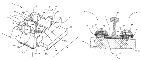
The guide plate 1, which has the basic shape of a cuboid
and is made in one piece from a fibre-reinforced plastic,
has an underside 2 and an upper side 3 which is remote from
SI/cs 081823W0
2 February 2010
CA 02692410 2010-02-09
- 17 -
the underside 2 and is exposed in the installation
position.
A recess 4, the opening 5 of which takes up the vast
majority of the underside 2, is shaped into the guide plate
1 from its underside 2. In this case, the recess 4 is
bounded by a first longitudinal side wall 6 associated with
the rail to be installed, a rearward second longitudinal
side wall 7 arranged opposite thereto, a first narrow side
wall 8 extending on one narrow side of the guide plate 1
and a second narrow side wall 9 which is arranged opposite
thereto and is associated with the other narrow side of the
guide plate 1.
The surfaces of the longitudinal sides 6, 7 and the narrow
sides 8, 9 that are associated with the underside 2 form a
standing surface 10 with which the guide plate 1 is
positioned on the respective substrate in the installation
position. In this case, a respective corner step 11, 12
protruding in the direction of the recess 4 is shaped in
the corner regions between the first longitudinal side 6
and the narrow side walls 8, 9, so that an extended region
of the standing surfaces 10 is provided there. At the same
time, the wall thickness of the second longitudinal side 7
is greater than that of the first longitudinal side 6, so
that secure supporting of the guide plate is ensured even
in the region of the second longitudinal side 7.
The first longitudinal side 6 is associated with the foot
13 of the rail 14 to be installed. For this purpose, a
planar abutment surface 15, which extends over the width B
of the guide plate 1 and encloses a right angle with the
standing surface 10, is designed at the side thereof
associated with the rail foot 13. In the installation
SI/cs 081823W0
2 February 2010
CA 02692410 2010-02-09
- 18 -
position, the rail foot 13 rests on the abutment surface
15.
A respective channel 16, 17 is shaped into the narrow side
walls 8, 9, which channels 16, 17 lead from the recess 4 to
the environment U and are designed so as to be open toward
the standing surface 10 in the manner of recesses.
Likewise, channels 18, 19, 20, which are arranged at
uniform distances from one another and via which liquid
(rainwater) can also flow away in the installation position
of the guide plate, are shaped into the second longitudinal
wall 7.
A through-opening 22, leading from the upper side 3 of the
guide plate 1 into the recess 4, is shaped into the roof
portion 21 of the guide plate 1 at a central location. The
through-opening 22 has in this case a shape which is
stretched in a groove-like manner and the longitudinal axis
of which is oriented transversely to the abutment surface
15.
Two reinforcing ribs 23, 24, which are each oriented
transversely to the abutment surface 15, emanate from the
roof surface 25 formed by the underside of the roof portion
21 of the guide plate 1 and each extend between the
longitudinal side walls 6, 7 of the guide plate 1, are
provided in the recess 4. One reinforcing rib 23 is in this
case arranged in close proximity to one longitudinal side
of the through-opening 22, whereas the other reinforcing
rib 24 is positioned immediately adjacently to the other
longitudinal side of the through-opening 22.
The reinforcing ribs 23, 24 each have a portion 23a, 24a
which is connected to the rearward longitudinal wail 7 and
extends approximately over the entire height H of the
si/cs 081823W0
2 February 2010
CA 02692410 2010-02-09
- 19 -
recess 4. However, said portion ends in this case at a
short distance H1 from the standing surface 10, so that, in
this region too, the reinforcing ribs 23, 24 do not touch
the substrate on which the guide plate 1 is positioned
during practical use.
Starting from the longitudinal wall 7, the respective
portion 23a, 24a of the reinforcing ribs 23, 24 extends in
each case over roughly one third of the depth T of the
recess 4 and merges there in each case with a second
portion 23b, 24b which has a much lower height H2 than in
the region of its respective portion 23a, 24a. The narrow
side 23c, 24c of the portion 23a, 24a, which narrow side
leads to the second portion 23b, 24b, is in this case
oriented at right angles to the standing surface 10 and
parallel to the abutment surface 15.
The respective portion 23b, 24b extends in each case up to
the longitudinal side wall 6. Within the recess 4, a free
spatial volume, the shape and external dimensions of which
are configured with a specific oversize in such a way that
a shoulder 26, which is provided on the fixed substrate U
to which the rail 14 is to be fastened, can be securely
received in this free volume when this shoulder 26 is
optimally oriented, is in this way delimited between the
longitudinal side wall 6, the narrow sides 23c, 24c
associated therewith of the portions 23a, 24a and the
narrow side walls 8, 9. The dimensions of the height H2 of
the portions 23b, 24b of the reinforcing ribs 23, 24 are in
this case such that, when the guide plate 1 is not
subjected to any loads, the underside 23d, 24d of the
portions 23b, 24b and the lateral surface 23c, 24c of the
portions 23a, 24a are arranged at a short distance above or
laterally of the shoulder 26.
s'ics 081823410
2 February 2010
CA 02692410 2010-02-09
- 20 -
As a result of the fact that the volume of the recess 4
that is present between the portions 23a, 24a or between
the respective narrow side wall 8, 9 and the associated
portion 23a, 24a of the reinforcing ribs 23, 24 is also
added, the guide plate 1 has a minimised mass and an
accordingly minimised weight.
Two flutes 28, 29, of which one emanates from the side of
the guide plate 1 that is associated with the narrow side
wall 8 and the other emanates from the side of the guide
plate 1 that is associated with the narrow side wall 9, are
shaped on the free upper side 3 of the guide plate 1,
adjoining the edge associated with the rearward
longitudinal side wall 7. The flutes 28, 29 are separated
by a reinforcing rib 30 which is oriented, based on the
abutment surface 15, centrally and transversely thereto.
In addition, two guide ribs 31, 32, of which one extends
parallel to one longitudinal side and the other extends
parallel to the other longitudinal side of the through-
opening 22, are provided on the upper side 3 of the guide
plate 1. Support portions 33, 34, extending parallel to the
abutment surface 15, support the guide ribs 31, 32 on their
side associated with the narrow side wall 8 and the narrow
side wall 9 respectively, whereas their lateral surface
associated with the through-opening 22 merges, in each case
in a chamfer, with the surface surrounding the through-
opening 22. When installed, the guide ribs 31, 32 support
the central loop 35 of a w-shaped spring element 36 which,
with its spring arms 37, 38, exerts in a manner known per
se on the rail foot the spring forces required for holding
down the rail 14.
SI/cs 081823W0
2 February 2010
CA 02692410 2010-02-09
- 21 -
The region of transition 39 between the upper side 3 and
the abutment surface 15 of the guide plate 1 is designed in
a rounded-off manner. In this case, two connecting webs 40,
41, arranged set apart from each other, are moulded onto
the transition region 39. At their end remote from the
transition region 39, the connecting webs 40, 41 carry an
insulator element 42 extending parallel to the abutment
surface 15. Two flutes 43, 44, which also extend parallel
to the abutment surface 15, and each emanate from the
narrow side associated therewith of the insulator element
42 and are separated from each other by a centrally
arranged web, are shaped into the free upper side of said
insulator element 42.
The flutes 43, 44 of the insulator element 42 form
receptacles in which the cranked end portions 45, 46 of the
spring arms 37, 38 of the respective spring element 36 are
positioned when the guide plate 1 is installed.
The connecting webs 40, 41 are designed in the manner of
predetermined breaking points in such a way that they
automatically break through if the force exerted on them by
the spring arms 37, 38 exceeds a specific value. In this
way, the insulator element 42 is automatically separated
from the guide plate 1 over the course of installation.
A system Si, formed using a respective guide plate 1, for
fastening the rail 14 to a substrate U, which is formed in
this case by way of example by a sleeper cast from
concrete, comprises, in addition to the guide plate 1 and
the spring element 36, a shoulder piece 47 and a tensioning
element 48. Two respective systems Si are required for
fastening the rail 14, one system Si being arranged on one
SI/cs 081823MD
2 February 2010
CA 02692410 2010-02-09
- 22 -
side and the other system Si being arranged on the opposing
side of the rail 14.
The shoulder 26 is formed by the portion of the shoulder
piece 47 with which the shoulder piece 47 protrudes freely
beyond the surface of the substrate U, whereas said
shoulder piece is non-detachably cast into the substrate U
with a tongue-like fastening portion 49 which is bent in an
s-shaped manner. The shoulder 26 has in this case a
receptacle 50 extending on the side which is remote from
the rail 14 and faces the rearward longitudinal side wall 7
of the guide plate 1 parallel to the surface of the
substrate U. In addition, a recess (which cannot be seen
here), which emanates from the edge associated with the
longitudinal side wall 7 and is arranged centrally in
relation to the receptacle 50, is shaped into the upper
portion of the shoulder 26 that delimits the receptacle 50
at its upper side.
The tensioning element 48, which has the basic shape of a
screw bolt, has an externally threaded shank portion 51 and
a coupling portion 52 which is moulded thereon and formed
by two flat regions protruding, opposing each other at one
end of the shank portion 51, laterally from the shank
portion 51. The dimensions of the thickness of the regions
in question are in this case such as to allow the coupling
portion 52 to be inserted into the receptacle 50 of the
shoulder 26 with slight clearance.
An abrasion plate 53 is placed onto the substrate U to
provide protection from abrasive wear. In addition, an
intermediate layer 54 made of elastic material is
positioned on the abrasion plate 53. The rail 14 is in turn
situated on the intermediate layer 54, so that said rail
SI/cs 081823W0
2 February 2010
CA 02692410 2010-02-09
- 23 -
has a defined flexibility in the direction of the substrate
U.
For installing the system Si, the tensioning element 48 is
inserted with its coupling portion 52 into the receptacle
50 in such a way that the shank portion 31 of the
tensioning element 48 points away from the substrate U and
is positioned in that recess which is shaped into the
portion of the shoulder 26 that delimits the recess 50 at
its upper side.
Subsequently, the guide plate 1 is placed onto the
substrate U, the shank portion 51 of the tensioning element
48 being passed through the through-opening 22. The guide
plate 1 is in this case positioned in such a way that the
shoulder 26 is situated in the recess 4 of the guide plate
1. The abutment surface 15 of the guide plate 1 then
laterally abuts against the foot 13 of the rail 14.
When the shoulder 26 is optimally oriented, the guide plate
1 is now already positioned on the substrate U without
there being any direct contact between the shoulder and the
reinforcing ribs 23, 24 of the guide plate 1. However, as
such optimum conditions are in practice the exception
rather than the rule, it can occur that the guide plate 1,
once attached, at least with a part of its reinforcing ribs
23, 24, is situated on the shoulder 26 or abuts
thereagainst. In this state, the guide plate 1 is generally
not yet properly positioned on the substrate U.
Once the guide plate 1 has been attached, the insulator
element 42 is positioned above the rail foot 13.
The soring element 36 is now oriented on the guide plate 1
in such a way that its central loop 35 is guided between
SI/cs 081823W0
2 February 2010
CA 02692410 2010-02-09
- 24 -
the guide ribs 31, 32 of the guide plate 1 and the bent
regions of transition between the central loop 35 and the
respective spring arm 37, 38 of the spring element 36 are
positioned in one of the flutes 28, 29. At the same time,
the cranked end portions 45, 46 of the spring arms 37, 38
are positioned in the flute 43, 44, respectively associated
therewith, of the insulator element 42. Finally, a nut 55
is screwed onto the shank portion 51 of the tensioning
element 48 until said nut is positioned on the central loop
35, laterally surrounding the shank portion 51, of the
spring element 36. The nut 55 then in this case continues
to be tightened until the spring element 36 has been
tensioned to the extent that it exerts on the rail foot 13
forces required for holding down the rail 14. The guide
ribs 31, 32 prevent in this case the central loop 35 from
twisting.
Over the course of this tensioning process, the roof
portion 21 of the guide plate 1 is if appropriate lowered
until the reinforcing ribs 23, 24 are positioned on the
shoulder 26.
In cases in which the guide plate 1 has, due to imprecise
positioning of the shoulder 26, not yet been securely
positioned on the substrate, the reinforcing ribs 23, 24
now break if appropriate, so that the space which is
provided in the recess 4 and is free for receiving the
shoulder 26 is automatically extended to the extent that
the shoulder 26 is completely received by the recess 4 and
the guide plate 1 is positioned with its standing surface
on the substrate U.
The connecting webs 40, 41 also break over the course of
the tensioning process, so that the insulator element 42 is
SI/cs 081823W0
2 February 2010
CA 02692410 2010-02-09
- 25 -
positioned in a freely movable manner on the rail foot 13
and the forces exerted by the spring arms 37, 38 are
transmitted to the rail 14 unimpeded.
The fastening system S2, which is illustrated in Fig. 7 in
a section transversely to the longitudinal section of the
rail 14 to be fastened, comprises a guide plate 101 having
the same configurational features as the guide plate 1 of
the system Si. Accordingly, a w-shaped spring element 136,
which exerts with the free ends of its spring arms the
required holding-down force on the rail foot 13 of the rail
14 via an insulator element 142 which is moulded onto the
guide plate 101 and designed in accordance with the
insulator element 42, is also positioned on the guide plate
101. For this purpose, the spring element 136 is braced by
means of a tensioning element 148, in the manner which has
already been described hereinbefore for the tensioning
element 48, against a shoulder 126 via which the guide
plate 101 is placed in the manner which has already been
ommented on hereinbefore for the guide plate 1.
In order, even if the shoulder 126 with its shoulder piece
147 has uneven, rough surfaces as a consequence of
corrosion or long use, to protect the inner surface 156 of
the longitudinal side wall 106, associated with the rail
foot 13, of the guide plate 101 against abrasive wear,
fracture or cracks and to ensure a defined abutment surface
for the longitudinal side wall 106 on the shoulder piece
147, a protective element 157, which is made from a steel
sheet, is inserted into the receptacle 104 of the guide
plate 101.
The protective element 157 has in this case a first portion
158 extending along and abutting tightly against the inner
SI/cs 081823M0
2 February 2010
CA 02692410 2010-02-09
- 26 -
surface 156 of the longitudinal side wall 106 and also a
second portion 159 which is moulded onto the first portion
158 and abuts against the roof surface 125 of the recess
104 of the guide plate 101. A through-opening 160, the
size, shape and position of which correspond to the opening
105 of the guide plate 101, is shaped into the second
portion 159 of the protective element 157. In this case,
the second portion 159 of the protective element extends
along the roof surface 125 in a direction directed
transversely to the longitudinal side wall 106 sufficiently
far that, in the event of lowering, occurring as a
consequence of the installation forces, of the roof surface
125 onto the shoulder 126, even the edge region, bounding
the opening 105, of the roof surface 125 of the guide plate
101 is securely protected against direct contact with the
shoulder 126.
A fastening system (not shown here for the sake of clarity)
corresponding to the system S2 is arranged on the opposing
side of the rail foot 13.
SI/cs 081823W0
2 February 2010
CA 02692410 2010-02-09
- 27 -
REFERENCE NUMERALS
1 guide plate
2 underside of the guide plate 1
3 upper side of the guide plate 1
4 recess of the guide plate 1
opening of the recess 4
6, 7 longitudinal side walls of the guide plate 1
8, 9 narrow side walls of the guide plate 1
standing surface of the guide plate 1
11, 12 corner steps
13 rail foot of the rail 14
14 rail
abutment surface
16-20 channels
21 roof portion
22 through-opening
23, 24 reinforcing ribs
23a, 24a first portions of the reinforcing ribs 23, 24
23b, 24b second portions of the reinforcing ribs 23, 24
23c, 24c free narrow sides of the portions 23a, 24a
roof surface of the recess 4
26 shoulder
23d, 24d underside of the portions 23b, 24b
28, 29 flutes
reinforcing rib
31, 32 guide ribs
33, 34 support portions
central loop of the spring element 36
36 co-shaped spring element
37, 38 spring arms
39 transition region
40, 41 connecting webs
42 insulator element
43, 44 flutes
45, 46 end portions of the spring arms 37, 38
47 shoulder piece
48 tensioning element
49 fastening portion
50 ,receptacle
51 , shank portion of the tensioning element 48
52 coupling portion
53 abrasion plate
54 ,elastic intermediate layer
55 nut
SI/cs C81823W0
2 February 2010
CA 02692410 2010-02-09
- 28 -
,REFERENCE NUMERALS
101 guide plate
104 recess of the guide plate 101
105 opening of the guide plate 101
106 longitudinal side wall of the guide plate 101
125 roof surface of the recess 104
126 shoulder
136 a-shaped spring element
142 insulator element
147 shoulder piece
148 tensioning element
156 inner surface of the longitudinal side wall 106
157 protective element
158 first portion of the protective element 157
159 second portion of the protective element 157
160 through-opening of the second portion 159
,width of the guide plate 1
height of the recess 4
H1 distance
H2 height of the second portions 23b, 24b
Si system for fastening the rail 14
S2 fastening system
substrate
SI/cs 081823W0
2 February 2010