Note: Descriptions are shown in the official language in which they were submitted.
i
CA 02692529 2010-02-08
1
Water condenser
FIELD OF THE INVENTION
5[001] The present invention relates generally to water condenser but more
particularly to the recuperation of air moisture for condensation and
water storage.
BACKGROUND OF THE INVENTION
[002] There are many methods that have been used over the years to collect
water condensation and use it as a source of fresh water. The device go
from the simplest water cone to more complex arrangements which
create a surface onto which water vapor can condense and be collected.
SUMMARY OF THE INVENTION
[003] It is a main purpose of this invention to provide for a large scale
structure that can condense large quantities of water for use in desert
zones.
[004] To attain these ends, the present invention generally comprises a water
condenser comprising a primary entry access, and an air entry access
so as to bring air inside. A junction between a condensate reservoir
passageway and a main passageway to control air flow. The
i
CA 02692529 2010-02-08
2
condensate reservoir passageway leads to a condensate reservoir; the
main passageway provides access to condensation chambers.
[005] A boiler located in the center of the water condenser below the first
and
second condensation chambers heats up humid air which rises as
steam into the first and second condensation chambers where it
condenses on the cold surfaces of the walls and ceiling.
[006] A chimney evacuates combustion by-products. The second
condensation chamber is connected to the first condensation chamber
and collects water from it. Water level in bottleneck isolates the first
condensation chamber from the second condensation chamber by
keeping some water level high and thus blocking air inside to keep
moisture level high and thus favor more condensation. From the first
condensation chamber, water is directed downward by way of the main
passageway, the condensate reservoir passageway and a channel,
until it reaches a cistern located underground.
[007] There has thus been outlined, rather broadly, the more important
features of the invention in order that the detailed description thereof
that follows may be better understood, and in order that the present
contribution to the art may be better appreciated. There are additional
features of the invention that will be described hereinafter and which will
form the subject matter of the claims appended hereto.
i
CA 02692529 2010-02-08
3
[008] In this respect, before explaining at least one embodiment of the
invention in detail, it is to be understood that the invention is not limited
in its application to the details of construction and to the arrangements
of the components set forth in the following description or illustrated in
the drawings. The invention is capable of other embodiments and of
being practiced and carried out in various ways. Also, it is to be
understood that the phraseology and terminology employed herein are
for the purpose of description and should not be regarded as limiting.
[009] As such, those skilled in the art will appreciate that the conception,
upon
which this disclosure is based, may readily be utilized as a basis for the
designing of other structures, methods and systems for carrying out the
several purposes of the present invention. It is important, therefore, that
the claims be regarded as including such equivalent constructions
insofar as they do not depart from the spirit and scope of the present
invention.
[0010] These together with other objects of the invention, along with the
various
features of novelty which characterize the invention, are pointed out with
particularity in the claims annexed to and forming a part of this
disclosure. For a better understanding of the invention, its operating
advantages and the specific objects attained by its uses, reference
should be made to the accompanying drawings and descriptive matter
which contains illustrated preferred embodiments of the invention.
i
CA 02692529 2010-02-08
4
BRIEF DESCRIPTION OF THE DRAWINGS
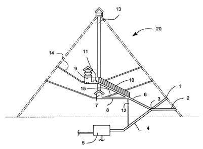
[0011] Fig. I Cutaway view of the invention.
DETAILED DESCRIPTION OF THE PREFERRED EMBODIMENT
[0012] A water condenser (20) in the shape of a large pyramidal structure is
built at a high altitude where the ambient temperature is generally
cooler. The water condenser (20) has a primary entry access (1), and an
air entry access (2) so as to bring air inside. Junction and gate (3)
between a condensate reservoir passageway (4) and a main
passageway (6) to control air flow. The condensate reservoir
passageway (4) leads to a condensate reservoir (5). And the main
passageway (6) provides access to condensation chambers (9, 10).
[0013] A boiler and heat diffuser (7) located in the center of the water
condenser (20) below the first and second condensation chambers
(9,10) heats up humid air which rises as steam into the first and second
condensation chambers (9,10) where it condenses on the cold surfaces
of the walls and ceiling (not shown). A chimney (13) evacuates
combustion by-products, if heat is produced by way of combustion and a
boiler air entry (15) provides air for combustion. There is a door (not
shown) in the boiler (7) to isolate from the rest of the water condenser
(20) so that water is not contaminated by the combustion gases.
i
CA 02692529 2010-02-08
[0014] The second condensation chamber (10) is connected to the first
condensation chamber (9) and collects water from it. Water level in
bottleneck (11) isolates the first condensation chamber (9) from the
second condensation chamber (10) by keeping some water level high
5 and thus blocking air inside to keep moisture level high and thus favor
more condensation. From the second condensation chamber (10), water
is directed downward by way of the main passageway (6), the
condensate reservoir passageway (4) and a channel (12), until it
reaches a cistern (5) located underground.
10[0015] The first and second condensation chambers (9, 10) are lined with
material such as ceramic or stainless steel which tend to remain cold
and favor condensation.
20
30
