Note: Descriptions are shown in the official language in which they were submitted.
CA 02692645 2011-10-07
68188-280
CLAMPING TOOL HOLDER
FIELD OF THE INVENTION
[00011 The present invention pertains to a clamping tool holder. More
particularly, the present invention relates to a clamping tool holder for
releasably
securing an insert to the toolholder.
BACKGROUND OF THE INVENTION
100021 Typically, tool holder mechanisms utilize a conical bore whose axis
is offset from the threaded section of the locking pin receiving hole to tilt
the
locking pin into abutment with the cutting insert. These designs are difficult
to
machine because the location of the conical bore must be maintained within a
relatively tight tolerance if it is to achieve the desired tilting of the
locking pin.
Therefore, there is a need to provide a tool holder for clamping an insert
that is
simple to manufacture and has improved manufacturing tolerances.
[00031 An example of a clamping toolholder is shown in U.S. patent No.
6,457,914.
SUMMARY OF THE INVENTION
[00041 In one aspect of the invention, a tool holder for releasably
clamping an insert within a tool holder body comprises a tool holder body
including an insert-receiving pocket formed at a forward end thereof and
having a
bottom and at least one side wall for receiving the insert. The bottom of the
insert-receiving pocket has a mounting bore. The tool holder body further
includes a clamp-securing bore having a central axis forming an angle with
respect
to a plane of the tool holder body. A clamp is arranged on the tool holder
body.
The clamp includes a nose portion with a downward extending nub having a
central axis forming an angle with respect to the plane of the tool holder
body.
The clamp includes a top surface, a forward lower face and a rearward lower
face,
and an aperture formed therethrough. A clamp screw is capable of being
inserted
through the aperture of the clamp and at least partially received in the clamp-
securing bore of the tool holder body to bring the clamp into pressing
engagement
with the insert, wherein only the nub of the nose portion of the clamp engages
a
rearward inside surface of the mounting bore of the insert, and wherein only
the
4-
CA 02692645 2010-01-05
WO 2009/011986 PCT/US2008/065876
forward lower face of the nose portion engages a top surface of the insert
when the
clamp is brought into pressing engagement with the insert.
[0005] In another aspect of the invention, a tool holder for releasably
securing an insert comprises a tool holder body including an insert-receiving
pocket formed at a forward end thereof. The tool holder body further includes
a
clamp-securing bore having a central axis forming an angle with respect to a
plane
of the tool holder body, and a pin-receiving bore having a central axis formed
at an
angle with respect to the plane of the tool holder body. A clamp is arranged
on the
tool holder body. The clamp includes a nose portion with a downward extending
nub having a central axis forming an angle with respect to the plane of the
tool
holder body. The clamp includes a top surface, a forward lower face and a
rearward lower face, and an aperture formed therethrough. A clamp screw is
capable of being inserted through the aperture of the clamp and at least
partially
received in the clamp-securing bore of the tool holder body to bring the clamp
into
pressing engagement with the insert. The clamp screw includes a head portion
having a lower face, wherein only the nub of the nose portion of the clamp
engages a rearward inside surface of the mounting bore of the insert, and
wherein
only the forward lower face of the nose portion engages a top surface of the
insert
when the clamp is brought into pressing engagement with the insert, and
wherein
only a forward end of the lower face of the head portion of the clamp screw
engages the top surface of the clamp when the clamp is brought into pressing
engagement with the insert.
[0006] In another aspect of the invention, a method of clamping an insert
to a tool body, comprises the steps of:
providing a tool holder body including an insert-receiving pocket
formed at a forward end thereof and having a bottom and at least one side wall
for
receiving the insert, the bottom of the insert-receiving pocket having a
mounting
bore, the tool holder body further including a clamp-securing bore having a
central
axis forming an angle with respect to a plane of the tool holder body;
providing a clamp arranged on the tool holder body, the clamp
including a nose portion with a downward extending nub having a central axis
forming an angle with respect to the plane of the tool holder body, the clamp
-2-
CA 02692645 2011-10-07
68188-280
including a top surface, a forward lower face and a rearward lower face, and
an
aperture formed therethrough; and
inserting a clamp screw into the aperture of the clamp and at least
partially received in the clamp-securing bore of the tool holder body to bring
the
clamp into pressing engagement with the insert,
whereby only the nub of the nose portion of the clamp engages a
rearward inside surface of the mounting bore of the insert, and
whereby only the forward lower face of the nose portion engages a top
surface of the insert when the clamp is brought into pressing engagement with
the
insert.
In accordance with another aspect of the invention, there is provided a
tool holder for releasably securing an insert, comprising: a tool holder body
including
an insert-receiving pocket formed at a forward end thereof and having a bottom
and
at least one side wall for receiving the insert, the tool holder body further
including a
clamp-securing bore having a central axis forming an angle with respect to a
plane of
the tool holder body; a clamp arranged on the tool holder body, the clamp
including a
top surface, a forward lower face and a rearward lower face, and an aperture
formed
therethrough, the clamp including a nose portion with a downward extending
nub;
and a clamp screw capable of being inserted through the aperture of the clamp
and
at least partially received in the clamp-securing bore of the tool holder body
to bring
the clamp into pressing engagement with the insert, the clamp screw including
a
head portion, a shoulder and a threaded portion; and a ring disposed about the
shoulder of the clamp screw, wherein only the nub of the nose portion of the
clamp
engages a rearward inside surface of a mounting bore of the insert when the
clamp is
brought into pressing engagement with the insert, and wherein only the forward
lower
face of the nose portion engages a top surface of the insert when the clamp is
brought into pressing engagement with the insert.
3
CA 02692645 2011-10-07
68188-280
In accordance with another aspect of the invention, there is provided a
tool holder for releasably securing an insert, comprising: a tool holder body
including
an insert-receiving pocket formed at a forward end thereof, the tool holder
body
further including a clamp-securing bore having a central axis forming an angle
with
respect to a plane of the tool holder body, and a pin-receiving bore having a
central
axis formed at an angle with respect to the plane of the tool holder body; a
clamp
arranged on the tool holder body, the clamp including a top surface, a forward
lower
face and a rearward lower face, and an aperture formed therethrough, the clamp
including a nose portion with a downward extending nub; a clamp screw capable
of
being inserted through the aperture of the clamp and at least partially
received in the
clamp-securing bore of the tool holder body to bring the clamp into pressing
engagement with the insert, the clamp screw including a head portion having a
lower
face, a shoulder and a threaded portion; and a ring disposed about the
shoulder of
the clamp screw, wherein only the nub of the nose portion of the clamp engages
a
rearward inside surface of a mounting bore of the insert, and wherein only the
forward lower face of the nose portion engages a top surface of the insert
when the
clamp is brought into pressing engagement with the insert, and wherein only a
forward end of the lower face of the head portion of the clamp screw engages
the top
surface of the clamp when the clamp is brought into pressing engagement with
the
insert.
In accordance with another aspect of the invention, there is provided a
method of clamping an insert to a tool body, comprising the steps of:
providing a tool
holder body including an insert-receiving pocket formed at a forward end
thereof and
having a bottom and at least one side wall for receiving the insert, the tool
holder
body further including a clamp-securing bore having a central axis forming an
angle
with respect to a plane of the tool holder body; providing a clamp arranged on
the tool
holder body, the clamp including a top surface, a forward lower face and a
rearward
lower face, and an aperture formed therethrough, the clamp including a nose
portion
with a downward extending nub; inserting a clamp screw into the aperture of
the
clamp and at least partially received in the clamp-securing bore of the tool
holder
3a
CA 02692645 2011-10-07
68188-280
body to bring the clamp into pressing engagement with the insert, the clamp
screw
including a head portion, a shoulder and a threaded portion; and disposing a
ring
about the shoulder of the clamp screw, whereby only the nub of the nose
portion of
the clamp engages a rearward inside surface of a mounting bore of the insert,
and
whereby only the forward lower face of the nose portion engages a top surface
of the
insert when the clamp is brought into pressing engagement with the insert.
BRIEF DESCRIPTION OF THE DRAWINGS
100071 While various embodiments of the invention are illustrated, the
particular embodiments shown should not be construed to limit the claims. It
is
anticipated that various changes and modifications may be made without
departing
from the scope of this invention.
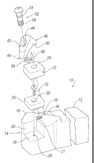
100081 Fig. I is an exploded side perspective view of a clamping tool
holder in accordance with an embodiment of the invention.
[00091 Fig. 2 is a top view of the clamping tool holder in an unclamped
position in accordance with an embodiment of the invention.
1000101 Fig. 3 is a partial cutaway cross-sectional view of the clamping tool
holder in an unclamped position taken along line 3-3 of Fig. 2.
[000111 Fig. 4 is an enlarged cross-sectional view of the nub of the nose
portion of the clamp in accordance with an embodiment of the invention.
[000121 Fig. 5 is an exploded perspective view of the clamp screw and ring
in accordance with an embodiment of the invention.
1000131 Fig. 6 is a top view of the clamping tool holder in the clamped
position in accordance with an embodiment of the invention.
1000141 Fig. 7 is a partial cutaway cross-sectional view of the clamping tool
holder in the clamped position taken along line 7-7 of Fig. 6.
[000151 Fig. 8 is an enlarged view of the inclined surfaces at different
angles that act as a ramp and create a pivot point when the clamping tool
holder is
in the clamped position.
3b
CA 02692645 2010-01-05
WO 2009/011986 PCT/US2008/065876
[00016] Fig. 9 is an enlarged partial side view of the clamping tool holder in
the clamped position in accordance with the invention.
[00017] Fig. 10 is a side view of a clamp, a clamp screw, a ring and a
tapered spring for biasing the clamp in accordance with an alternate
embodiment
of the invention.
[00018] Fig. 11 is a side view of a clamp, a clamp screw and a tapered
spring for biasing the clamp in accordance with an alternate embodiment of the
invention.
[00019] Fig. 12 is a side view of a clamping tool holder in which the central
axis of the clamp-securing bore is substantially perpendicular to a plane of
the tool
holder body in accordance with an alternate embodiment of the invention.
DETAILED DESCRIPTION OF THE INVENTION
[00020] Referring now to Figs. 1-9, a clamping tool holder 10 is shown
according to an embodiment of the invention. The clamping tool holder 10
comprises a tool holder body 12 having an insert-receiving pocket 14 formed in
its
upper surface 16 at a corner of its forward end portion. The insert receiving
pocket 14 has a bottom 18 and angularly-disposed side walls 20 forming an apex
21 at the intersection between the side walls 20. An insert 22 having a
mounting
bore 24 formed therethrough is disposed on the bottom 18 of the pocket 14 with
a
seat member 26 therebetween. Although the insert 22 can be any shape, the
illustrated insert 22 is generally diamond in shape having a top surface 22a
(Fig. 2). An internally threaded bore 28 is formed in the bottom 18 of the
pocket
14, and a bore 30 having an upper portion tapering downward is formed through
the seat member 26. The seat member 26 is fixedly secured to the insert-
receiving
pocket 14 by means of a countersunk screw 32 inserted through the bore 30 and
screwed into the threaded bore 28. In an alternative embodiment, the insert 22
can
be disposed on the bottom 18 of the pocket 14 without the use of the seat
member
26 and the head screw 32. In this alternative embodiment, it is not necessary
to
include the threaded bore 28 in the tool holder body 12.
[00021] As seen in Fig. 3, an inclined surface 34 sloping inwardly in a
direction away from the insert-receiving pocket 14 is formed on that portion
of the
upper surface 16 of the tool body 12 that is displaced rearwardly of the tool
body
-4-
CA 02692645 2010-01-05
WO 2009/011986 PCT/US2008/065876
12 with respect to the pocket 14. An internally threaded clamp-securing bore
36 is
formed in the tool holder 10 and is located between the inclined surface 34
and the
insert-receiving pocket 14. The inclined surface 34 is formed at a prescribed
angle
35 with respect to a central axis 66 of the clamp-securing bore 36. In an
embodiment, the angle 35 is about 24 degrees. In this embodiment, the central
axis 66 of the clamp-securing bore 36 forms an angle 68 that is not
perpendicular
to a plane 70 formed by the upper surface 16 of the body 12, as shown in Fig.
3.
[00022] The tool holder 10 further includes a pin-receiving bore 38 formed
in the body 12 of the tool holder 10. The pin-receiving bore 38 maintains
alignment of the clamp 40 and the tool body 12 as the clamp 40 presses
downward
and rearward on the insert 22. In the illustrated embodiment, the inclined
surface
34 is located between a pin-receiving bore 38 and the clamp-securing bore 36.
Alternatively, the pin-receiving bore 38 can be located between the inclined
surface 34 and the clamp-securing bore 36. In this embodiment, a central axis
72
of the pin-receiving bore 3 8 is substantially parallel with the central axis
66 of the
clamp-securing bore 36. Thus, the central axis 72 of the pin-receiving bore 38
forms an angle 68 that is not perpendicular to a plane 70 of the body 12, as
shown
in Fig. 3.
[00023] A clamp 40 is arranged on the upper surface 16 of the tool holder
body 12. As shown in Figs. 1, 6 and 7, the clamp 40 is of a generally C-shape
in
side elevation having a tapered forward portion 42 and tapered side portions
42a,
42b to provide a low profile design. The low profile design facilitates the
removal
of chips during the cutting process. Formed in the center of the clamp 40 is a
non-
circular or oblong-shaped aperture 44 having a greater dimension along its
longitudinal axis. The non-circular aperture 44 allows for some movement of
the
clamp 40 along its longitudinal axis, but does not allow as much movement
perpendicular to the longitudinal axis of the clamp 40. As shown in Fig. 1,
the
aperture 44 is formed so that its central axis is substantially concentric
with the
central axis 66 of the clamp-securing bore 36 of the tool body 12. The clamp
40
also includes a top surface portion 40a, a substantially planar forward lower
face
40b and a substantially planar rearward lower face 40c, as shown in Fig. 3.
[00024] As seen in Fig. 3, the forward end of the clamp 40 includes an
arcuately-shaped nose portion 46 having a lower face 46a to be held in
-5-
CA 02692645 2010-01-05
WO 2009/011986 PCT/US2008/065876
engagement with the top surface 22a of the insert 22. The forward lower face
46a
of the nose portion 46 assist in distributing the downward and rearward force
of
the clamp 40 over the top surface 22a of the insert 22. The forward lower face
40b
of the clamp 40 is formed so as to be positioned higher in elevation than the
forward lower face 46a of the nose portion 46 so as to not engage the insert
22
when the forward lower face 46a of the nose portion 46 engages the top surface
22a of the insert 22, as shown in Figs. 6 and 7.
[00025] The clamp 40 has an inclined surface 50 formed at a proximal end
thereof so as to protrude downward and rearward with respect to the clamp-
receiving bore 36. The inclined surfaces 34, 50 act as ramp surfaces when the
tool
holder 10 is moved from an unclamped position to a clamped position, and vice
versa. However, the inclined surface 50 is formed at an angle 37 with respect
to
the central axis 66 of the clamp-receiving bore 36 that is slightly different
than the
angle 35 of the inclined surface 34 of the tool holder 10. In an embodiment,
the
angle 37 is about 24 degrees. As seen in Fig. 3, this difference between the
angles
35, 37 causes the clamp 40 to pivot about a pivot point 39 (Figs. 8 and 9)
when the
tool holder 10 is moved from the unclamped position to the clamped position.
In
the illustrated embodiment, the pivot point 39 is located at the intersection
between the upper surface 16 and the inclined surface 34 of the tool holder
10.
This pivoting action of the clamp 40 causes the clamp 40 to further exert a
force
downward and rearward when bringing the clamp 40 into pressing engagement
with the insert 22, thereby enhancing the "pull back" feature of the
invention.
[00026] It should be noted that the relative angle between the clamp-
securing bore 36 and the inclined surfaces 34, 50 can be "tuned" to provide a
desired downward force and/or rearward force on the insert 22. In one
embodiment, the angle of the clamp-securing bore 36 of the inclined surfaces
34,
50 are approximately 24 degrees with respect to the central axis 66 of the
clamp-
receiving bore 36 to provide slightly more downward force than rearward force
on
the insert 22. However, it will be appreciated that the relative angle between
the
clamp-securing bore 36 and the inclined surfaces 34, 50 may be any desired
angle
to provide the desired ratio of downward to rearward force on the insert 22.
[00027] Referring now to Figs. 3 and 4, the clamp 40 includes a downward
extending nub 48 that engages the mounting bore 24 of the insert 22 when the
tool
-6-
CA 02692645 2010-01-05
WO 2009/011986 PCT/US2008/065876
holder 10 is brought into the clamped position. In this embodiment, a central
axis
76 of the nub 48 is substantially perpendicular to the forward lower face 40b
of the
clamp 40, as shown in Figs. 3 and 7. The central axes 66, 72 of the clamp-
securing bore 36 and the pin-receiving bore 38 are at angle 62, 64 with
respect to
the central axis 76 of the nub 48. In an embodiment, the angles 62, 64 are
approximately 20 degrees that causes the nub 48 to engage the rearward inner
surface of the mounting bore 24 along a flat surface that defines a line or
surface
area of contact 48a of the nub 48 and exert a force downward and rearward on
the
insert 22. This downward and rearward force may or may not be in alignment
with the apex 21 of the pocket 14. In one embodiment, the flat surface that
defines the line or surface area of contact 48a may be about 0.0 10 inches
(0.254 mm).
[00028] The clamp 40 also includes a pin-receiving slot 63 positioned
between the inclined surface 50 and a rear surface 40d of the clamp 40. As
shown
in Figs. 3 and 7, the pin-receiving slot 63 of the clamp 40 is formed so that
its axis
is substantially concentric with the axis of the pin-receiving bore 38 of the
body 12
of the tool holder 10. The pin-receiving slot 63 may be non-circular or oblong-
shaped having a greater dimension along its longitudinal axis. The non-
circular
pin-receiving slot 63 allows for some movement along its longitudinal axis,
but
does not allow as much movement perpendicular to the longitudinal axis. A
guide
pin 60 is disposed within the pin-receiving bore 38 and the pin-receiving slot
63 to
prevent the clamp 40 from spinning or twisting in a radial direction (in a
direction
perpendicular to the direction of travel of the clamp screw 52) when turning
of the
clamp screw 52 to loosen or tighten the clamp 40. Although the guide pin 60
can
be formed of a solid pin, the guide pin 60 is preferably formed of a slotted
spring
pin that can flex, expand or compress to allow for variations in design and
wear of
the tool holder 10. Specifically, the slotted spring pin 60 can flex to
maintain the
relative positions of the aperture 44, the bore 36, the pin-receiving bore 38
of the
tool body 12 and the pin-receiving slot 63 of the clamp 40 to compensate for
changes in the relative angle of the central axes 76, 66, 72 of the bores 24,
36, 38,
respectively, that may result due to manufacturing tolerances and wear of the
tool
body 12 and the clamp 40 (i.e., alignment creep). The guide pin 60 can be
press
fit into the pin-receiving bore 38 of the tool holder body 12. The length of
the
-7-
CA 02692645 2010-01-05
WO 2009/011986 PCT/US2008/065876
guide pin 60 is selected to allow the clamp 40 to move away from the insert 22
while preventing the clamp 40 from spinning or twisting in the radial
direction.
[00029] It will be appreciated that the smaller width of the pin-receiving
slot 63 can be slightly larger than the diameter of the guide pin 60 to allow
free
movement of the guide pin 60 within the pin-receiving slot 63. It will be
appreciated that the pin-receiving slot 63 and guide pin 60 can be eliminated
by
forming the inclined surfaces 34, 50 with convex, concave or contour
complementary shaped surfaces. Oppositely, the inclined surfaces 34, 50 can be
eliminated and made integral with the guide pin 60 or attached as a separate
component when retrofitting a conventional tool holder.
[00030] Referring now to Fig. 3 and 5, the clamp 40 is secured to the tool
holder body 12 by means of a clamp screw 52 having a head portion 53, a
shoulder
54 and a threaded portion 56. The head portion 53 includes a lower face 53a
that
is substantially perpendicular to the central axis 66 of the clamp-receiving
bore 36,
as shown in Fig. 9. However, the top surface 40a of the clamp 40 forms an
angle
with respect to the lower face 53a when the tool holder 10 is placed in the
clamped
position. As a result, only the front portion of the lower face 53a engages
the top
surface 40a of the clamp 40 when the tool holder 10 is brought into the
clamped
position, as shown in Fig. 9.
[00031] During assembly of the tool holder 10, the threaded portion 56 is
inserted through the aperture 44 and screwed into the threaded clamp-securing
bore 36. It will be appreciated that the threads of the bore 36 may be
slightly
larger than the threads of the clamp screw 52 to allow for variations in
design, i.e.
manufacturing tolerances in the tool holder 10.
[00032] In one embodiment, a ring 58 is press-fit to the shoulder 54 to assist
in lifting the clamp 40 when the tool holder 10 is moved from the clamped
position to the unclamped position, as seen in Figs. 3 and 5. In another
embodiment shown in Fig. 10, the ring 58 is used in combination with a tapered
spring 61 that provides a biasing force to cause the clamp 40 to lift from the
body
12 when the clamp screw 52 is rotated in a counter clockwise direction.
[00033] However, the ring 58 is not necessary for lifting the clamp 40 from
the tool holder 10. In another embodiment shown in Fig. 11, the ring 58 is
-8-
CA 02692645 2010-01-05
WO 2009/011986 PCT/US2008/065876
omitted and only the tapered spring 61 is used to assist in lifting the clamp
40. In
this embodiment, the bottom of the tapered spring 61 abuts the shoulder 54 of
the
clamp screw 52. It will be appreciated that the invention is not limited by
the use
of a tapered spring, and that the invention can be practiced using any means
for
providing a biasing force to assist in lifting the clamp when the tool holder
10 is
moved from the clamped position to the unclamped position.
[00034] With reference to Figs. 6-9, the clamping operation of the tool
holder 10 using the clamp 40 will now be described. Usually, since the
clamping
operation is required only when replacing the cutting insert with a new one,
it is
normally not necessary to move the clamp 40 upward from the clamped position
shown in Fig. 7 to the unclamped position shown in Fig. 3. Therefore, there
may
be provided a stop member (not shown) to prevent the clamp screw 52 from being
further loosened from the state shown in Fig. 3.
[00035] From the unclamped position shown in Fig. 3, the clamp screw 52
is rotated in a clockwise direction to screw the clamp screw 52 into the clamp-
securing bore 36 and cause the clamp 40 to move downward and rearward with
respect to the insert 22. The clamp 40 is guided by guide pin 60 as it moves
downward and rearward along the axis of the pin-receiving bore 38 of the body
12
of the tool holder 10. It should be noted that the nub 48 of the clamp 40
moves in
a direction that may or may not be in alignment with the apex 21 of the pocket
14.
[00036] As the clamp 40 is further tightened by turning the clamp screw 52,
the line of contact 48a of the nub 48 positively engages the rear inner
surface of
the mounting bore 24 of the insert 22. In addition, only the forward lower
face
46a of the nose portion 46 engages the top surface 22a of the insert 22 when
in the
clamped position. As the clamp 40 is further tightened, the lower face 53a of
the
clamp screw 52 engages the top surface 40a of the clamp 40, further causing
the
forward lower face 46a of the clamp 40 to press against the top surface 22a of
the
insert 22. Further, the inclined surfaces 34, 50 act as a ramp about the pivot
point
39 to further cause the clamp 40 to press the insert 22 downward and rearward
to
further secure the insert 22 to the pocket 14.
[00037] As shown in Fig. 4, one aspect of the invention is that only the line
of contact 48a of the nub 48 contacts the inner surface of the mounting bore
24
-9-
CA 02692645 2010-01-05
WO 2009/011986 PCT/US2008/065876
when the clamp 40 is brought into pressing engagement with the insert 22. As
shown in Fig. 9, another aspect of the invention is that only the forward
lower face
46a of the nose portion 46 of the clamp 40 contacts the top surface 22a of the
insert 22 when the clamp 40 is brought into pressing engagement with the
insert
22. In other words, the forward lower face 46a forms an angle 80 with respect
to
the top surface 22a of the insert 22 when the clamp 40 is brought into
pressing
engagement with the insert 22. Another aspect of the invention is that the
forward
lower face 40b of the clamp 40 does not engage the insert 22 when the clamp 40
is
brought into pressing engagement with the insert 22 because the forward lower
face 40b is formed at a higher elevation than the forward lower face 46a of
the
nose portion 46. Yet another aspect of the invention is that only the forward
lower
face 53a of the clamp screw 52 engages the top surface 40a of the clamp 40 to
further bring the nub 48 and the forward lower end 46a into pressing
engagement
with the insert 22. In other words, the forward lower face 53a forms an angle
82
with respect to the top surface 40a of the clamp 40 when the clamp 40 is
brought
into pressing engagement with the insert 22. Still yet another aspect of the
invention is that the inclined surfaces 34, 50 are formed at different angles
with
respect to the central axis 66 of the bore 36, thereby causing the clamp 40 to
pivot
about the pivot point 39 to further bring the nub 48 and the forward lower
face 46a
into pressing engagement with the insert 22.
[00038] It will be appreciated that the invention is not limited by the type
and shape of the insert 22, and that the invention can be practiced with any
desirable shape and type of insert. For example, when the insert 22 is
triangular in
shape, rather than square or rectangular, the receiving pocket 14 can also be
triangular in shape to accommodate the shape of the insert 22.
[00039] When removing the insert 22 from the tool holder body 12, the
clamp screw 52 is turned in a counter clockwise direction to cause the ring 58
to
engage a ledge 44a of the clamp 40 to assist in lifting the clamp 40, as shown
in
Fig. 3. As the clamp screw 52 is further turned, the inclined surface 50 is
separated from the inclined surface 34, as shown in Fig. 3. In this released
condition, the nose portion 46 of the clamp 40 is positioned above the insert
22
such that the insert 22 can be easily removed and replaced by a new insert 22.
-10-
CA 02692645 2011-10-07
68188-280
Accordingly, the clamp 40 is released such that replacing operation for the
insert
22 can be conducted efficiently.
(00040) Refen-ing now to Fig. 12, a clamping tool holder 100 is shown
according to another embodiment of the invention. In this embodiment, the
central axis 66 of the clamp-securing bore 36 is substantially perpendicular
to the
plane 70 of the body 12, unlike the tool holder 10 in which the central axis
66 is
not substantially perpendicular to the plane 70. Thus, the angle 68 is
approximately 90 degrees in the tool holder 100, unlike the tool holder 10 in
which the angle 68 is greater than 90 degrees. A resilient member such as a
spring
may be used for providing a biasing force to assist in lifting the clamp when
the
tool holder 10 is moved from the clamped position to the unclamped position..
[00041) In the illustrated embodiment, the central axis 72 of the pin-
receiving bore 38 in the tool holder 100 is substantially parallel to the
central axis
66 of the clamp-securing bore 36. In other words, the angle 74 is
approximately
equal to 90 degrees. As a result, the central axes 66, 72 of the clamp-
securing
bore 36 and the pin-receiving bore 38 do not intersect one another. However,
in
another embodiment, the angle 74 could be other than 90 degrees and the
central
axes 66, 72 could intersect one another.
[000421
[00043) Having described presently preferred embodiments the invention
may be otherwise embodied within the scope of the appended claims.
-11-