Note: Descriptions are shown in the official language in which they were submitted.
CA 02692972 2010-02-11
METHOD FOR CONTROLLING A HYDROCARBONS PRODUCTION
INSTALLATION
The present invention relates to a method for controlling a hydrocarbons
production installation. The method is applied to an installation comprising
one or more
hydrocarbons production strings.
Document FR 2 783 557 relates to a method for controlling a liquid and gaseous
hydrocarbons production well activated by gas injection. The well comprises at
least one
production string equipped with an outlet choke with an adjustable or variable
aperture.
Pressurized gas. the flow rate of which is adjustable using a control valve,
is injected
into the annular string. The method comprises a start-up phase that consists
of carrying
out the following series of steps:
- a step of initiating the hydrocarbons production,
- a step of ramping up to production speed,
followed by a production phase. During these phases, the outlet choke of the
production string concerned (if the installation comprises several strings,
the various
chokes are operated) and the control valve are operated in order to maintain
the stability
of the flow rate of the hydrocarbons produced.
Said document describes a sequential control operation of the well valves. The
drawback of such a sequential operation is the difficulty of adapting to the
instabilities
of the well, resulting in an undesirable variation in the liquid flow rate or
gaseous flow
rate at the wellhead. Such instabilities prolong the start-up time of the
well. Furthermore,
a drawback of the operation described in said document is that certain phases
of the
operation are governed by too long a time lag, which delays the production
phase.
Document EP 0 756 065 describes a system for controlling the hydrocarbons
production using a production string that extends into a production well. Gas
is injected
at the bottom of the string. The system comprises a choke with a. variable or
adjustable
aperture for adjusting the flow of hydrocarbons in the production string and
comprises a
control module for dynamically controlling the choke aperture. The system
described is
a dynamic choke aperture adjustment system, but the drawback of such a system
is that
the start-up of the well is not carried out under optimum conditions. In
particular, the
CA 02692972 2010-02-11
2
system described does not allow appropriate management of the occurrence of
hydrocarbons plugs at the well start-up. In effect, a system operating solely
continuously
does not allow free action on the gas production and injection chokes to allow
plugs to
be expelled. Similarly, if such a continuous system drifts, it is not possible
to make good
by a stabilizing mode of operation.
Document US 6 595 294 describes a method for controlling the production flow
rate of a well. The well comprises a production string with at least one
production choke
and gas injection means comprising at least one gas injection choke. At least
one of the
chokes is controlled continuously using a model-based control system. The
system
comprises a stabilization controller based on a dynamic return of at least one
of the
elements chosen from a measurement of pressure, temperatures or flow rates in
the well.
These pressures, temperatures and flow rates are effectively stabilized by the
model-
based control system at specified operation points, even if the specified
operation point
is unstable in an open loop. The operation described is a dynamic adjustment
operation
but is based on the use of a mathematical model.
However, an operation based on the use of a model has drawbacks. One drawback
is that it is difficult for a model to take account of the temperature of the
valves at the
moment of start-up. This temperature has an effect on the manner of start-up
of the well.
Also, a further drawback is that it is difficult for a model to take account
of the state of
the fluids around the well, which are unpredictable. These drawbacks thus do
not allow
start-up of the well under conditions as close as possible to the actual well
conditions.
The document Automatic Control of Unstable Gas Liflcd Wells (SPE 56832, by
Bard, Lemetayer et al, 1999) describes methods centred on manipulation of the
production and gas injection valves. In this article, the methods are
described as
alternatives and are the methods forming the subjects of patents US 6 595 294
and FR
2 783 557.
Other methods are disclosed in documents WO 2006/067151, WO 00/75477, US
5 413 175, US 2006/041392, "Cascade control of unstable systems with
application to
stabilization of slug flow" by Espen Storkaas and Sigurd Skogestad (IFAC-
SYMPOSIUM ADCHEM), and "Stabilization of gas lifted wells based on state
estimation" by Gisle Otto Eikrem et at. (IFAC), the contents of each of which
are hereby
CA 02692972 2010-02-11
3
incorporated by reference. While these prior art methods have achieved a
varying degree
of success, the art is constantly in need of a method for controlling a
hydrocarbons
production installation that solves all or some of the above problems.
To this end, the invention proposes a method for controlling a hydrocarbons
production installation, the latter comprising:
- at least one hydrocarbons production string activated by a gas injection
using a
gas injection choke, and
- a production choke on the string,
the method comprising a production phase during which the position of at least
one of the chokes is adjusted by cascaded control loops, the loops being
driven
according to continuously or sequentially developing setpoint parameters.
According to a variant, during the production phase, the position of the
production
choke is adjusted by cascaded control loops, the loops being driven according
to
continuously or sequentially developing setpoint parameters.
According to a variant, the position of the production choke is continuously
adjusted by the control loops.
According to a variant, during the production phase, the position of the gas
injection choke is continuously adjusted by cascaded control loops, the loops
being
driven according to continuously or sequentially developing setpoint
parameters.
According to a variant, the method comprises, prior to the production phase, a
start-up phase during which:
- the position of the production choke is sequentially adjusted and
- the position of the gas injection choke is continuously adjusted by a
control loop
driven according to continuously or sequentially developing sctpoint
parameters.
According to a variant, the loops are also driven according to parameters
measured
on the installation or calculated.
According to a variant, the parameters are chosen from a group comprising in
particular the pressure at the head of the production string, the pressure in
the production
string, the pressure at the top of the injection string, the flow rate of the
gas injected by
the gas injection choke, the gas flow rate at the gas injection point into the
production
string.
CA 02692972 2010-02-11
4
According to a variant, the position of the production string is adjusted by
the
control loops also according to a final setpoint aperture of the production
string or
according to a setpoint aperture of the production choke that increases
sequentially.
According to a variant, the method comprises a loop for the continuous
adjustment
of the setpoint pressure in the production string according to the measured
aperture of
the production choke and a reference aperture of the production choke.
According to a variant, the method comprises a loop for the continuous
adjustment
of the setpoint pressure at the string head according to the setpoint pressure
in the
production string and a pressure in the production string obtained by
calculation or by
measurement.
According to a variant, the method comprises a loop for the continuous
adjustment
of the production choke aperture according to the setpoint pressure at the
string head and
according to the measured pressure at the string head.
According to a variant, the method comprises a loop for the adjustment of a
reference gas flow rate according to the setpoint pressure at the gas
injection point into
the production string and a pressure in the string obtained by calculation or
by
measurement.
According to a variant, the method comprises a loop for the continuous
adjustment
of the gas injection choke aperture according to the reference gas flow rate
and
according to the setpoint gas flow rate.
According to a variant, the position of the gas injection choke is adjusted by
the
control loops also according to a setpoint gas flow rate at the point of gas
injection into
the production string, the setpoint gas flow rate at the gas injection point
in the
production string increasing sequentially.
According to a variant, the method comprises a loop for the continuous
adjustment
of the gas injection choke aperture according to a setpoint gas flow rate and
according to
the gas flow rate measured or calculated at the point of gas injection into
the production
string.
According to a variant, the method also comprises a loop for the adjustment of
the
maximum setpoint aperture of the production choke according to a pressure
measured
CA 02692972 2010-02-11
downstream of the production choke and a reference pressure downstream of the
production choke.
According to a variant, the hydrocarbons production choke is open according to
the smallest aperture between the maximum setpoint aperture and the previously
5 obtained aperture.
According to a variant, the installation comprises a plurality of strings.
Further characteristics and advantages of the invention will become apparent
on
reading the following detailed description of the embodiments of the
invention, given by
way of example only and with reference to the drawings, which show:
- Figure 1, a diagrammatic representation of a production installation;
- Figures 2 to 4, production control loops.
The invention relates to a method for controlling a hydrocarbons production
installation. The installation comprises at least one hydrocarbons production
string
activated by a gas injection using a gas injection choke, and a production
choke on the
string. The method comprises notably a production phase during which the
position of at
least one of the chokes is adjusted by cascaded control loops. The loops are
driven
according to continuously or sequentially developing setpoint parameters. The
invention
makes it possible to control the installation more accurately and quickly than
in the prior
art, as a cascade control loop architecture makes it possible to simplify each
of the loops
in order to increase the speed of implementation, while still taking account
of a greater
number of setpoint parameters.
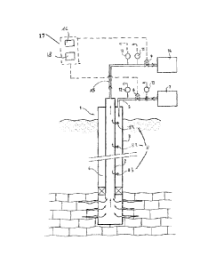
Figure I shows a hydrocarbons production installation. According to Figure 1,
the
installation allows production on a hydrocarbons well (oil and gas).
Application to a
well will be described. non-l imitatively, below. In effect, the application
to a well is
given by way of example as the description of the production control can be
applied to a
string linking a wellhead on the sea bed and a platform above sea-level.
The well is activated by gas injection from a pressurized gas source. The well
I
supplies hydrocarbons treatment units downstream. The well comprises at least
one
production string 2 (or "tubing"). The installation can comprise more than one
string. A
lining 3 surrounds the string 2. At the foot of the lining 3, apertures allow
hydrocarbons
to pass from the earth to the string 2. A space 4 (or "casing") is defined
between the
CA 02692972 2010-02-11
6
string 2 and the lining 3. This space 4 is annular around the string 2. The
space 4 is
plugged using a "packer". This makes it possible to isolate the space 4 from
the bottom
of the lining 3. Thus, the hydrocarbons are channelled towards the inside of
the string 2.
It can also be envisaged that the space 4 is not plugged, or that the gases
are conveyed
by a dedicated closed tube.
Figure 1 also shows an exit pipe 15 of the hydrocarbons produced. The exit
pipe
links the upper part of the string 2 to downstream treatment units 14. A
hydrocarbons
production choke 9 can be provided on the exit pipe 15 to control the
hydrocarbons flow
rate. This choke is a calibrated orifice allowing the flow rate of the well to
be adjusted.
10 The choke 9 has an adjustable aperture. A sensor 10 for measuring the
temperature
upstream of the choke 9 delivers an electronic signal representing the
temperature
upstream of the choke 9. Also, a pressure sensor I I upstream of the choke 9
delivers an
electronic signal representing the pressure upstream of the choke 9.
A pressurized gas source 7 allows the space 4 to be supplied. The string 2
15 comprises a plurality of valves 8 (81, 82, 83 by way of example) for gas to
enter the
string 2 from the space 4. These valves correspond to gas injection points
into the
string. These points can be at different heights or levels with respect to the
string head.
A flow line 5 allows the injection of gas into the space 4 from the gas source
7. A choke
6 allows the flow rate of injected gas to be controlled. A pressure sensor 12
downstream
of the choke 6 delivers an electronic signal representing the pressure
downstream of this
choke 6. Also, a sensor 13 of the injected gas flow rate, located upstream of
the choke
6. delivers an electronic signal representing the flow rate of injected gas.
A logic controller 17 comprises a programmable module 16. The logic controller
17. and in particular the module 16, delivers signals controlling the
production choke 9
and the gas injection choke 6. The module 16 can comprise a memory previously
loaded
with a control program and useful data for controlling production, in
particular all the
predetermined values for the adjustment variables. The module 16 also provides
the
closed-loop control of the injected gas flow rate by acting on the valve 6
according to
the signals delivered by sensors 10, 11, 12 and 13.
The logic controller 17 also comprises a production control module 18. The
module 18 allows the cascaded corrections, described below, to be carried out
on the
CA 02692972 2010-02-11
7
production 9 and injection 6 chokes based on values that are measured or
calculated at
the surface and at the bottom.
Figure 2 shows a possible arrangement of loops of the module 18 making it
possible in particular to operate the production choke 9.
The loop 100 of the module 18 (called the "high level" loop) makes it possible
to
continuously adjust a setpoint pressure 103 in the production string according
to the
measured aperture 101 of the production choke and a reference aperture 102 of
the
production choke. The setpoint pressure 103 is continuously adjusted in so far
as the
value of this setpoint pressure 103 is constantly modified. This loop 100
makes it
possible to adapt the value of the setpoint pressure in the production string
according to
the current state of the position of the production choke and the previously-
assigned
reference aperture. A progressive transition is obtained towards an optimized
value of
this setpoint pressure in the production string. Adjustment of the setpoint
pressure 103 in
the string makes it possible to anticipate instabilities likely to arise at
the bottom of the
5 string in order to limit their increase.
The loop 200 of the module 18 (called the "main" loop) allows continuous
adjustment of the setpoint pressure 201 at the string head according to the
setpoint
pressure 103 in the production string 2 and according to a pressure 80
calculated or
measured in the string 2. The setpoint pressure 103 is calculated by the loop
100. The
setpoint pressure 201 at the string head is continuously adjusted in so far as
this setpoint
pressure 201 is constantly modified. The loop 200 is implemented in a cascade
with
respect to the loop 100 in so far as the result of the loop 100 is taken into
account by the
loop 200. The pressure 80 is described in greater detail below.
The loop 300 of the module 18 (called the "low level" loop) allows continuous
adjustment of the aperture 301 of the hydrocarbons production choke according
to the
setpoint pressure 201 at the head of the production string and according to
the pressure
202 measured at the head of the production string. The setpoint pressure 201
at the head
of the production string is provided by the loop 200. The pressure 202
measured at the
string head is supplied by the sensor 11. At the end of the loop 300, all
aperture 301 of
the choke 9 is obtained that is adapted so that the actual pressure at the
string head
approaches the setpoint pressure 201.
CA 02692972 2010-02-11
8
As the aperture of the production choke has an influence on the control of the
well,
the continuous adjustment, such as is carried out for example by the loop 300
makes it
possible to control the well better and to anticipate its reactions. Thus it
is possible to
control the aperture of the choke as a function both of production targets and
of the
behaviour of the well at the wellhead and along the production string.
The loop 400 of the module 18 makes it possible to take account respectively
the
aperture 301 of the choke 9 calculated in step 300 or the aperture 401
proposed by the
module 16 in order to choose an aperture 402. Preferably, the aperture 401
will be used
if the latter is less than the aperture 301 for better safety of the
installation.
The loop 500 of the module 18 (called the "anti-PSH loop") makes it possible
to
limit the aperture 401 of the production choke 9 calculated by the module 16
or the
aperture 301 determined by the loop 300. Restriction of the aperture of the
choke 9 is
carried out according to the pressure in the hydrocarbon dispatch line
downstream of the
production choke 9. This loop is particularly useful for limiting the risks of
overpressure.
The loop 500 comprises a step 501 which determines an aperture 502 of the
choke
9 according to a pressure 503 measured in the despatch line and a reference
pressure 504
in this same line. In the step 505, the aperture 502 is compared with the
aperture 402
determined in step 400.
The loop 500 is well suited to the various ways of controlling the apertures
of the
chokes. However the loop 500 is particularly suitable for an operation in
which the
position of the production choke is adjusted according to a final setpoint
aperture of this
choke. In effect, insofar as a "final" target aperture is set, there is a risk
of overpressure
in the flow line downstream of the production choke 9 and deterioration of the
installation. The loop 500 then allows closer monitoring of the production
choke
aperture.
Figure 3 shows a possible arrangement of loops of the module 18 making it
possible notably to operate the gas injection choke 6.
The loop 600 of the module 18 (called "main") makes it possible to adjust a
reference gas flow rate 601 according to the setpoint pressure 103 in the
production
string and the pressure 80 in the string. The setpoint pressure 103 is
delivered by the
loop 100 of Figure 2. The loop 600 is then in a cascade in relation to the
loop 100 in so
CA 02692972 2010-02-11
9
far as the output of the loop 100 is used to implement the loop 600.
Adjustment of the
reference gas flow 601 is continuous. The loop 600 makes it possible, in the
case of a
reservoir producing in a discontinuous or very variable manner, to adjust the
injected gas
flow rate according to the pressure in the string 2. The injected gas flow
rate increases
when the reservoir starts production.
The loop 700 of module 18 (called "low level" loop) allows continuous
adjustment of the aperture 701 of the gas injection choke 6 according to the
reference
gas flow rate 601 and according to a setpoint gas injection flow rate 602. The
setpoint
gas flow rate 602 is supplied by the module 16. This flow rate 602 is
sequentially
adjusted by the module 16 to progressively reach a target gas injection
setpoint value.
The aperture 701 of the gas injection choke is continuously adjusted so as to
adapt the
injection of gas in real time to the behaviour of the well.
The loop 800 of the module 18 (called the "Gas Quantity" loop) constitutes
another way of adjusting the aperture of the gas injection choke 6. In effect,
the loop 800
allows continuous adjustment of the aperture of the gas injection choke 6
according to
the setpoint gas injection flow rate 602 and according to a gas injection flow
rate 802
measured or calculated at the point of injection into the production string.
The gas flow
rate can be measured if the installation is equipped with a sensor. The gas
flow rate can
be calculated in a manner comparable with the manner described above, in
relation to
the pressure in the string. The setpoint gas flow rate 602 is supplied by the
module 16.
This flow rate 602 is sequentially adjusted by the module 16 so as to
progressively reach
a target gas injection setpoint value.
Figure 4 shows the loop 900 of the module 18 (called "simulated sensor" loop)
which makes it possible to calculate the pressure 80 in the string 2 (loops
200 and 600)
and the gas flow rate 802 injected into the string 2 (loop 800). The
calculation is carried
out according to the pressure at the head of the space 4 and according to the
injected gas
flow rate at the head of the space 4. In particular, the development of the
production
string 2 side pressure and of the flow rate injected into the string 2 at the
point of gas
injection into the string 2 (valves 8) is determined. This injection point can
be at a level
remote from the bottom of the string. This loop does not aim for an absolute
value but its
CA 02692972 2010-02-11
to
purpose is to supply the control module 18: presence of instability, amplitude
and
phasing as soon as cycles of variations begin.
The benefit of being able to calculate information relating to the pressure 80
in the
string and/or the gas flow rate 802 injected into the string 2 is that such
information can
be obtained when the installation does not have one or more sensors in the
string, or
when this or these sensor(s) is(arc) defective.
Nonetheless, the information relating to the pressure 80 in the string and/or
the gas
flow rate 802 injected into the string 2 can be directly supplied to the
module 18 by
sensors arranged in the string 2. The sensors are for example at the level of
the valves
81, 82, 83 or even lower.
The installation can comprise different operating phases. The method can
comprise a production phase during which the position of at least one of the
chokes is
adjusted by the cascaded control loops. Figures 2 to 4 show examples of
control loops.
These loops are cascaded in so far as the loops are carried out successively.
The result of
one loop is taken into account by a following loop. Due to the cascade
structure, it is
possible to simplify each step and thus to provide loops implemented in a
simple
manner. As loops are simple algorithms, this makes it possible to execute each
of the
loops rapidly. Moreover, the multiplication of the loops allows better account
to be taken
of a larger number of setpoint parameters. This allows better control of the
operation of
the installation. The loops are implemented for example by PIDs.
Each loop is driven according to continuously or sequentially developing
setpoint
parameters. The setpoint parameters are operating instructions allowing the
installation
to be operated. The setpoint parameters are supplied to the loops which
consequently
adjust the position of at least one of the chokes. The setpoint parameters can
develop
continuously in so far as the parameters are permanently modified. Also, the
setpoint
parameters can develop sequentially in so far as the parameters are modified
stepwise.
Generally, the development of the setpoint parameters allows control of the
installation
suited to the reaction of the well. The position of the chokes is adjusted in
so far as the
opening or closing of the chokes is suited to the operating cycle of the
installation and to
the reactions of the hydrocarbons well.
CA 02692972 2010-02-11
11
By way of example, the pressure in the string or at the string head can be
used as a
setpoint parameter. Also, the flow rate of gas injected by the gas injection
choke or the
gas flow rate at the gas injection point into the production string can he
used as a
setpoint parameter. This makes it possible to take account of what is
happening both on
the surface and in the well, in particular in response to actions on the
surface.
In particular, during the production phase, the position of the production
choke 9 is
adjusted by the cascaded control loops. This makes it possible to adapt the
production of
the hydrocarbons well to the operating cycle of the installation. As the
position of the
production choke has an impact on the behaviour of the well (for example the
position of
the choke can have an effect on the pressure in the well), adjustment of the
position of
the production choke allows better control of the operation of the
installation.
During the production phase, the position of the production choke 9 is
continuously adjusted. This makes it possible to constantly adapt the opening
or closing
of the choke. Traditionally, the position of the production choke was
progressively
opened in a sequential manner in so far as the production choke was opened
stepwise.
Within each step, the position of the choke is set. The drawback of such a
procedure in
the production phase is that the well can exhibit a divergent behaviour that
is difficult to
control. In the present case, the position of the production choke 9 (opening
or closing)
develops continuously. This allows more precise operation of the installation.
Also, during the production phase, the position of the gas injection choke 6
is
continuously adjusted by the cascaded control loops, the loops being driven
according to
continuously or sequentially developed instruction parameters.
The advantage of having the position of two chokes continuously adjusted by
cascaded control loops, the loops being driven according to continuously or
sequentially
developing setpoint parameters, is that the operation of the installation can
be controlled
even more precisely. As the two chokes jointly have an effect on the operation
of the
installation, taking account of the position of both chokes further improves
the
production of the installation.
Among the sctpoint parameters, during the production phase, the position of
the
production choke can moreover be adjusted by the control loops according to a
final
setpoint aperture of the production choke. Such an adjustment makes it
possible to
CA 02692972 2010-02-11
12
rapidly reach a stable hydrocarbons production rate as the increase in speed
is not
subject to any time lag.
Among the setpoint parameters, and during the production phase, the position
of
the production choke can moreover also be adjusted by the control loops
according to a
final setpoint aperture of the production choke that is increasing
sequentially. The
setpoint aperture of the production choke increases stepwise, which allows the
well to
reach a more stable production speed and the risks of instability to he
reduced. This
makes it possible to prevent the creation and amplification of instabilities
at the bottom
of the string 2.
In effect, a pressure variation in the string causes a fluctuation of the flow
rates
entering the string, and thus pressure losses in the string and consequently
bottom
pressure. Such instabilities cause undesirable variations of the flow rate at
the wellhead,
resulting in a failure to establish a stable production rate and prolongation
of the startup
time of the well. Uncontrolled instabilities tend to become amplified with a
period
correlated with the time taken for the hydrocarbons to rise in the string 2.
There is a
delay effect which can in certain circumstances lead to an amplification in
the
instability: resulting in "resonance" in the combined string-bottom reservoir
feed, string-
bottom gas intake, string and wellhead back-pressure. The actions on the choke
at the
wellhead or on the gas injection have a delayed effect on the pressure
variations at the
bottom.
The described loops make it possible to determine pressure and flow rate
conditions in the string from the conditions measured at the surface in the
space 4 and to
carry out corrections on the production 9 and injection 6 chokes in order to
prevent the
creation and amplification of instabilities in the string 2. In particular,
the loops allow a
more rapid detection of the occurrence of instability and allow a more rapid
correction
action on the chokes 6 and 9 in the case of instability of the well. As the
periodicity of
these instabilities varies according to the geometry of the well, the type of
fluids and the
type of reservoir, the loops allow these variations to be taken into account,
which allows
closer production control of the well behaviour. This allows the production of
the well to
be improved.
CA 02692972 2010-02-11
13
During the startup phase prior to the production phase, it is preferred to
give
setpoints in sequential steps. In effect, this startup phase is particularly
tricky as the well
is then very unstable. During the startup phase, the position of the
production choke 9 is
sequentially adjusted. The position, as well as the control, of the production
choke 9 are
set during the steps, allowing the well instability to be better absorbed. In
particular, this
makes it possible to suitably expel potential hydrocarbons plugs. The position
of the gas
injection choke 6 is continuously adjusted by a control loop driven according
to
continuously or sequentially developing setpoint parameters. For example, a
setpoint
parameter can be the flow rate of gas injection into the string. This flow
rate of gas
injection into the string can develop sequentially in order to reach the
previously
described production phase in a more stable manner.
The method then passes from the startup stage to the production stage
according to
predetermined criteria. For example, the volume of gas injected, the duration
of the
startup stage or the pressure stability of the installation can be used as
criteria.