Note: Descriptions are shown in the official language in which they were submitted.
CA 02693055 2010-01-11
WO 2009/006739 PCT/CA2008/001264
SYSTEMS AND METHODS FOR ENHANCING FLUORESCENT
DETECTION OF TARGET MOLECULES IN A TEST SAMPLE
FIELD OF THE INVENTION
[0001] The present invention relates generally to the field of fluorescent
detection, and more particularly, to systems and methods for enhancing
fluorescent detection of target molecules in a test sample.
BACKGROUND OF THE INVENTION
[0002] Biomolecular assays may typically have required a readout signal to
determine the success or failure of the experiment. Typically, for example, in
prior art biomolecular sandwich assays, the analytes or target molecules to be
detected may have been bound between biorecognition molecules (BRMs) and
marker molecules. In the past, a positive result (and thus detection of the
presence of the target molecule) may have been determined by detection of the
readout signal, which in some cases may have been a fluorescent signal. The
fluorescent signal may heretofore have been produced by excitation of a
fluorophore bound to the marker molecule, such that the fluorophore emitted
photons in the visible spectrum (i.e., as the fluorescent signal).
[0003] Exemplary prior art biomolecular sandwich assays may have included
genomic assays, where the BRMs may have been single-stranded DNA
immobilized on the surface of a substrate (e.g., a microbead). Similarly, the
marker molecules may have included single-stranded marker DNA bound to one
or more fluorophores. In operation, such prior art genomic assays may have
involved a first hybridization reaction between the BRMs and the target
-1-
CA 02693055 2010-01-11
WO 2009/006739 PCT/CA2008/001264
molecules, if present. (The target molecules may have included single-stranded
target DNA of interest in the experiment.) Thereafter, such prior art genomic
assays may have involved a second hybridization reaction between the marker
molecules and the target molecules, if present.
[0004] Other exemplary prior art biomolecular sandwich assays may have
included immunoassays, where the BRMs may heretofore have been first
antibody molecules immobilized on a substrate. Similarly, the marker molecules
may heretofore have been second antibody molecules (alternately, "marker
antibodies") bound to one or more fluorophores. In operation, such prior art
immunoassays may have involved a first reaction between the BRMs and the
target molecules, if present. (The target molecules may have included target
antigen molecules, or analytes, of interest in the experiment.) Thereafter,
such
prior art immunoassays may have involved a second reaction between the
marker antibodies and the target antigen molecules, if present.
[0005] In the past, it may generally have been thought that molecular
fluorophores can provide useful and/or sensitive methods for the detection of
binding events in biomolecular assays. Such molecular fluorophores may
heretofore have been used, when bound, to provide a fluorescent readout
signal.
It may generally have been thought that suitable molecular fluorophores might
include, for example, fluorescein, rhodamine dyes, or ALEXA FLUOR series
dyes (such as those manufactured by Molecular Probes, Inc. of Eugene, Oregon).
More recently, quantum dots (QDs) may have been considered for potential uses
as fluorophores.
[0006] It may heretofore have been generally thought that assay sensitivity,
and the ability to detect fluorescent readout signals, depends on an ability
to
-2-
CA 02693055 2010-01-11
WO 2009/006739 PCT/CA2008/001264
observe an emission from a chosen marker fluorophore. Accordingly, much
assay sensitivity research to date may have been largely aimed at increasing
the
ability to observe emissions from chosen marker fluorophores. Related
developments may heretofore have, therefore, included highly sensitive
photomultiplier tubes, more efficient photon collection optics, and/or the use
of
microfluidic systems. One or more of these developments may have sought to
maximize detection sensitivity for very low fluxes of photons, possibly as
might
be emitted from a small area in a microarray or microbead biomolecular assay.
[0007] It may now be believed (though it is not essential to the working of
the
present invention) that the sensitivity in detecting fluorescent readout
signals,
and indeed assay sensitivity as a whole, may also depend upon an ability to
excite the chosen marker fluorophores. Assay detection sensitivity may,
therefore, yet be improved by improving the ability to excite the chosen
marker
fluorophores. Accordingly, it may be desirable to provide an improved method
and system for local excitation of specific fluorophores.
[0008] It may be thought, though it may not be essential to the working of the
present invention, that fluorescent molecules or QDs enter an electronically
"excited state" before they are capable of emitting one or more detectable
photons in the visible spectrum. It is also believed, though it is not
essential to
the working of the present invention, higher percentages of excited molecules
in
a population may lead to a higher absolute number of (detectable) photons
being
emitted. Although not necessary to the working of the present invention, it
may
be thought that an increase in the total number of electronically excited
fluorophore molecules may directly increase the assay's detection sensitivity
to
that population of molecules.
-3-
CA 02693055 2010-01-11
WO 2009/006739 PCT/CA2008/001264
[0009] Various techniques may heretofore have been used to produce
molecular excitation, including the use of thermal energy (heat), electrical
stimulation, and/or light absorption. When an emission of a fluorescent signal
is
the desired effect, the use of light absorption may be a particularly
efficient
method for exciting molecular fluorophores.
[0010] Previously, lasers may have been used to excite fluorophores. Lasers
can be relatively intense sources of light and may, therefore, be efficient at
exciting molecular dyes. Lasers may, however, emit very narrow bandwidths of
visible light, having a specific single polarization. As such, lasers may not
be as
efficient at exciting random orientations of molecular fluorophores as might
be
desired.
[0011] Now, in biomolecular sandwich assays, it may be advantageous for
both the microbeads and the marker molecules to emit fluorescent readout
signals in a test positive scenario. In such a contemplated situation,
multiple
wavelengths of incident light might heretofore have been required to
adequately
excite both the microbead fluorophores and the marker fluorophores.
[0012] Accordingly, there may be a need to provide an improved ability to
excite bound fluorophores, and/or to provide for increased numbers of excited
bound fluorophores.
[0013] There may also be a need to provide an improved ability to excite
fluorophores, and/or to provide for increased numbers of excited fluorophores,
bound at various orientations.
[0014] There may also be a need to provide for an enhanced emission from
fluorophores by controllable localized excitation.
-4-
CA 02693055 2010-01-11
WO 2009/006739 PCT/CA2008/001264
[0015] It is an object of a preferred embodiment according to the present
invention to provide a system and/or method for enhancing fluorescent
detection
of target molecules.
[0016] It is an object of one preferred embodiment according to the present
invention to provide a system and/or method for enhancing fluorescent
detection
of target molecules in a microbead assay.
[0017] It is an object of a preferred embodiment according to the present
invention to provide a system and/or method which excites the BRM or marker
fluorophores (preferably, the marker fluorophores) via a fluorescent signal
emitted from the other (preferably, from the BRM fluorophores).
[0018] It is also an object of one preferred embodiment according to the
present invention to provide a system and/or method which advantageously
tailors an emission profile and/or an intensity of one or more QDs to provide
for,
and/or control, localized excitation of one or more other immobilized
fluorophores in the assay.
[0019] It is an object of the present invention to obviate or mitigate one or
more of the aforementioned disadvantages associated with the prior art, and/or
to achieve one or more of the aforementioned objects of the invention.
SUMMARY OF THE INVENTION
[0020] According to the invention, there is disclosed a method of enhancing
fluorescent detection of target molecules in a test sample. The method is for
use
with an irradiating device. The method includes a step of (a) providing one or
more first fluorophores operatively adapted for absorption of electromagnetic
frequency (EMF) radiation, and for emission of a first fluorescent signal
-5-
CA 02693055 2010-01-11
WO 2009/006739 PCT/CA2008/001264
following absorption of the EMF radiation. The method also includes a step of
(b) providing one or more second fluorophores operatively adapted for
absorption of a first incident portion of the first fluorescent signal, and
for
emission of a second fluorescent signal following absorption of the first
incident
portion. The second fluorescent signal is distinguishable from the first
fluorescent signal. The first fluorophores and the second fluorophores are
adapted for operative combination with the test sample, and for securement
relative to the target molecules, if present in the test sample, so as to
secure the
first fluorophores relative to the second fluorophores. Following operative
irradiation of at least the first fluorophores with the EMF radiation via the
irradiating device, the first fluorophores emit the first fluorescent signal.
If the
target molecules are present in the test sample, the second fluorophores
absorb
the first incident portion of the first fluorescent signal and emit the second
fluorescent signal. Thus, the first spectral signal is operatively detectable,
together with the second spectral signal if the target molecules are present
in the
test sample.
[0021] According to an aspect of one preferred embodiment of the invention,
in step (a), the first fluorophores may preferably, but need not necessarily,
be
characterized by a first fluorophore emission profile, preferably
corresponding to
the first fluorescent signal. Preferably in step (b), the second fluorophores
may
preferably, but need not necessarily, be characterized by a second fluorophore
absorption profile which preferably substantially overlaps with the first
fluorophore emission profile.
[0022] According to an aspect of one preferred embodiment of the invention,
preferably in step (a), the first fluorophore emission profile may preferably,
but
-6-
CA 02693055 2010-01-11
WO 2009/006739 PCT/CA2008/001264
need not necessarily, be characterized by a peak intensity at a wavelength of
about 580 nanometers (nm).
[0023] According to an aspect of one preferred embodiment of the invention,
preferably in step (a), the first fluorophores may preferably, but need not
necessarily, be characterized by a first fluorophore absorption profile,
preferably
substantially corresponding to the EMF radiation. Preferably in step (b), the
second fluorophores may preferably, but need not necessarily, be characterized
by a second fluorophore emission profile, preferably corresponding to the
second
fluorescent signal, which may preferably be substantially removed from the
first
fluorophore absorption profile.
[0024] According to an aspect of one preferred embodiment of the invention,
preferably in step (a), the first fluorophores may preferably, but need not
necessarily, be bound by microbeads. Preferably, the method may preferably
also include step (c), preferably after step (a), of providing biorecognition
molecules (BRMs) adapted to operatively bind with the microbeads and/or the
target molecules, preferably so as to secure the first fluorophores relative
to the
target molecules if present in the test sample.
[0025] According to an aspect of one preferred embodiment of the invention,
preferably in step (c), the BRMs may preferably, but need not necessarily,
include
one or more antibody molecules.
[0026] According to an aspect of one preferred embodiment of the invention,
the method may preferably, but need not necessarily, be for detection of one
or
more single-stranded target DNA molecules as the target molecules. Preferably
in step (c), the BRMs may preferably, but need not necessarily, include one or
-7-
CA 02693055 2010-01-11
WO 2009/006739 PCT/CA2008/001264
more single-stranded biorecognition DNA molecules complementary to, and/or
adapted to operatively hybridize with, the target DNA molecules.
[0027] According to an aspect of one preferred embodiment of the invention,
preferably in step (a), the first fluorophores may preferably, but need not
necessarily, include quantum dots of one or more quantum dot types.
[0028] According to an aspect of one preferred embodiment of the invention,
preferably in step (a), the intensity of the first spectral signal may
preferably, but
need not necessarily, be dependent upon the number of the quantum dots bound
by each of the microbeads.
[0029] According to an aspect of one preferred embodiment of the invention,
preferably in step (a), the color of the first spectral signal may preferably,
but
need not necessarily, be dependent upon the size of the quantum dot types
bound by each of the microbeads.
[0030] According to an aspect of one preferred embodiment of the invention,
preferably in step (b), the second fluorophores may preferably, but need not
necessarily, be adapted for substantially direct operative binding with the
target
molecules.
[0031] According to an aspect of one preferred embodiment of the invention,
the method may preferably also include step (d), preferably after step (b), of
providing marker molecules adapted to operatively bind with the second
fluorophores and/or the target molecules, preferably so as to secure the
second
fluorophores relative to the target molecules if present in the test sample.
-8-
CA 02693055 2010-01-11
WO 2009/006739 PCT/CA2008/001264
[0032] According to an aspect of one preferred embodiment of the invention,
preferably in step (d), the marker molecules may preferably, but need not
necessarily, include one or more antigen molecules.
[0033] According to an aspect of one preferred embodiment of the invention,
the method may preferably, but need not necessarily, be for detection of one
or
more single-stranded target DNA molecules as the target molecules. Preferably
in step (d), the marker molecules may preferably, but need not necessarily,
include one or more single-stranded marker DNA molecules complementary to,
and/or adapted to operatively hybridize with, the target DNA molecules.
[0034] According to an aspect of one preferred embodiment of the invention,
the method may preferably, but need not necessarily, be for use with a laser
as
the irradiating device. Preferably in step (a), the EMF radiation may
preferably,
but need not necessarily, have a wavelength of about 488 nanometers (nm).
[0035] According to an aspect of one preferred embodiment of the invention,
preferably following operative combination of the first fluorophores and/or
the
second fluorophores with the test sample, the target molecules, if present in
the
test sample, may preferably secure the second fluorophores within a
predetermined maximum range of the first fluorophores. A radiative flux of the
first spectral signal may preferably, but need not necessarily, be
substantially
unabated over the predetermined maximum range.
[0036] According to an aspect of one preferred embodiment of the invention,
the predetermined maximum range may preferably, but need not necessarily, be
dependent upon the first fluorophores, preferably as provided in step (a). The
predetermined maximum range may preferably, but need not necessarily, be less
than about 10 micrometers (pm).
-9-
CA 02693055 2010-01-11
WO 2009/006739 PCT/CA2008/001264
[0037] According to an aspect of one preferred embodiment of the invention,
preferably in step (b), the second fluorophores may also preferably, but not
necessarily, be operatively adapted for absorption of the EMF radiation,
and/or
for emission of the second fluorescent signal following absorption of the EMF
radiation.
[0038] According to an aspect of one preferred embodiment of the invention,
the method may preferably, but need not necessarily, also include step (e),
preferably after step (b), of operatively combining the first fluorophores
with the
test sample and/or the second fluorophores.
[0039] According to an alternate aspect of one preferred embodiment of the
invention, the method may preferably, but need not necessarily, include
alternate
step (e), preferably after step (c), of operatively combining the microbeads
with
the BRMs, the test sample, and/or the second fluorophores.
[0040] According to another alternate aspect of one preferred embodiment of
the invention, the method may preferably, but need not necessarily, include
another alternate step (e), preferably after step (d), of operatively
combining the
first fluorophores with the test sample, the marker molecules, and/or the
second
fluorophores.
[0041] According to an aspect of one preferred embodiment of the invention,
the method may preferably, but need not necessarily, also include step (f),
preferably after step (e), of operatively irradiating at least the first
fluorophores
with the EMF radiation, preferably via the irradiating device.
[0042] According to an aspect of one preferred embodiment of the invention,
preferably in step (b), the second fluorophores may also preferably, but not
-10-
CA 02693055 2010-01-11
WO 2009/006739 PCT/CA2008/001264
necessarily, be operatively adapted for absorption of the EMF radiation,
and/or
for emission of the second fluorescent signal following absorption of the EMF
radiation. According to this aspect of the invention, the method may
preferably,
but need not necessarily, also include alternate step (f), preferably after
step (e),
of operatively irradiating the first fluorophores and/or the second
fluorophores
with the EMF radiation, preferably via the irradiating device.
[0043] According to an aspect of one preferred embodiment of the invention,
the method may preferably, but need not necessarily, also include step (g),
preferably after step (f), of operatively detecting the first spectral signal,
preferably together with the second spectral signal if the target molecules
are
present in the test sample.
[0044] According to the invention, there is also disclosed a system for
enhancing fluorescent detection of target molecules in a test sample. The
system
is for use with an irradiating device. The system includes one or more first
fluorophores operatively adapted for absorption of electromagnetic frequency
(EMF) radiation, and for emission of a first fluorescent signal following
absorption of the EMF radiation. The system also includes one or more second
fluorophores operatively adapted for absorption of a first incident portion of
the
first fluorescent signal, and for emission of a second fluorescent signal
following
absorption of the first incident portion. The second fluorescent signal is
distinguishable from the first fluorescent signal. The first fluorophores and
the
second fluorophores are adapted for operative combination with the test
sample,
and for securement relative to the target molecules, if present in the test
sample,
so as to secure the first fluorophores relative to the second fluorophores.
Following operative irradiation of at least the first fluorophores with the
EMF
radiation via the irradiating device, the first fluorophores emit the first
-11-
CA 02693055 2010-01-11
WO 2009/006739 PCT/CA2008/001264
fluorescent signal and, if the target molecules are present in the test
sample, the
second fluorophores absorb the first incident portion of the first fluorescent
signal and emit the second fluorescent signal. Thus, the first spectral signal
is
operatively detectable, together with the second spectral signal if the target
molecules are present in the test sample.
[0045] According to an aspect of one preferred embodiment of the invention,
the first fluorophores may preferably, but need not necessarily, be
characterized
by a first fluorophore emission profile, preferably corresponding to the first
fluorescent signal. The second fluorophores may preferably, but need not
necessarily, be characterized by a second fluorophore absorption profile which
may preferably substantially overlap with the first fluorophore emission
profile.
[0046] According to an aspect of one preferred embodiment of the invention,
the first fluorophore emission profile may preferably, but need not
necessarily,
be characterized by a peak intensity at a wavelength of about 580 nanometers
(nm).
[0047] According to an aspect of one preferred embodiment of the invention,
the first fluorophores may preferably, but need not necessarily, be
characterized
by a first fluorophore absorption profile, preferably substantially
corresponding
to the EMF radiation. The second fluorophores may preferably, but need not
necessarily, be characterized by a second fluorophore emission profile,
preferably corresponding to the second fluorescent signal, which may
preferably
be substantially removed from the first fluorophore absorption profile.
[0048] According to an aspect of one preferred embodiment of the invention,
the first fluorophores may preferably, but need not necessarily, be bound by
microbeads. The system may preferably, but need not necessarily, also include
-12-
CA 02693055 2010-01-11
WO 2009/006739 PCT/CA2008/001264
biorecognition molecules (BRMs) adapted to operatively bind with the
microbeads and/or the target molecules, preferably so as to secure the first
fluorophores relative to the target molecules if present in the test sample.
[0049] According to an aspect of one preferred embodiment of the invention,
the BRMs may preferably, but need not necessarily, include one or more
antibody molecules.
[0050] According to an aspect of one preferred embodiment of the invention,
the system may preferably, but need not necessarily, be for detection of one
or
more single-stranded target DNA molecules as the target molecules. The BRMs
may preferably, but need not necessarily, include one or more single-stranded
biorecognition DNA molecules complementary to, and/or adapted to operatively
hybridize with, the target DNA molecules.
[0051] According to an aspect of one preferred embodiment of the invention,
the first fluorophores may preferably, but need not necessarily, include
quantum
dots of one or more quantum dot types.
[0052] According to an aspect of one preferred embodiment of the invention,
the intensity of the first spectral signal may preferably, but need not
necessarily,
be dependent upon the number of the quantum dots bound by each of the
microbeads.
[0053] According to an aspect of one preferred embodiment of the invention,
the color of the first spectral signal may preferably, but need not
necessarily, be
dependent upon the size of the quantum dot types bound by each of the
microbeads.
-13-
CA 02693055 2010-01-11
WO 2009/006739 PCT/CA2008/001264
[0054] According to an aspect of one preferred embodiment of the invention,
the second fluorophores may preferably, but need not necessarily, be adapted
for
substantially direct operative binding with the target molecules.
[0055] According to an aspect of one preferred embodiment of the invention,
the system may preferably, but need not necessarily, also include marker
molecules adapted to operatively bind with the second fluorophores and/or the
target molecules, preferably so as to secure the second fluorophores relative
to
the target molecules if present in the test sample.
[0056] According to an aspect of one preferred embodiment of the invention,
the marker molecules may preferably, but need not necessarily, include one or
more antigen molecules.
[0057] According to an aspect of one preferred embodiment of the invention,
the system may preferably, but need not necessarily, be for detection of one
or
more single-stranded target DNA molecules as the target molecules. The marker
molecules may preferably, but need not necessarily, include one or more single-
stranded marker DNA molecules complementary to, and/or adapted to
operatively hybridize with, the target DNA molecules.
[0058] According to an aspect of one preferred embodiment of the invention,
the second fluorophores may preferably, but need not necessarily, be adapted
to
be operatively secured substantially adjacent to distal end portions of the
marker
DNA molecules.
[0059] According to an aspect of one preferred embodiment of the invention,
the second fluorophores may preferably, but need not necessarily, include one
or
more fluorescent dyes.
-14-
CA 02693055 2010-01-11
WO 2009/006739 PCT/CA2008/001264
[0060] According to an aspect of one preferred embodiment of the invention,
the fluorescent dyes may preferably, but need not necessarily, include Cyanine-
5
(Cy5) molecular dyes.
[0061] According to an aspect of one preferred embodiment of the invention,
the first fluorophores may preferably, but need not necessarily, have a higher
emission wavelength than the second fluorophores.
[0062] According to an aspect of one preferred embodiment of the invention,
the system may preferably, but need not necessarily, be for use with a laser
as the
irradiating device. The EMF radiation may preferably, but need not
necessarily,
have a wavelength of about 488 nanometers (nm).
[0063] According to an aspect of one preferred embodiment of the invention,
preferably following operative combination of the first fluorophores and/or
the
second fluorophores with the test sample, the target molecules, if present in
the
test sample, may preferably secure the second fluorophores within a
predetermined maximum range of the first fluorophores. A radiative flux of the
first spectral signal may preferably, but need not necessarily, be
substantially
unabated over the predetermined maximum range.
[0064] According to an aspect of one preferred embodiment of the invention,
the predetermined maximum range may preferably, but need not necessarily, be
dependent upon the first fluorophores. The predetermined maximum range
may preferably, but need not necessarily, be less than about 10 micrometers
( m)=
-15-
CA 02693055 2010-01-11
WO 2009/006739 PCT/CA2008/001264
[0065] According to an aspect of one preferred embodiment of the invention,
the predetermined maximum range may preferably, but need not necessarily, be
in the order of about 300 nanometers (nm).
[0066] According to an aspect of one preferred embodiment of the invention,
the method and/or system may preferably, but need not necessarily, be for
detection of infectious diseases.
[0067] According to an aspect of one preferred embodiment of the invention,
the method and/or system may preferably, but need not necessarily, be for
detection of cancer.
[0068] According to an aspect of one preferred embodiment of the invention,
the method and/or system may preferably, but need not necessarily, be for
detection of cystic fibrosis.
[0069] According to an aspect of one preferred embodiment of the invention,
the method and/or system may preferably, but need not necessarily, be for use
in
a biomolecular assay.
[0070] According to an aspect of one preferred embodiment of the invention,
the method and/or system may preferably, but need not necessarily, be for use
in
a sandwich assay as the biomolecular assay.
[0071] According to an aspect of one preferred embodiment of the invention,
the second fluorophores also may preferably, but need not necessarily, be
operatively adapted for absorption of the EMF radiation, and/or for emission
of
the second fluorescent signal following absorption of the EMF radiation.
-16-
CA 02693055 2010-01-11
WO 2009/006739 PCT/CA2008/001264
[0072] According to an aspect of one preferred embodiment of the invention,
the microbeads may preferably, but need not necessarily, be operatively
combined with the BRMs, the test sample, and/or the second fluorophores.
[0073] According to an aspect of one preferred embodiment of the invention,
the first fluorophores may preferably, but need not necessarily, be
operatively
combined with the test sample, the marker molecules, and/or the second
fluorophores.
[0074] According to an aspect of one preferred embodiment of the invention,
the second fluorophores also may preferably, but need not necessarily, be
operatively adapted for absorption of the EMF radiation, and/or for emission
of
the second fluorescent signal following absorption of the EMF radiation. The
first fluorophores and/or the second fluorophores may preferably, but need not
necessarily, be operatively irradiated with the EMF radiation, preferably via
the
irradiating device.
[0075] According to the invention, there is additionally disclosed a
fluorophore, quantum dot and/or fluorescent dye for use as one of the first or
second fluorophores in the method and/or system described above.
[0076] According to the invention, there are additionally disclosed
microbeads, biorecognition molecules, and/or marker molecules for use in the
method and/or system described above.
[0077] Other advantages, features and/or characteristics of the present
invention, as well as methods of operation and/or functions of the related
elements of the method and system, and/or the combination of steps, parts
and/or economies of manufacture, will become more apparent upon
-17-
CA 02693055 2010-01-11
WO 2009/006739 PCT/CA2008/001264
consideration of the following detailed description and the appended claims
with reference to the accompanying drawings, the latter of which are briefly
described hereinbelow.
BRIEF DESCRIPTION OF THE DRAWINGS
[0078] The novel features which are believed to be characteristic of the
system
and method according to the present invention, as to their structure,
organization, use, and/or method of operation, together with further
objectives
and/or advantages thereof, may be better understood from the following
drawings in which presently preferred embodiments of the invention will now
be illustrated by way of example. It is expressly understood, however, that
the
drawings are for the purpose of illustration and description only, and are not
intended as a definition of the limits of the invention. In the accompanying
drawings:
[0079] Figure 1 is a graph of the absorption and emission profiles for a first
fluorophore according to a preferred embodiment of the present invention;
[0080] Figure 2 is a graph of the emission profile for the first fluorophore
represented in Figure 1, and the absorption profile for a second fluorophore
according to the preferred embodiment of the present invention;
[0081] Figure 3 is a graph of the absorption and emission profiles for the
second fluorophore represented in Figure 2;
[0082] Figure 4 is a graph of the emission profiles for the first and second
fluorophores represented in Figures 1 and 2, respectively;
-18-
CA 02693055 2010-01-11
WO 2009/006739 PCT/CA2008/001264
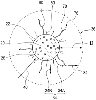
[0083] Figure 5 is an illustrative representation of a system including the
first
and second fluorophores, shown in conjunction with target molecules, according
to the preferred embodiment of the present invention;
[0084] Figure 6 is a graph of various first fluorophore doping percentages in
microbeads against the first fluorescent signal intensity according to the
preferred embodiment of the present invention;
[0085] Figure 7A is an illustrative representation of the system of Figure 5,
shown without the target molecules, marker molecules and second fluorophores;
[0086] Figure 7B is an illustrative representation of the system of Figure 7A
shown in conjunction with the target molecules;
[0087] Figure 7C is an illustrative representation of the system of Figure 7B,
shown in conjunction with the marker molecules and the second fluorophores;
[0088] Figure 8 is a graph of various first fluorescent signal intensities
against
the median second fluorescent signal intensity according to the preferred
embodiment of the present invention, and showing a median fluorescent
emission signal for a molecular FAM dye for comparison purposes;
[0089] Figure 9 is a graph of various median first fluorescent signal
intensities
against the enhancement factor for the second fluorescent signal according to
the
preferred embodiment of the present invention; and
[0090] Figure 10 is an illustrative representation, similar to Figure 5, of an
alternate system including the first and second fluorophores, shown in
conjunction with target molecules, according to an alternate preferred
embodiment of the present invention.
-19-
CA 02693055 2010-01-11
WO 2009/006739 PCT/CA2008/001264
DETAILED DESCRIPTION OF THE PREFERRED EMBODIMENTS
[0091] Referring now to Figures 1-10 of the drawings, there are represented
methods and systems for fluorescent detection of target molecules 60 according
to the present invention. The methods and systems according to the present
invention are adapted to test for the presence of the target molecules 60 in a
test
sample (not shown).
[0092] Generally, and as best seen in Figures 5, 7C and 10, the system
includes
a microbead 20 and biorecognition molecules (BRMs) 50. Each microbead 20
contains first fluorophores 26. The BRMs 50 bind the target molecules 60 (if
present in the test sample), which in turn are bound to marker molecules 70
bearing second fluorophores 76.
[0093] Use of the present invention in biomolecular assays may
advantageously provide for an internal volume of the microbead 20 to be used
as
a localized compartment to hold numerous ones of the first fluorophores 26.
Since, as may be described in considerably greater detail elsewhere herein,
the
first fluorophores 26 are preferably highly customizable quantum dots (QDs),
each microbead 20 may contain thousands, or even millions, of the first
fluorophores 26. Additionally, and as may also be described in considerably
greater detail elsewhere herein, because the QDs may be tailored and/or
customized to have various predetermined and/or selected emission energies,
the first fluorophores 26 may be chosen and embedded within the microbead 20,
such that the fluorescence emission properties of the first fluorophores 26
will
preferably overlap only with another specific fluorophore.
[0094] As best seen in Figures 5, 7A and 10, the BRMs 50 are bound to a
surface 22 of the microbead 20. More specifically, and as best seen in Figure
10,
-20-
CA 02693055 2010-01-11
WO 2009/006739 PCT/CA2008/001264
proximal end portions 52 of the BRMs 50 (being those portions most closely
situated towards the microbead 20) are preferably bound to functional groups
24
provided on the surface 22 of the microbead 20.
[0095] In one preferred embodiment according to the present invention, and
as best seen in Figures 5 and 7A-7C, the BRMs 50 may be provided as one or
more single-stranded biorecognition DNA (BRM-ssDNA) molecules. When the
BRMs 50 are operatively bound to the microbead 20, they together form a
microbead/BRM-ssDNA substrate (as best seen in Figure 7A).
[0096] The microbead/BRM-ssDNA substrate may then preferably be added
to a solution (e.g., a plasma/PCR product). Preferably, the microbead/BRM-
ssDNA substrate will then diffuse through the solution, while searching for
and/or scavenging, via hybridization, the target molecules 60.
[0097] In one preferred embodiment according to the present invention, and
as best seen in Figure 7B, the target molecules 60 may be one or more target
strands of a nucleic acid sequence complementary to at least one of the BRM-
ssDNA molecules. The target molecules 60 operatively bind with the BRMs 50 as
shown in Figure 7B, and have unbound distal end portions 62 - preferably at
least one each. The distal end portions 62 are those portions of the target
molecules 60 which, in an operatively bound configuration (as shown in Figure
7B), are furthest removed from the surface 22 of the microbead 20. When the
target molecules 60 are operatively bound to the microbead/BRM-ssDNA
substrate, they together form a microbead/BRM-ssDNA/target substrate (as best
seen in Figure 7B).
[0098] Subsequently, the marker molecules 70 are preferably added to the
microbead/BRM/target substrate shown in Figure 7B. A second hybridization
-21-
CA 02693055 2010-01-11
WO 2009/006739 PCT/CA2008/001264
reaction will preferably take place to form the test positive end product
shown in
Figure 7C. The second fluorophores 76 are preferably operatively bound to
distal end portions 72 of the marker molecules 70 (as best seen in Figure 7C).
The
distal end portions 72 are those portions of the marker molecules 70 which, in
an
operatively bound configuration (as shown in Figure 7C), are furthest removed
from the surface 22 of the microbead 20. Preferably, the marker molecules 70
operatively bind to the distal end portions 62 of the target molecules 60 (as
best
seen in Figure 7C).
[0099] In an alternate preferred embodiment, and as shown in Figure 10, the
BRMs 50 may be provided as one or more BRM antibody molecules, the target
molecules 60 may be provided as one or more target antigen molecules, and the
marker molecules 70 may be provided as one or more marker antibody
molecules. The BRM antibody molecules and the marker antibody molecules are
operatively bound to the target antigen molecules. The second fluorophores 76
are preferably operatively bound to distal end portions 72 of the marker
antibodies.
[0100] Preferably, and as best seen in Figures 5, 7C and 10, when the target
molecules 60 are present in the test sample (not shown), they operatively
secure
the first fluorophores 26 relative to the second fluorophores 76.
[0101] With further reference to Figure 5, the first fluorophores 26 will be
seen
to operatively emit a first fluorescent signal 34 after absorption of
electromagnetic frequency (EMF) radiation 40. The first fluorescent signal 34
preferably radiates outward from the surface 22 of the microbead 20.
[0102] As best seen in Figure 5, a first incident portion 34A of the first
fluorescent signal 34 is preferably incident upon one or more of the second
-22-
CA 02693055 2010-01-11
WO 2009/006739 PCT/CA2008/001264
fluorophores 76, and a second detectable portion 34B of the first fluorescent
signal 34 radiates further outward from the microbead 20.
[0103] The second fluorophores 76 are adapted for operative absorption of the
first incident portion 34A of the first fluorescent signal 34. After
absorption of
the first incident portion 34A, the second fluorophores 76 operatively emit a
second fluorescent signal 84 (as shown in Figure 5). As may be best
appreciated
from Figure 4, and as may be described in considerably greater detail
elsewhere
herein, the second fluorescent signal 84 is preferably readily distinguishable
from
the first florescent signal 34.
[0104] As shown in Figures 5, 7C and 10, the target molecules 60 secure the
first fluorophores 26 relative to the second fluorophores 76. As such, the
first
incident portion 34A of the first fluorescent signal 34 selectively excites
the
second fluorophore 76, and enhances emission of the second fluorescent signal
84, preferably only if the target molecules 60 are present in the test sample
(not
shown). Without intending to be bound by theory, the aforementioned effect is
believed to occur only when the target molecules 60 are present in the test
sample, since the target molecules 60 operatively secure the first
fluorophores 26
and the second fluorophores 76 relative to each other. In this manner, the
target
molecules 60 enable greater absorption of the first fluorescent signal 34 by
the
second fluorophores 76. This selective excitation of the second fluorophores
76
by the first fluorophores 26 when the target molecules 60 are present in the
test
sample (not shown) is believed - again, without intending to be bound by
theory
- to impart sensitivity, and selectivity, to the assay because unbound second
fluorophores 76 (or molecular dyes of other energies) may show little or no
enhancement of their respective emission spectral signals.
-23-
CA 02693055 2010-01-11
WO 2009/006739 PCT/CA2008/001264
[0105] More particularly, and as best seen in Figure 5, the first fluorophores
26 will preferably emit photons (in the form of the first fluorescent signal
34) in
all directions from the surface 22 of the microbead 20. In this manner,
enhancement of the second fluorescent signal 84 is dependent upon the second
fluorophores 76 being located within a predetermined maximum range (as
indicated generally by dimension "D" in Figure 5) from the first fluorophores
26.
Where, as here, the first fluorophores 26 may be bound substantially at the
surface 22 of the microbead 20, it may be possible to measure the
predetermined
maximum range "D" from the surface 22 of the microbead 20. The
predetermined maximum range "D" defines a region 36 of substantially
unabated radiative flux (or high photon flux) for the first fluorescent signal
34.
In this region 36, similar photon densities (e.g., within 10%) may be observed
at
the surface 22 of the microbead 20 and at the predetermined maximum range
"D" from the surface 22. Without intending to be bound by theory, it is
believed
that the efficiency of the assay is negligibly diminished when the second
fluorophores 76 are bound within the predetermined maximum range "D" from
the surface 22 of the microbead 20. Although not essential to the working of
the
present invention, it may be generally believed that, according to one
preferred
embodiment and by way of non-limiting example only, when the microbead 20
is provided with a diameter of about five micrometers (5 pm), the
predetermined
maximum range "D" may be in the approximate order of about 300 nanometers
(nm).
[0106] In one preferred embodiment, and as best seen in Figures 5 and 7A-7C,
the first fluorophores 26 embedded within the microbead 20 may be provided in
the form of QDs adapted to emit photons centered at about 580 nanometers (nm)
- i.e., generally in the yellow range of the visible light spectrum. These QDs
may
-24-
CA 02693055 2010-01-11
WO 2009/006739 PCT/CA2008/001264
serve as a source of excitation energy for the second fluorophores 76, which
preferably may be provided in the form of a Cyanine-5 (Cy5) molecular dye -
more preferably, a Cyanine-5.5 (Cy5.5) molecular dye - that absorbs yellow
light
strongly and emits photons having a wavelength generally situated towards the
red end of the visible light spectrum.
[0107] As may be appreciated from a consideration of Figure 3, when the
second fluorophores 76 are provided in the form of the Cy5 molecular dye, they
may be excited, inter alia, by incident radiation 90 (e.g., coherent light
from a
laser) having a wavelength of about 635 nanometers (nm) - i.e., provided that
the
incident coherent radiation 90 lies within a second fluorophore absorption
profile
78 (as best seen in Figure 3) characteristic of the Cy5 molecular dye.
Thereafter,
the CY5 molecular dye is adapted to operatively emit the second fluorescent
signal 84. The second fluorescent signal 84 corresponds to a second
fluorophore
emission profile 80 (best seen in Figure 3) characteristic of the Cy5
molecular dye.
Although not essential to the working of the present invention, the intensity
of
the second fluorescent signal 84 emitted by the Cy5 molecular dye may depend
generally upon the amount of the incident radiation 90 absorbed thereby.
[0108] Although not necessary to the operation of the invention, in one
preferred embodiment, the region 36 of substantially unabated radiative flux
(best seen in Figure 5) may be dependent upon the concentration and/or
quantum yield of the QDs bound within the microbead 20. By way of a non-
limiting example only, when microbeads 20 are doped (i) with an arbitrary 100%
QD concentration, and (ii) with a relative 10% QD concentration (i.e., one
tenth of
the QD concentration), the predetermined maximum range "D" for the 100%
QD-doped microbead may be in the approximate order of between about three
and about five (-3 to -5) times higher than that for the 10% QD-doped
- 25 -
CA 02693055 2010-01-11
WO 2009/006739 PCT/CA2008/001264
microbead. In addition, and still by way of example, if the 10% QD-doped
microbead provides for a predetermined maximum range "D" of about 300
nanometers (nm), then the 100% QD-doped microbead might provide for a
predetermined maximum range "D" of about one micrometer (-1 m) or more.
The predetermined maximum range "D" for any particular microbead 20 may be
dependent upon the volume of photon flux within the region 36, and the QD-
doping concentration in the microbead 20.
[0109] Reference will now be made, briefly, to the method of enhancing
fluorescent detection of the target molecules 60 in the test sample (not
shown)
according to one or more preferred embodiments of the present invention. The
method is for use with an irradiating device (not shown) and is, preferably,
for
use with the system shown in Figures 5, 7A-7C and 10. It should, of course, be
appreciated that, according to the present invention, the methods may be
employed independent of the system described elsewhere herein.
[0110] Now, according to the present invention, the method may preferably
include steps (a), (b), (c), (d), (e), (f) and/or (g).
[0111] In step (a), one or more of the first fluorophores 26 (as shown in
Figures 5, 7A-7C and 10) are provided. The first fluorophores 26 are adapted
for
absorption of the EMF radiation 40. The first fluorophores 26 are additionally
adapted for emission of the first fluorescent signal 34 following absorption
of the
EMF radiation 40. As shown in Figure 1, the first fluorophores 26 are
characterized by a first fluorophore absorption profile 28 (substantially
encompassing the wavelength(s) of the EMF radiation 40), and by a first
fluorophore emission profile 30 (substantially corresponding to the first
fluorescent signal 34). The first fluorophore emission profile 30 is itself
-26-
CA 02693055 2010-01-11
WO 2009/006739 PCT/CA2008/001264
preferably characterized by a peak intensity 32 at a wavelength of about 580
nanometers (nm).
[0112] In step (a), and as best seen in Figures 5, 7A and 10, the first
fluorophores 26 are bound by microbead 20. In a preferred embodiment, the
first
fluorophores 26 are provided in the form of the QDs of one or more QD types.
For example, in Figure 10, the QDs are of two different QD types, 26A and 26B.
The intensity of the first spectral signa134 is preferably dependent on the
number
of QDs bound by the microbead 20. The color of the first spectral signal 34 is
preferably dependent upon the size of the QD types, 26A and 26B, bound by the
microbead 20.
[0113] As may be appreciated from a consideration of Figure 1, when the first
fluorophores 76 are provided in the form of the QDs having their peak
intensity
32 at about 580 nanometers (nm), they may be excited, inter alia, by the EMF
radiation 40 at a wavelength of about 488 nanometers (nm) - i.e., provided
that
488 nm lies, as it preferably does, within the first fluorophore absorption
profile
28 characteristic of the first fluorophores 76 (as best seen in Figure 1).
[0114] In step (b), one or more of the second fluorophores 76 (best seen in
Figures 5, 7C and 10) are provided. The second fluorophores 76 are adapted for
absorption of the first incident portion 34A of the first fluorescent signal
34. The
second fluorophores 76 are additionally adapted for emission of the second
fluorescent signal 84 after absorption of the first fluorescent signal 34 (as
may be
best appreciated from a consideration of Figures 2 and 3).
[0115] As best seen in Figure 3, the second fluorophores 76 are characterized
by a second fluorophore absorption profile 78, and by a second fluorophore
emission profile 80 (corresponding to the second fluorescent signal 84). As
-27-
CA 02693055 2010-01-11
WO 2009/006739 PCT/CA2008/001264
shown in Figure 2, the second fluorophore absorption profile 78 substantially
overlaps with the first fluorophore emission profile 30, to define an overlap
region 100. In this context, and for the purposes of this application,
"substantially overlaps" means to a degree sufficient for excitation of the
affected
fluorophores. That is, the first fluorophore emission profile 30 is operative,
in its
overlap region 100 (with the second fluorophore absorption profile 78), to
excite
the second fluorophores 76.
[0116] As shown in Figure 4, the second fluorophore emission profile 80 (and
the second fluorescent signal 84) is distinguishable from the first
fluorophore
emission profile 30 (and the first fluorescent signal 34). Preferably, and as
may
be appreciated from a consideration of Figures 1 and 4, the second fluorophore
emission profile 80 (best seen in Figure 4) is substantially removed from -
i.e., it
does not substantially overlap with - the first fluorophore absorption profile
28
(best seen in Figure 1). As may be described in considerably greater detail
elsewhere herein, the first fluorescent signal 34 and the second fluorescent
signal
84 are operatively detectable within the same visible light spectrum (i.e., if
the
target molecules 60 are present in the test sample).
[0117] Step (c) is preferably performed after step (a). In step (c), the BRMs
50
are provided. Preferably, and as best seen in Figure 10, the BRMs 50 are
adapted
to operatively bind with the microbeads 20 and the target molecules 60 (if
present in the test sample), so as to secure the first fluorophores 26
relative to the
target molecules 60.
[0118] Preferably, step (d) is performed after step (b). In step (d), the
marker
molecules 70 are provided. As best seen in Figure 10, the marker molecules 70
are adapted to operatively bind with the second fluorophores 76 and the target
-28-
CA 02693055 2010-01-11
WO 2009/006739 PCT/CA2008/001264
molecules 60 (if present in the test sample). In this manner, the marker
molecules 70 secure the second fluorophores 76 relative to the target
molecules
60 (if present in the test sample).
[0119] Step (e) is preferably performed after at least one, and preferably
all, of
steps (b) through (d). As may be best appreciated from a consideration of
Figure
10, in step (e), the microbeads 20 containing the first fluorophores 26 are
operatively combined with the BRMs 50, the test sample (not shown) potentially
containing the target molecules 60, the marker molecules 70, and/or the second
fluorophores 76.
[0120] Preferably, step (f) is performed after step (e). In step (f), and as
shown
in Figure 5, at least the first fluorophores 26 are operatively irradiated
with the
EMF radiation 40 via the irradiating device (not shown). Preferably, the
second
fluorophores 76 may also be operatively irradiated with the EMF radiation 40.
[0121] Step (g) is preferably performed after step (f). In step (g), and as
may
be best appreciated from a consideration of Figures 4 and 5, the first
spectral
signal 34 is operatively detected, together with the second spectral signal 84
(if
the target molecules 60 are present in the sample).
[0122] In one preferred embodiment, and with further reference to Figure 10,
the microbeads 20 may be doped with the first fluorophores 26 in the form of
two different QD types, 26A and 26B, to create a specific emission spectrum
("barcode") uniquely identifying a particular one of the microbeads 20 with a
specific set of the BRMs 50 bound thereto. The overall intensity and color of
the
microbead 20 is preferably determined by the amounts, sizes and/or ratios of
the
different QD types, 26A and 26B, used in the doping process.
-29-
CA 02693055 2010-01-11
WO 2009/006739 PCT/CA2008/001264
[0123] Figure 6 shows the median intensity of emitted wavelengths produced
from a series of synthetic microbeads 20 in which the percentage doping with
the
QDs (i.e., the first fluorophores 26) was varied between about 10% and about
100% of a stock concentrated QD solution. In Figure 6, the average emission
intensity for the series of microbead 20 samples is displayed as measured on a
FACSCalibur flow cytometer.
[0124] In one preferred embodiment according to the present invention, the
microbeads 20 are doped with the QDs (i.e., the first fluorophores 26) which
emit
the first fluorescent signal 34 with a wavelength centered roughly about 580
nanometers (nm) - such that these microbeads may alternately herein be
referred
to as QD580 doped microbeads 20. The QD580 doped microbeads 20 may be
used, for example, as a substrate in a sandwich nucleic acid or genomic assay
(as
shown in Figures 5 and 7A-7C) or in a sandwich immunoassay according to one
or more preferred methods of the present invention. Preferably, the QDs (i.e.,
the first fluorophores 26) are thus operative to sensitize and/or enhance the
emission intensity for the second fluorophores 76 (e.g., Cy5 molecular dyes).
[0125] Preferably, and as may be best appreciated from a consideration of
Figure 1, a 488 nm laser (not shown) may be used to excite the QD580 doped
microbeads 20. As shown in Figure 5, the QD580 doped microbeads 20 may be
bound to the target molecules 60, which are in turn bound to the marker DNA
molecules (i.e., the marker molecules 70). Each of the marker DNA molecules
may preferably bear one or more Cy5.5 molecular dyes (DNA-Cy5.5) which
provide for an emission towards the red end of the visible light spectrum.
Figure
8 graphs the median dye intensity for the Cy5.5 molecular dyes in conjunction
with the median QD intensity of the QD580 doped microbeads.
-30-
CA 02693055 2010-01-11
WO 2009/006739 PCT/CA2008/001264
[0126] On excitation with the 488 nm laser, the QDs are selectively excited,
and the DNA-Cy5.5 emission is enhanced (with a concomitant increase in its
median QD intensity), as may be appreciated from a consideration of Figure S.
[0127] Compared against this reference line, Figure 8 also graphs the median
dye intensity for FAM molecular dyes (DNA-FAM) bound in conjunction with
the marker DNA molecules, the target molecules 60, and the QD580 doped
microbeads. The FAM molecular dyes provide for an emission substantially
within the green range of the visible light spectrum. Perhaps notably, the FAM
molecular dyes are situated generally in the blue (higher energy) direction
from
the generally yellow-emitting QD580 doped microbeads.
[0128] In Figure 8, the intensity of the DNA-Cy5.5 emission is compared to
the intensity of the DNA-FAM emission over a range of median QD intensities.
As may be appreciated from a consideration of Figure 8, the represented data
fails to demonstrate a corresponding enhancement and excitation of surface-
bound DNA-FAM by QD580-doped microbeads.
[0129] The prior art may heretofore have been largely based on the use of
second fluorophores 76 situated generally towards the "blue" end of the
spectrum relative to the QDs (i.e., the first fluorophores 26). As such, in
the prior
art, the second fluorophores 76 may have been effectively quenched, with the
second fluorescent signa184 being diminished by the first fluorophore
absorption
profile 28 and/or the first fluorophore emission profile 30 (shown in Figure
1) of
the QD-doped microbead 20.
[0130] In order to provide for enhancement of the second fluorescence signal
84 (and not the previously known opposite quenching effect), it may be
generally
thought preferable - though perhaps not essential to the working of the
present
-31-
CA 02693055 2010-01-11
WO 2009/006739 PCT/CA2008/001264
invention - for the second fluorophore emission profile 80 (and thus the
second
fluorescent signal 84 emitted by the second fluorophores 76) to be located
towards the "red" end of the visible light spectrum - i.e., relative to the
first
fluorescent signal 34 emitted by the first fluorophores 26. It may also be
preferable for the first fluorophore emission profile 30 (and thus the first
fluorescent signal 34 of the first fluorophores 26) to be located in the
yellow
range of the visible light spectrum.
[0131] It may be appreciated that the graph shown in Figure 9 illustrates the
second fluorophores 76 (preferably, the Cy5 molecular dyes) as being adapted
to
emit the enhanced second fluorescent signal 84 as a function of QD-doping
within the microbeads 20. Preferably, the Cy5 emission intensity may increase
to
become in the approximate order of over about 200 times brighter when
compared to a blank (non-doped) microbead 20 sample. (A lack of controls -
e.g., blank microbeads - in prior experiments may have made their results
and/or
procedures substantially unsuitable for any testing or exploitation of the
enhancement effect described herein.) Although not essential to the working of
the present invention, it may be believed that the intensity generated by use
of
the microbead 20 emission, alone, may be about as great as (or greater than)
that
generated by use of the laser alone.
[0132] It is believed that overall fluorescent detection sensitivity may be
substantially increased by enhancement of the second fluorophores 76, thus
enabling the second fluorophores 76 (whether they be dye molecules or QDs) to
be used in conjunction with larger and more intense emission molecules, such
as
the microbeads 20 referred to herein.
-32-
CA 02693055 2010-01-11
WO 2009/006739 PCT/CA2008/001264
[0133] Other modifications and alterations may be used in the design and
manufacture of other embodiments according to the present invention without
departing from the spirit and scope of the invention, which, is limited only
by
the accompanying claims of this application. For example, while the above
method and system have, in one preferred embodiment, been presented in the
context of an immunoassay and a genomic assay, the method and system may be
equally applicable to other types of assays (and/or for the detection of other
types
of target molecules, possibly in other types of test samples).
[0134] Additionally, the method and system according to the present
invention may preferably be used for a variety of in vitro biomolecular assays
including genomic and/or proteomic identification of markers for infectious
diseases, cancer, cystic fibrosis and other human veterinary or environmental
aliments. Similarly, the method and system according to the present invention
may preferably be used for detection of cardiac symptoms and/or detection of
biomarkers for cardiac conditions and/or predispositions. The method and
system according to the present invention are also preferably adapted for use
in
medical imaging and other in vivo applications.
[0135] In view of all of the foregoing, it is perhaps worthwhile to once again
note that the foregoing description has been presented for the purpose of
illustration and is not intended to be exhaustive or to limit the invention to
the
precise form disclosed. Many further modifications and/or variations are
possible in light of the teachings herein, as may be apparent to those skilled
in
the art. It is intended that the scope of the present invention be limited not
by
this description but only by the accompanying claims.
-33-