Note: Descriptions are shown in the official language in which they were submitted.
CA 02693123 2010-01-15
WO 2009/015672 PCT/EP2007/006771
-1-
Carbon shafted reaming device
Field of the Invention
The present invention relates to a reaming device, and in particular to a
reaming
device having a shaft with a carbon fibre reinforced structure.
Background of the Invention
Intramedullary nailing is the method of choice for the fixation of fractures
in long
bones, in particular in long extremities. To have a full access to the
intramedullary
channel, a shaft of a reamer has to be flexible enough in a bending direction
to
bypass soft tissue and bone curvature, and has also to be rigid enough to
convey
torsion to the reamer head. Prior art reaming devices have a shaft design
consisting
of a helix in which residues can be trapped during the reaming procedure, so
that the
cleaning of the reaming device in hospitals prior to the next usage is
complicated, in
particular for a sterilisation process. The adequate cleaning of the
instrument in
hospitals demands a high effort and takes a lot of time. Further, some
hospitals are
not prepared to clean such critical devices because of the high effort
involved.
In some prior art reaming devices, a helix shaft is replaced by a shaft made
of so
called nitinol, which is a material having a high degree of elasticity (super
elasticity)
to provide enough flexibility. Nitinol is an akronym for NIckel TItanium Naval
Ordnance Laboratory. Nitinol is the inter-metallic phase NiTi having a regular
cubic
crystal structure being different of the structure of titanium or nickel.
Nitinol
comprises about 55% nickel and about 45% titanium. Owing to the fact that the
nitinol shaft is made of a single tube, the cleaning effort in the hospital is
less
exhausting. However, recent investigations have shown that the nitinol
material has
a catastrophic failure mode. In particular, some reports have pointed out that
some
breakages in multiple fragments of the nitinol shaft occurred during the
reaming
CA 02693123 2010-01-15
WO 2009/015672 PCT/EP2007/006771
-2-
process during the operation process in hospitals. Further, the nitinol
material is a
very expensive material.
From US 2007/0015107, a root canal instrument having an abrasive coating and
method for the production thereof is known, wherein the described root canal
instrument has a core of a flexible elastic material having a shape memory,
wherein
the core furthermore has a coating with abrasive particles, wherein the core
is made
from a nickel-titanium alloy or from a plastic material, e.g. carbon fibre
reinforced
plastics material.
CH 668690 describes a probe electrode cable for medical purposes, e.g. electro
cardiogram test, using carbon fibre impregnated plastic insulating coating as
a cover
with a lead coupled to the test equipment.
Summary of the Invention
It may be seen as an object of the present invention to provide a more
reliable
reaming device.
The object of the present invention is solved by the subject matter of the
independent
Claims. Advantageous embodiments thereof are incorporated in the dependent
Claims.
According to an exemplary embodiment of the invention, a reaming device
comprises a rod element, an interface element and a connecting agent, wherein
the
rod element comprises a first connecting portion having a carbon fibre
reinforced
structure, wherein the interface element comprises a second connecting
portion,
wherein the first connecting portion and the second connecting portion are
CA 02693123 2010-01-15
WO 2009/015672 PCT/EP2007/006771
-3-
concentrically arranged to each other, and wherein the connecting agent is
interposed
between the first connecting portion and the second connecting portion.
Thus, a reaming device is provided, which does not have the cleaning problem
of the
spiral reamer of the prior art, and providing at the same time a more robust
material
due to the carbon fibre reinforced structure of the rod element. Further, the
rod
element having a carbon fibre reinforced structure portion is cheaper than the
nitinol
material of the prior art, and further much more robust. The connecting agent
provides a reliable connection between the rod element and the interface
element.
The interface element may be a coupling element being capable of carrying a
reaming tool of a reaming device, but may also be a coupling to a reaming
drive of
the reaming device. In other words, the interface element may be a coupling on
both
sides of the reaming device, on the drive input side and the drive output side
of the
reaming device. The connecting portions, i.e. the first connecting portion and
the
second connecting portion may be particularly prepared for receiving the
connecting
agent in order to provide a reliable connection between the rod element and
the
interface element.
According to an exemplary embodiment of the invention, the first connecting
portion
is provided on an outer surface of the rod element, and the second connecting
portion
is provided on an inner surface of the interface element.
Thus, the connection portion of the rod will be at least partially surrounded
by the
interface element, so that the interface element covers the connecting portion
of the
rod element. However, the first connecting portion may also be provided on an
inner
surface of the rod element, and the second connecting portion may be provided
on an
outer surface of the interface element. In this case, the rod element should
be
provided with a hole, into which the interface element may be inserted, in
particular
CA 02693123 2010-01-15
WO 2009/015672 PCT/EP2007/006771
-4-
into which the second connecting portion of the interface element may be
inserted.
In both of the previously describe cases, the transit from the rod element to
the
interface element or vice versa may be designed as a smooth transit in order
to avoid
portions bearing the risk of trapping ablated tissue, which may be problematic
with
respect to the cleaning process of the reaming device.
According to an exemplary embodiment of the invention, the first connecting
portion
comprises a first recess, wherein the connecting agent engages into the first
recess.
Providing the first connecting portion of the rod element with a recess
provides an
improved force transmission during the operation of the reaming device, since
the
force transmission is not limited to the share forces affecting between the
connecting
agent and the surface of the rod element on the first connecting portion.
Moreover,
the forces may also be transmitted by the interaction between a protrusion of
the
connecting agent engaging into the recess and the recess itself.
According to an exemplary embodiment of the invention, the first portion
comprises
a second recess, wherein the first recess and the second recess are displaced
to each
other in an axial direction of the rod element.
The provision of a second recess being displaced with respect to the first
recess in an
axial direction allows to form a further protrusion of the connecting agent so
that a
force distribution may be improved. The provision of a displacement into an
axial
direction further distributes the force impact locations to different axial
positions, so
that the weakening of the rod element in the area of the first connecting
portion may
be limited in order to avoid a break of the rod element.
CA 02693123 2010-01-15
WO 2009/015672 PCT/EP2007/006771
-5-
According to an exemplary embodiment of the invention, the first portion
comprises
a third recess, wherein the first recess and the third recess are displaced to
each other
in a circumferential direction of the rod element.
The provision of several recesses being displaced in a circumferential
direction may
further improve the distribution of the transmitting forces in order to form
an
improved contact between the rod element and the interface element.
According to an exemplary embodiment of the invention, the interface element,
in
particular the second connection portion, comprises a fourth recess, wherein
the
connecting agent engages into the fourth recess.
The provision of a recess in the interface element provides also an improved
force
transmission between the connecting agent and the respective interface
element.
According to an exemplary embodiment of the invention, the interface element,
in
particular the second connecting portion comprises a fifth recess, wherein the
fourth
recess and the fifth recess are displaced in an axial direction of the
interface element.
The displacement of the fourth and fifth recess provides an improved force
distribution in order to improved the force transmission between the
connecting
agent and the interface element. The provision of an axial displacement of the
recesses may avoid a weakened structure of the interface element and to
distribute
the force transmission to a plurality of axially distributed locations.
According to an exemplary embodiment of the invention, the interface element
comprises a sixth recess, wherein the fourth recess and the sixth recess are
displaced
in a circumferential direction of the interface element.
CA 02693123 2010-01-15
WO 2009/015672 PCT/EP2007/006771
-6-
The provision of several recesses displaced in a circumferential direction may
provide an improved geometry with respect to the force transmission between
the
connecting agent and the interface element.
It should be noted that a plurality of recesses may be provided which are
displaced in
both directions, an axial direction and a circumferential direction at the
same time.
Further, the number of recesses is not limited and may be provided according
to the
respective need of the application. Further, it should be noted that the
connecting
agent may engage into the several recesses, in particular also into the
second, third,
fifth and sixth recess, in order to improve the force transmission between the
rod
element and the interface element via the connecting agent. It should be
further
noted, that the recesses in the rod element and the recesses in the interfaces
may at
least partially correspond to each other with respect to the location of
recesses, so
that the recesses may face to each other. Thus, the respectively engaging
portions of
the connecting agent may form a kind of bolting connection between the rod
element
and the respective interface element. Further, it should be noted that, for
example, the
third recess may be provided even if there is no second recess, and that a
fourth
recess may be provided even if there is no first, second or third recess, and
so forth.
In other words, the recesses may be provided arbitrarily with respect to the
need of
the respective application.
According to an exemplary embodiment of the invention, at least one of the
recesses
is formed in a shape of a spherical hole.
The provision of a spherical hole provides the advantage over a cylindrical
hole, in
that the spherical hole does not provide any sharp chamfer or notch, which
sharp
CA 02693123 2010-01-15
WO 2009/015672 PCT/EP2007/006771
-7-
chamfer or notch bears the risk of a breakage of the rod element. Thus, by
means of
a recess in form of a spherical hole a sharp notch or a sharp chamfer may be
avoided.
According to an exemplary embodiment of the invention, at least one of the
recesses
is formed in a shape of a groove, which groove extends into a longitudinal
direction
of the rod element.
A groove extending in an axial direction has a larger cross-section than a
hole, and
therefore may provide an improved force transfer between the respective
elements.
It should be noted that the groove may have a cross-section of a half circuit
in order
to avoid sharp notches or sharp chamfers in order to avoid an unintended
breakage of
the respective elements.
According to an exemplary embodiment of the invention, at least one recess
forms a
through-hole in the interface element.
The provision of a through-hole is much easier to manufacture than a blind
hole, in
particular when providing such a hole into the inner wall portion of an axial
directed
bore hole.
According to an exemplary embodiment of the invention, the interface element
is
adapted to couple a reaming tool to the rod element.
It should be noted that the interface element may also be adapted to couple a
drive to
the rod element. With providing two interface elements, a first interface
element for
coupling a reaming tool and a second interface element as a coupling for a
drive, the
design, in particular the geometry of the connecting agent of both connections
between the rod element and the interface element on the reaming tool side and
the
CA 02693123 2010-01-15
WO 2009/015672 PCT/EP2007/006771
-8-
interface element on the drive side may be designed such that the connecting
agent
provides a predetermined breaking point on the drive side. Thus, if the
driving
forces extend over the capability of the intended limited force transmission
of the
connection between the rod element and the respective interface elements, the
predetermined breaking point will be provided on the side of the driving
interface
element, so that during the operation procedure on or in a human body, the
breakage
takes place outside the human body, so that no residues of the reaming device
remain
in the human body. The predetermined breaking point may be provided by, for
example, by a reduced number of recesses on the drive side with respect to the
reaming tool side.
According to an exemplary embodiment of the invention, the rod element
comprises
a first conduit extending in a substantially longitudinal direction of the rod
element.
The provision of a conduit within the rod element provides the possibility to
provide
a medical effective agent from the outside to the reaming tool side of the rod
element
and the respective coupled interface element. On the other hand, the conduit
in the
rod element provides the possibility to remove the ablated tissue from the
reaming
tool side to the outside.
According to an exemplary embodiment of the invention, the interface element
comprises a second conduit, which conduit being connected to the first conduit
of the
rod element.
Thus, the second conduit in the interface element corresponds to the first
conduit of
the rod element, so that the material being transported through the conduit
may be
transferred from the interface element to the rod element and vice versa. A
conduit
may be provided for both kinds of interface elements, the interface element as
a
CA 02693123 2010-01-15
WO 2009/015672 PCT/EP2007/006771
-9-
coupling for a reaming tool and the interface element as a coupling to the
drive. It
should be noted that the outlet of the conduit of the interface elements may
also be
provided on the outer wall side, i.e. on the lateral portion of the interface
element, in
particular when the provision of an agent is desired or the removal of tissue
is
desired.
According to an exemplary embodiment of the invention, the rod element is made
from a carbon fibre composite (CFC).
According to an exemplary embodiment of the invention, the carbon fibres are
wound in at least a first layer and a second layer, wherein the direction of
the first
layer and the second layer are inclined at an angle of substantially
plus/minus 45 ,
respectively, with respect to a longitudinal axis of the rod element.
Thus, the carbon fibres are optimised to have a maximum torsional resistance
together with a low bending resistance. It should be noted that also different
inclination angles of the direction may be provided, if there is a need to
adapt the
torsional resistance and the bending resistance as well as the ratio of the
torsional
resistance and the bending resistance.
According to an exemplary embodiment of the invention, the connecting agent is
an
adhesive.
The adhesive provides a reliable connection between the rod element and the
interface element. It should be noted that for a reaming device an adhesive
should be
used which is compatible with respect to the human body. An appropriate
adhesive
should be an adhesive which provides a reliable connection and a bio-
compatibility
at the same.
CA 02693123 2010-01-15
WO 2009/015672 PCT/EP2007/006771
-10-
According to an exemplary embodiment of the invention, the connecting agent is
a
thermal hardening adhesive.
A thermal hardening adhesive provides the possibility of a longer
manufacturing
period, so that when obtaining the correct positioning of the rod element and
the
interface element to each other, the hardening process may be started,
initiated by a
heat impact.
According to an exemplary embodiment of the invention, the connecting agent is
a
multiple component epoxy resin.
Multiple component epoxy resins provide a reliable and strong connection due
to the
chemical process starting when mixing the multiple components of the epoxy
resin
or when impacting a heat. Thus, an ageing process or an early binding of the
adhesive may be avoided.
According to an exemplary embodiment of the invention, the connecting agent is
a
third layer of carbon fibre, which third layer is wound around the first layer
and the
second layer, wherein the third layer is wound into a circumferential
direction of the
rod element. It should be noted that the first layer and the second layer of
the carbon
fibre do not have to be separated, and may also constitute an interwoven
structure.
However, if the carbon fibres are inclined with respect to a solely
circumferential
direction, the stability of the structure may be weakened, so that the winding
of a
third carbon fibre layer in a circumferential direction provides a sufficient
stable
structure, in particular when the third carbon layer serves as a connecting
agent. The
third carbon layer may serve as a connecting agent in cases, the rod element
and the
CA 02693123 2010-01-15
WO 2009/015672 PCT/EP2007/006771
-11-
interface element are connected by a press fitting, which does not need an
adhesive
for a reliable connection between the rod element and the interface element.
It should be noted that the above features may also be combined. The
combination
of the above features may also lead to synergetic effects, even if not
explicitly
described in detail.
These and other aspects of the present invention will become apparent from and
elucidated with reference to the embodiments described hereinafter.
Brief Description of the Drawings
Exemplary embodiments of the present invention will be described in the
following
with reference to the following drawings.
Fig. 1 illustrates an exemplary embodiment of a rod element, a connecting
agent and
an interface element, which interface element may serve as a coupling for a
reaming
tool.
Fig. 2 illustrates an exemplary embodiment of the rod element, the connecting
agent
and an interface element, which interface element may serve as a coupling to a
drive.
Figs. 3a and 3b illustrate the separated components of a reaming device
according to
an exemplary embodiment.
Figs. 4a and 4b illustrate the mounted components of Figs. 3a and 3b according
to an
exemplary embodiment.
CA 02693123 2010-01-15
WO 2009/015672 PCT/EP2007/006771
-12-
Figs. 5a, 5b, 5c and 5d illustrate a rod element having a connecting portion
according
to an exemplary embodiment.
Figs. 6a, 6b, 6c and 6d illustrate a rod element having a connection portion
according
to an exemplary embodiment.
Figs. 7a, 7b, 7c, 7d, 7e and 7f illustrate an interface element serving as a
coupling for
a reaming tool according to an exemplary embodiment.
Figs. 8a, 8b, 8c and 8d illustrate an interface element serving as a coupling
to a drive
according to an exemplary embodiment.
Figs. 9a, 9b, 9c and 9d illustrate an interface element serving as a coupling
to a drive
according to an exemplary embodiment.
Detailed Description of Exemplary Embodiments
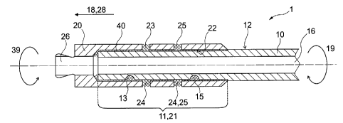
Fig. 1 illustrates an exemplary embodiment of the coupling of the rod element
10 and
the interface element 20 by means of a connecting agent 40. The rod element 10
may be provided with a conduit 16. The rod element according to the
illustrated
embodiment comprises a first recess 13 and a third recess 15, which are formed
as
spherical holes. In this embodiment, the holes are blind holes, so that the
sealing of
the conduit 16 may be upheld in the region of the holes or recesses. It should
be
noted the recesses may also be through holes . The rod element 10 is provided
with a
connection portion 11. The interface element 20 in this embodiment is provided
with
a fourth, fifth and sixth recess 23, 24, 25. The recesses may be provided on
displaced locations with respect to the longitudinal axis 18 of the rod
element, which
corresponds to the longitudinal axis of the interface element 28 in this
embodiment.
CA 02693123 2010-01-15
WO 2009/015672 PCT/EP2007/006771
- 13-
As can be seen, recess 23 is displaced in the longitudinal direction 28 to the
recess
25. The same is valid for the recesses 13 and 15, which are displaced to each
other
with respect to the longitudinal axis 18 of the rod element 10. The recesses
of the
interface element 20 are provided as bore holes. It should be noted that the
recesses
may also be displaced with respect to a circumferential direction of the
interface
element 39, as can be seen from the recesses 23 and 24, which are displaced by
about
1800, however any other degree of displacement may be applied according to
need.
Although Fig. 1 does not illustrate the circumferential displacement of
recesses of the
rod element 10 into a circumferential direction 19, it should be noted that
also
recesses may be provided, which are displaced with respect to the
circumferential
direction 19 of the rod element 10. The interface element 20 is provided with
a
second connecting portion 21 which corresponds to the first connecting portion
11 of
the rod element 10. A connecting agent 40 is provided between the
concentrically
arranged first connecting portion 11 of the rod element 10 and the second
connecting
portion 21 of the interfacing element 20. In the illustrated embodiment, the
connecting agent 40 engages into the recesses 13, 15, 23, 24 and 25, so that
an
improved force transfer between the rod element 10 and the interface element
20
may be provided. However, it should be noted that if the force transfer
between the
rod element 10 and the interface element 20 is sufficient, the contact agent
40 does
not have to engage into the recesses, even if the recesses are provided. In
this case, it
should be noted, that the recesses may also be left out.
Fig. 2 illustrates a reaming device 1 having a rod element 10 and an interface
element 30, wherein the rod element 10 and the interface element 30 are
concentrically arranged at least in the first connecting portion 11 and the
second
connecting portion 31. Fig. 2 illustrates recesses on the outer surface 12 of
the rod
element 10, which are formed as grooves extending into the longitudinal
direction 18
of the rod element 10. The longitudinal direction 18 of the rod element 10 and
the
CA 02693123 2010-01-15
WO 2009/015672 PCT/EP2007/006771
-14-
longitudinal direction 38 of the interface element 30 correspond to each other
in the
present embodiment. The recesses 13, 14 and 15 provided on the surface 12 of
the
rod element 10 are displaced with respect to the longitudinal direction 18 of
the rod
element 10, as well as they are displaced with respect to the circumferential
direction
19 of the rod element 10. The rod element 10 and the interface element 30 are
concentrically arranged in the first connecting portion 11 of the rod element
10 and
the second connecting portion 31 of the interface element 30. The illustrated
rod
element 10 comprises a conduit 16 which corresponds to a conduit 36 of the
interface
element 30, so that a transport of a medical agent or tissue may be carried
out. A
connecting agent 40 is provided between the rod element 10 and the interface
element 30, wherein the connecting agent 40 may engage into the recesses 13,
14 and
15. Thus, an improved force transfer may take place between the interface
element
30 and the rod element 10.
If, for example, leaving out the fourth, fifth and sixth recess on the driving
side
interface element 30 of Fig. 2 a predetermined breaking point may be provided,
since
the force transfer between the interface element 30 and the rod element 10 may
be
limited, so that if extending the applied forces, the connection by the
connecting
agent 40 between the rod element 10 and the interface element 30 intendedly
will
break, so that a break of the rod element 10 as such and a break between the
rod
element 10 and the reaming tool sided interface element 20 of Fig. 1 may be
avoided,
so that the predetermined breaking point is provided outside the human body
for
every operation situation.
Fig. 3a and Fig. 3b illustrate as a side view (Fig. 3a) and a cross-sectional
view (Fig.
3b) of the several components of a reaming device 1 having a rod element 10
and
two interface elements 20, 30. The connecting agent 40 is not illustrated in
Figs. 3a
and 3b. As can be seen from Fig. 3b, the provision of a conduit in all
components
CA 02693123 2010-01-15
WO 2009/015672 PCT/EP2007/006771
-15-
10, 20, 30 provides a connection to deliver any medical agent or to remove
tissue
from the reaming tool (not shown).
Fig. 4a and Fig. 4b illustrate the assembled reaming device 1 having a rod
element 10
and two interface elements 20, 30. As can be seen from the cross-sectional
view in
Fig. 4b, the rod element 10 and the interface elements 20, 30 are
concentrically
arranged such that the connecting portion of the interface elements 20, 30
cover the
respective connecting portions of the rod element 10.
Figs. 5a, 5b, 5c and 5d illustrate the rod element 10, and in particular the
connecting
portion 11 of the rod element 10. In the connecting portion 11 of the rod
element 10,
there may be provided recesses 13, 14 and 15, wherein the recesses may be
displaced
with respect to the longitudinal direction, as can be seen in Fig. 5a, or may
be
displaced in a circumferential direction, as can be seen from Fig. 5b, which
is rotated
by 90 over the illustration of Fig. 5a.
Further, Fig. 5a illustrates an exemplary embodiment of the carbon fibre
layers,
wherein the first and second carbon fibre layer 17a, 17b may be provided as an
interwoven structure, as can be seen from Fig. 5b. The interwoven structure
may be
surrounded by a third layer 17c, which is wound in the circumferential
direction of
the rod element 10. The circumferential winding in particular is relevant if
applying
a press fitting between the interface elements 20, 30 and the rod element 10.
Fig. 5c
illustrates a cross-sectional view along the cut A-A, wherein Fig. 5d
illustrates an
enlarged cross-sectional view of Fig. 5c showing some more details. Fig. 5d
illustrates an exemplary embodiment of a recess 13, 14, 15, which is formed as
a
spherical hole. It should be noted that a spherical hole should also be
understood as a
hole formed by a part of a sphere, as can be seen from Fig. 5d. Further, the
recesses
CA 02693123 2010-01-15
WO 2009/015672 PCT/EP2007/006771
-16-
13, 14, 15, 23, 24, 25, 33, 34, 35 may have any other form, e.g. a cylindrical
form or
a form without sharp notches. This however is not limited to spherical holes.
Figs. 6a, 6b, 6c and 6d illustrate a further exemplary embodiment,
illustrating
recesses 13, 14, 15 on the surface side of the rod element 10, which recesses
are
formed as grooves into a longitudinal direction of the rod element 10. The
grooves
may be displaced with respect to the longitudinal axis of the rod element 10,
as can
be seen from Fig. 6b, as well as displaced into a circumferential direction,
as can be
seen from Fig. 6a, which illustrates a view of the rod element of Fig. 6b
being rotated
by 90 . Fig. 6c illustrates a cross-sectional view of Fig. 6a, and Fig. 6d
illustrates an
enlarged cross-sectional view of the rod element shown in Fig. 6c. As can be
seen
from Fig. 6d, the recesses 13, 14 and 15 may have a cross-section in form of a
circle
sector in order to avoid sharp notches or sharp chamfers in order to avoid a
damage
of the rod element 10 when transferring forces.
Fig. 6a illustrates further a first layer 17a and a second layer 17b of the
carbon fibres,
wherein the carbon fibres in the embodiment of Fig. 6a are wound in separate
layers.
It should be noted that also any other arrangement of the first and second
layer 17a
and 17b may be provided, in particular any other woven pattern may be used,
where
it is appropriate and necessary for the respective application according to
need. The
number of layers is however not limited to a first and second layer, and may
be also a
multi layer structure.
Figs. 7a, 7b, 7c, 7d, 7e and 7f illustrate an interface element 20, which is
adapted to
couple a reaming tool. The coupling of the reaming tool takes place at the
head of
the interface element 20, a detail of which is illustrated in Fig. 7e. The
second
connecting portion 21 of the interface element 20 may be provided with a
plurality of
recesses 13, 14 and 15, which may be displaced into an axial direction as well
as a
CA 02693123 2010-01-15
WO 2009/015672 PCT/EP2007/006771
-17-
circumferential direction, as can be seen from Fig. 7a and the corresponding
cross-
sectional view of Fig. 7b. The interface element 20 may also be provided with
a
conduit 26 which may provide a connection between the conduit of a rod element
16
(not shown in any of the Figs. 7a, 7b, 7c, 7d and 7f) to a conduit of a
reaming tool
(also not shown).
Fig. 7c illustrates a top view of the illustration of Fig. 7a. Fig. 7d
illustrates a cross-
sectional view of the interface element 20, rotated by 90 over the
illustration of Fig.
7b. Fig. 7f illustrates a three-dimensional view of the interface element 20.
Figs. 8a, 8b, 8c and 8d illustrate a further exemplary embodiment of an
interface
element, however this interface element is adapted to couple a drive for
driving the
reaming device. Fig. 8a illustrates a side view of the exemplary interface
element 30.
Fig. 8c illustrates a top view of the interface element 30 shown in Fig. 8a.
Fig. 8b
illustrates a cross-sectional view of the interface element 30 of Fig. 8a,
wherein the
interface element 30 is also provided with a conduit 36 into a longitudinal
direction.
The connecting portion 31 comprises a plurality of recesses 33, 34, 35, which
recesses may be provided as blind holes as well as through-holes (not shown).
The
recesses may be formed as cylindrical holes as well as spherical holes (not
shown).
The recesses 33, 34, 35 may be provided on the inner surface 32 of a bore
hole,
which bore hole is adapted to receive the connecting portion 11 of the rod
element
10. Fig. 8d illustrates a three-dimensional view of the interface element 30
according
to an exemplary embodiment.
Figs. 9a, 9b, 9c and 9d illustrate a further exemplary embodiment of an
interface
element 30, which is adapted to be coupled to a drive. Fig. 9a illustrates a
side view,
Fig. 9c illustrates an enlarged top view, and Fig. 9b illustrates a cross-
sectional view
CA 02693123 2011-11-14
-18-
of the interface element 30. Fig. 9d illustrates a three-dimensional view of
the
interface element 30.
The interface elements of Figs. 8a, 8b, 8c and 8d differ from the interface
elements of
Figs. 9a, 9b, 9c and 9d in that they provide a different coupling geometry for
a drive,
which may be specified with respect to the supplier of the drive unit. Thus,
it should be
noted that the design of the coupling geometry may be modified with respect to
the drive
unit to be coupled to the interface element 30.
It should be noted that the terms `a' or `an' do not exclude a plurality. Also
elements
described in association with the different embodiments may be combined.