Note: Descriptions are shown in the official language in which they were submitted.
CA 02693535 2010-02-18
UTILITY TRAILER
FIELD OF THE INVENTION
[0001] The present invention relates to the field of utility trailers, in
particular, utility trailers
with rear pivotable gates.
BACKGROUND OF THE INVENTION
[0002] Conventional utility trailers with pivotable rear gates often have
generally C-shaped or
U-shaped support frames (when viewed in top plan). Such support frames are
usually built up of
several structural members in the nature of longitudinal side members and
cross-members and
have welded joints at the corners where the longitudinal side members meet the
front cross-
member. The assembly of such frames can be labour-intensive and may require
extensive
welding. Moreover, from a structural design perspective, the formation of
welded joints at the
corners of the support frame tends not to be desirable, as the corners tend to
be subjected to
significant bending moments and shear stresses, often resulting in the failure
of these welded
joints. When such frames are fabricated from tubular hollow sections having
circular profiles,
these problems may be further exacerbated by the fact that welding arcuate
surfaces tends to be
more complicated and tends to require the implementation of special measures
(for instance, the
formation of arcuate notches - corresponding to curvature in the hollow
sections - at the ends of
some of the hollow sections where the welding connection is to be made), so as
to ensure the
weld is properly formed.
[0003] In light of the foregoing, there is a real need for a utility trailer
exhibiting improved
resistance to bending moments and shear stresses at the corners of the support
frame. Preferably,
such a utility trailer would be lightweight, robust and less prone to
structural failures in its
support frame. It would be further desirable, if the manufacturing of such a
utility trailer could be
simplified by reducing the welding required.
SUMMARY OF THE INVENTION
[0004] According to a broad aspect of an embodiment of the present invention,
there is
provided a utility trailer. The utility trailer includes a trailer bed
supported on wheels for rolling
DM TOR/263490-00001/3474867.1
CA 02693535 2010-02-18
-2-
motion on the ground. The trailer bed has a floor on which cargo may be placed
and a support
frame for carrying the floor. The support frame includes a front end; a rear
end; and a pair of
spaced apart, upper and lower, bent U-shaped members extending between the
front and rear
ends of the support frame. Each U-shaped member is fabricated from a hollow
section having
one of a square cross-section and a rectangular cross-section. The support
frame further includes
a plurality of spaced apart, substantially upright struts extending between,
and connecting the
upper and lower bent U-shaped members to each other and a plurality of spaced
apart cross-
members connecting portions of the lower bent U-shaped member to each other.
The utility
trailer is also provided with a gate pivotally mounted to rear end of the
support frame. The gate is
movable between a substantially upright position relative to the floor of the
trailer bed and a
lowered, in-use position.
[0005] In a further feature, the floor is supported on the lower bent U-shaped
member and the
plurality of cross-members.
[0006] In another feature, at least one of the upper and lower bent U-shaped
members has a
square cross-section. In an additional feature, both the upper and lower bent
U-shaped members
have a square cross-section. Alternatively, at least one of the bent U-shaped
members has a
rectangular cross-section or both the upper and lower bent U-shaped members
could have a
rectangular cross-section. In a further feature, the upper bent U-shaped
member has a first cross-
sectional area and the lower bent U-shaped member has a second cross-sectional
area. The first
cross-section area is smaller than or equal to the second cross-sectional
area.
[0007] In yet another feature, each of the upper and lower bent U-shaped
members includes a
back portion and two opposed, generally parallel, first and second arm
portions. The arm
portions of each upper and lower bent U-shaped members are joined to the
respective back
portions of each upper and lower bent U-shaped members. Each of the upper and
lower bent U-
shaped members are formed with a first radiused corner portion whereat the
back portion of each
upper and lower bent U-shaped members transitions to become the respective
first arm portion of
each upper and lower bent U-shaped members, and a second radiused corner
portion whereat the
back portion of each upper and lower bent U-shaped members transitions to
become the
respective second arm portion of each upper and lower bent U-shaped members.
DM TOR/263490-00001/3474867.1
CA 02693535 2010-02-18
-3-
[0008] In still another feature, the portions connected by the plurality of
cross-members are the
first and second arm portions of the lower bent U-shaped member and the
plurality of cross-
members are disposed generally parallel to the back portion of the lower bent
U-shaped member.
Additionally, each arm portion of the lower bent U-shaped member has an inner
lateral, planar
face. The first end of each cross-member is welded to the inner face of the
first arm portion and
the second end of each cross-member is welded to the inner face of the second
arm portion.
[0009] In a further feature, the first and second arm portions of the lower
bent U-shaped
member each include a proximal end connected to the back portion of the lower
bent U-shaped
member and a distal end. The plurality of cross-members includes first, second
and third cross-
members. The first cross-member is disposed adjacent the proximal ends of the
first and second
arm portions. The second cross-member is disposed adjacent the distal ends of
the first and
second arm portions and the third cross-member is disposed intermediate the
first and second
cross-members. In another feature, the plurality of cross-members have one of
a square cross-
section and a rectangular cross-section.
[0010] In yet another feature, the back portion and the first and second arm
portions of the
upper bent U-shaped member each have a lower planar face opposite the lower
bent U-shaped
member. The back portion and the first and second arm portions of the lower
bent U-shaped
member each have an upper planar face opposite the upper bent U-shaped member.
Each strut of
the plurality having an upper end and a lower end. The upper end of each strut
is welded to the
lower planar face of one the back portion and the first and second arm
portions of the upper bent
U-shaped member and the lower end of each strut is welded to the upper planar
face of one the
back portion and the first and second arm portions of the lower bent U-shaped
member.
[0011] In still another feature, the plurality of upright struts includes a
first series of struts
joining the first arm portion of the upper bent U-shaped member to the first
arm portion of the
lower bent U-shaped member, a second series of struts joining the back portion
of the upper bent
U-shaped member to the back portion of the lower bent U-shaped member and a
third series of
struts joining the second arm portion of the upper bent U-shaped member to the
second arm
portion of the lower bent U-shaped member. In one feature, the first and
second arm portions of
each bent U-shaped member include a proximal end connected to the respective
back portion of
DM TOR/263490-00001/3474867.1
CA 02693535 2010-02-18
-4-
each bent U-shaped member and a distal end. The first series of struts
includes first, second,
third and fourth struts. The first strut is disposed adjacent the proximal
ends of the first arm
portions of the bent U-shaped members. The second strut is disposed adjacent
the terminal ends
of the first arm portions of the bent U-shaped members and the third and
fourth struts are
disposed intermediate the first and second struts.
[0012] In a further feature, the back portions of each bent U-shaped member
include a first end
joined to the respective first arm portion of each bent U-shaped member and a
second end joined
to the respective second arm portion of each bent U-shaped member. The second
series of struts
includes first, second and third struts. The first strut is disposed adjacent
the first ends of the
back portions of the bent U-shaped members. The second strut is disposed
adjacent the second
ends of the back portions of the bent U-shaped members and the third strut is
disposed
intermediate the first and second struts.
[0013] In yet another feature, the first and second arm portions of each bent
U-shaped member
include a proximal end connected to the respective back portion of each bent U-
shaped member
and a distal end. The third series of struts includes first, second, third and
fourth struts. The first
strut is disposed adjacent the proximal ends of the second arm portions of the
bent U-shaped
members. The second strut is disposed adjacent the terminal ends of the second
arm portions of
the bent U-shaped members and the third and fourth struts are disposed
intermediate the first and
second struts.
[0014] In additional feature, the plurality of struts have one of a square
cross-section and a
rectangular cross-section.
[0015] In still another feature, the utility trailer further includes at least
one locking assembly
engageable with the support frame and the gate for maintaining the gate in the
substantially
upright position.
BRIEF DESCRIPTION OF THE DRAWINGS
[0016] The embodiments of the present invention shall be more clearly
understood with
reference to the following detailed description of the embodiments of the
invention taken in
conjunction with the accompanying drawings, in which:
DM TOR/263490-00001/3474867.1
CA 02693535 2010-02-18
-5-
[0017] FIG. 1 is a front right perspective view of an utility trailer in
accordance with an
embodiment of the invention;
[0018] FIG. 2 is a rear left perspective view of an utility trailer
illustrated in FIG. 1 showing
the gate in its raised position;
[0019] FIG. 3 is a side elevation view of the utility trailer shown in FIG. 1;
[0020] FIG. 4 is a top plan view of the utility trailer shown in FIG. 1;
[0021] FIG. 5 is a bottom plan view of the utility trailer shown in FIG. 1,
with the floor panels
removed for greater clarity;
[0022] FIG. 6 is an front perspective view of the frame of the utility trailer
shown in FIG. 1,
taken in isolation;
[0023] FIG. 7 is a top plan view of the frame shown in FIG. 6;
[0024] FIG. 8 is a cross-sectional view of the frame shown in FIG. 6 taken
along line "8-8";
[0025] FIG. 9 is an enlarged perspective view of the gate and locking
mechanism shown in the
encircled portion "9" in FIG. 2;
[0026] FIG. 10 is a rear left perspective view of the utility trailer similar
to that illustrated in
FIG. 2, but with the gate moved to its lowered declined (in-use) position; and
[0027] FIG. 11 is a rear left perspective view of the utility trailer similar
to that illustrated in
FIG. 2, but with the gate moved to its lowered (out-of-use) position.
DETAILED DESCRIPTION OF EMBODIMENTS OF THE INVENTION
[0028] The description, which follows, and the embodiments described therein
are provided by
way of illustration of an example, or examples of particular embodiments of
principles and
aspects of the present invention. These examples are provided for the purposes
of explanation
and not of limitation, of those principles of the invention. In the
description that follows, like
DM TOR/263490-00001/3474867.1
CA 02693535 2010-02-18
-6-
parts are marked throughout the specification and the drawings with the same
respective
reference numerals.
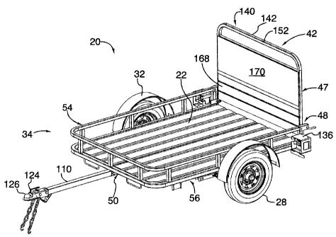
[0029] Referring to FIGS. 1 to 5, there is shown an utility trailer,
designated generally with
reference numeral 20. The trailer 20 is designed to be hitched to the rear of
a motor vehicle (not
shown) and towed. The trailer 20 has a trailer bed 22 which is supported on a
single axle 24 via
a multiple leaf spring-type suspension system 26 (visible in FIG. 5). The
single axle 24 carries a
pair of spaced apart wheels 28 and 30. Each wheel 28, 30 is provided with a
protective wheel
cover 32 that depends from the trailer bed 22. In an alternative embodiment,
the trailer could be
configured as a dual-axle trailer.
[0030] The trailer bed 22 is defined by a support frame 34 and a floor 36
mounted atop the
support frame 34 upon which cargo may be placed. The floor 36 includes two
floor panels 38
and 40 placed side-by-side and secured to the support frame 34. In the
preferred embodiment, the
floor panels 38 and 40 are solid panels of corrugated steel. In other
embodiments, the floor may
be fabricated of expanded steel mesh or any other suitable material.
[0031] A gate 42 is pivotally connected to the support frame 34 at the rear
end 52 thereof. The
gate 42 is movable between a first lowered (out-of-use) storage position 43
(shown in FIG. 11)
and a second declined (in-use) position 44 (shown in Fig. 10). When in the
first lowered storage
position 43, the gate 42 lies flat against the floor 36 trailer bed 22 and
allows cargo (for example,
lumber or the like) loaded onto the trailer bed 22 to extend beyond the
support frame 34. When
in the second declined position 44, the gate 42 forms a ramp 45 which permits
access to the
trailer bed 22 and facilitates loading. The gate 42 may also be moved to a
third raised position
47 (shown in FIG. 2) substantially intermediate the first and second positions
43 and 44. When
the gate 42 is in the raised position 46, the gate 42 is in a substantially
upright position relative to
the floor 36 of the trailer bed 22 and access to the trailer bed 22 is
restricted. As described in
greater detail below, locking means 48 are provided for maintaining the gate
42 in the raised
position 46.
[0032] Referring to FIGS. 5, 6, 7 and 8, the support frame 34 includes: front
and rear ends 50
and 52, a pair of spaced apart, upper and lower, generally U-shaped, bent
structural members or
rails 54 and 56 extending between the front and rear ends 50 and 52; a
plurality of relatively
DM TOR/263490-00001/3474867.1
CA 02693535 2010-02-18
-7-
short, post members or substantially upright struts 58a, 58b, 58c, 58d, 58e,
58f, 58g, 58h, 58i, 58j
and 58k (collectively identified with reference numeral 58) extending between,
and joining the
U-shaped bent members 54 and 56 to each other; and first, second and third
cross-members 60,
62 and 64 connected to the lower, U-shaped bent member 56.
[0033] Both U-shaped member 54, 56 are fabricated from sections of generally
square hollow
structural steel (HSS). In this embodiment, the initial length of member 54
prior to bending is
186 in., whereas the initial length of member 56 prior to bending is slightly
greater, at 186.75 in.
The cross-section of upper U-shaped member 54 is 1.25 in. x 1.25 in. The lower
U-shaped
member 56 has a cross-section measuring 1.5 in. x 1.5 in. The wall thickness
of both members
54 and 56 is 0.065 in.
[0034] In other embodiments, longer or shorter sections could be employed.
Similarly, in
alternate embodiments the cross-section of the upper and lower U-shaped
members could be
increased or decreased to suit a particular application (and support a
particular payload). While
in this embodiment, the U-shaped members have a square cross-section, this
need not be the case
in every application. In an alternate embodiment, U-shaped members having
rectangular cross-
sections could be employed to similar advantage.
[0035] As will be explained in greater detail below, the use of U-shaped
members having flat
faces or sides tends to impart structural strength to the U-shaped members 54
and 56 and tends to
provide suitable connection sites for welding the struts 58 to U-shaped
members 54 and 56,
thereby facilitating manufacture of the utility trailer 20.
[0036] During fabrication, each member 54, 56 is bent inwardly at two
locations to define its
U-shape profile. The bending operation may be carried out by a hydraulic
bender or other
suitable device. Each member 54, 56 includes a back portion 70 and two
opposed, generally
parallel, first and second arm portions 72 and 74, each joined to the back
portion 70. As best
shown in FIG. 7, the back portion 70 is disposed at the front end of the
support frame 34
intermediate the first and second arm portions 72 and 74. Each member 54, 56
is bent to form a
first radiused corner portion 80 whereat the back portion 70 transitions to
become the first arm
portion 72, and a second radiused corner portion 82 whereat the back portion
70 transitions to
DM TOR/263490-00001/3474867.1
CA 02693535 2010-02-18
-8-
become the second arm portion 74. The arm portions 72 and 74 extend generally
perpendicularly
away from the back portion 70 toward the rear end 52 of the support frame 34.
[0037] The formation of radiused corner portions 80 and 82 by bending the
members 54 and
56 obviates the need to have welded connections or joints at the corners of
the support frame 34.
This tends to increase the structural strength of the support frame and its
resistance to twisting,
and further tends to minimize the risks of structural failures at the corners.
In addition, support
frames built in this fashion tend to be easier and cheaper to manufacture than
conventional utility
trailers because of reduced labour required during fabrication.
[0038] Each strut 58 is fabricated from a relatively short section of square
hollow structural
steel. In this embodiment, each strut 58 measures 5.25 in. in length and 1.25
in. x 1.25 in cross-
section. The wall thickness of each strut 58 is 0.065 in. In other embodiment,
the struts could
have a different length or have a rectangular cross-section.
[0039] Each of the struts 58 is welded to the lower face 84 of the upper U-
shaped member 54
and the upper face 86 of the lower U-shaped member 56. Because the edges of
the struts 58 and
each of the upper face 86 and the lower face 84 have planar edges, the welds
between the struts
58 and the U-shaped members tend to be easier to form and tends to be less
prone to failure. It
will thus be appreciated that this arrangement tends to offer real advantages
over the use of
tubular hollow structural steel sections having circular cross-sections, which
require the ends of
the struts to have arcuate notches corresponding to the curvature in the
tubular structural steel
sections making, thereby welding operation more complicated and more prone to
failure.
[0040] Four struts - struts 58a, 58b, 58c and 58d - join the first arm portion
72 of the upper U-
shaped member 54 to the first arm portion 72 of the lower U-shaped member 56.
Strut 58a is
located proximate the terminal or free end 88 of each first arm portion 72,
whereas strut 58d is
disposed at the opposite proximal end 90 of each first arm portion 72 adjacent
the first radiused
corner portion 80. Struts 58b and 58c are positioned intermediate struts 58a
and 58b, with strut
58b being closer to strut 58a than to strut 58d, and strut 58c being closer to
strut 58d than to strut
58a.
DM TOR/263490-00001/3474867.1
CA 02693535 2010-02-18
-9-
[0041] A similar arrangement of struts 58 exists on the opposite side of the
support frame 34.
Struts 58e, 58f, 58g and 58h - join the second arm portions 74 of the U-shaped
members 54 and
56 to each other. The strut 58e is located proximate the terminal or free end
92 of the second arm
portions 74, whereas the strut 58h is disposed near the opposite proximal end
94 of the second
arm portions 74 adjacent the second radiused corner portion 82. Struts 58f and
58g are positioned
intermediate struts 58e and 58h, with strut 58f being closer to strut 58e than
to strut 58h, and
strut 58g being closer to strut 58h than to strut 58e.
[0042] Struts 58i, 58j and 58k connect the back portions 70 of the U-shaped
member 54 and 56
to each other. Strut 58i is disposed near first end 96 of the back portions 70
adjacent the first
radiused corner portion 80 and strut 58k is located near the opposite end 98
thereof adjacent the
second radiused corner portion 82. Strut 58j is positioned roughly midway
between the struts 58i
and 58k.
[0043] While in this embodiment, the support frame 34 includes eleven struts,
in an alternative
embodiment a greater or lesser number of struts laid out in an alternate
arrangement to that
described above, could be employed.
[0044] Referring to FIGS. 6 and 7, the first, second and third cross-members
60, 62 and 64 are
disposed at spaced apart locations between the front and rear ends 50 and 52
of the support frame
34 and extend between and join the arm portions 72 and 74 of the lower U-
shaped member 56.
More specifically, each cross-member 60, 62 and 64 is fixed at one end to the
inner lateral face
100 of arm portion 72 and secured at the opposite end to the inner lateral
face 102 of arm portion
74. The first cross-member 60 is disposed closer to the front end 50 than to
the rear end 52 and
more specifically, between struts 58c and 58d on the one side, and struts 58e
and 58f on the other
side. The second cross-member 62 lies between struts 58b and 58e on the one
side, and struts
58f and 58g on the other side. The third cross-member 64 is located at the
rear end 52 of the
support frame 34 on the same vertical plane as the struts 58a and 58h (as best
shown in FIG. 8).
The cross-members 60, 62 and 64 support the floor panels 38 and 40 that are
mounted between
the first and second arm portions 72 and 74 of the lower U-shaped member 56.
In this
embodiment, the cross-members 60, 62 and 64 are also square hollow structural
steel (HSS)
DM TOR/263490-00001/3474867.1
CA 02693535 2010-02-18
-10-
members measuring 1.25 in x 1.25 in. in cross-section and having a wall
thickness of .065 in.
Each cross-member 60, 62 and 64 is 49.5 in. long.
[00451 As best shown in FIG. 5, a pair of spaced apart, first and second wire
tubes 130 and 132
are mounted to extend beneath and transversely of the first and second cross-
member 60 and 62.
The first wire tube 130 is disposed adjacent and runs generally parallel to
the first arm portion 72
of the lower U-shape member 56. Similarly, the second wire tube 132 lies near
and runs
generally parallel to the second arm portion 74 of the lower U-shape member
56. Each wire tube
130, 132 is intended to receive therethrough the electrical wires running from
a signal light
assembly 134, 136 (as the case may be) carried on either side of the support
frame 34 at the rear
end 52 thereof.
[00461 An elongate tongue 110 centrally disposed between the arm portions 72
and 74 of the
lower U-shaped member 56, projects from the front end 50 of the support frame
34. The tongue
110 is secured to the support frame 34 by a pair of angle ties 112 and 114.
The angle ties 112 and
114 extend between the back portion 70 of the lower U-shaped member 56 and the
first cross-
member 60. Each angle tie 112, 114 has a first leg 116 and a second leg 118
joined to the first
leg 116 and extending perpendicularly thereof. In each case, one end of the
first leg 116 is
welded to the lower face 120 of the back portion 70, while the opposite end is
welded to the
lower face 122 of the first cross-member 60. The tongue 110 is mounted between
the second
legs 118 of angle ties 112 and 114 and retained in place by fasteners 116
inserted through the
aligned apertures defined in the second legs 118 and the tongue 110. The
tongue 110 carries at
its free end 124 a coupler 126 for connecting the trailer 20 to the hitch (not
shown) of a motor
vehicle.
[00471 Referring to FIGS. 2, 9, 10 and 11, the structure and operation of the
gate 42 is now
described in greater detail. The gate 42 includes a frame 140 built up of
several structural
members - more specifically, an inverted U-shaped member 142; a pair of spaced
apart, first and
second cross-members 144 and 146; and a pair of longitudinal ties 148 and 150.
The U-shaped
member 142 is bent inwardly at two locations to define its U-shape profile.
More specifically,
the U-shaped member 142 includes a back portion 152 and two opposed, generally
parallel, first
and second arm portions 154 and 156, each joined to the back portion 152. The
back portion 152
DM TOR/263490-00001/3474867.1
CA 02693535 2010-02-18
-11-
is disposed intermediate the first and second arm portions 154 and 156. The U-
shaped member
142 is bent to form a first radiused corner portion 158 whereat the back
portion 152 transitions to
become the first arm portion 154, and a second radiused corner portion 160
whereat the back
portion 152 transitions to become the second arm portion 156. The arm portions
154 and 156
extend generally perpendicularly away from the back portion 152.
[0048] The first cross-member 144 is carried between the first and second arm
portions 154
and 156 adjacent the first and second radiused corner portions 158 and 160.
One end of the first
cross-member 144 is welded to the inner lateral face 162 of the first arm
portion 154, while the
opposite end is welded to the inner lateral face (not visible) of the second
arm 156. Similarly, the
second cross-member cross 146 extends between the first and second arm
portions 154 and 156,
but is disposed adjacent the terminal or free ends 164 and 166 of the arm
portions 154 and 156.
Joining the first cross-member 144 to the second cross-member 146 are the pair
of spaced apart
longitudinal ties 148 and 150. Longitudinal tie 148 extends generally parallel
to, and is located
proximate the first arm portion 154, while longitudinal tie 150 extends
generally parallel to, and
is located proximate the second arm portion 156.
[0049] The gate 42 further includes first and second, generally rectangular,
back panels 168
and 170 extends which define the support surface for the ramp 45. The first
back panel 168
extends from the terminal ends 164 and 166 toward the back portion 152 (only
part way up the
arm portions 154 and 156) and runs between the first and second arm portions
154 and 156. The
first back panel 168 is secured to each of the second cross-member 146, the
arm portions 154 and
156, and the ties 148 and 150 by welding. The second back panel 170 is mounted
adjacent the
first back panel 168 and extends from the margin of the first back panel 168
to terminate
adjacent the first and second radiused corner portions 158 and 160. Each of
the back panels 168
and 170 is secured to each of the first cross-member 146, the arm portions 154
and 156, and the
ties 148 and 150 by welding. The second back panel 170 is welded to each of
the first cross-
member 144, the arm portions 154 and 156, and the ties 148 and 150. In this
embodiment, each
of the first and second back panels 168 and 170 are solid metal sheets. In
other embodiments,
the back panels could be expanded steel mesh.
DM TOR/263490-00001/3474867.1
CA 02693535 2010-02-18
-12-
[0050] Fixed to the outer lateral faces of each arm portion 154, 156 is a
longitudinal plate 172,
174. The plates 172 and 174 extend beyond the terminal ends 164 and 166 of the
arm portions
154 and 156. Each plate 172, 174 has an aperture (not visible) defined therein
which is adapted
to receive therein a hinge pin 176. The apertures in the plates 172 and 174
are alignable with
corresponding apertures (not visible) defined in plates 178 and 180. The plate
178 extends
transversely of, and is secured to, the strut 58a, while the plate 180 extends
transversely of, and
is fixed to, the strut 58h. The plates 172 and 178 and the hinge pin 176, on
the one side, and the
plates 174 and 180 and the hinge pin 176, on the other side, define the pair
of hinges 184 and 186
which permit the gate 42 to pivot between the lowered position 44 and the
raised position 46. A
short distance away from each plate 172, 174, each arm portion 154, 156 has a
transverse plate
182, 184, respectively, welded to its respective outer lateral face. Each
transverse plate 182, 184
has an aperture (not visible). As explained in greater detail below, the
transverse plates 182 and
184 partially define the locking means 48.
[0051] In the embodiment shown in FIGS. 2 and 9, the locking means 48 includes
a pair of
first and second locking assemblies 190 and 192. The first locking assembly
190 is operable to
act on, or engage, the first arm portion 154. Similarly, the second locking
assembly 192 is
operable to act on, or engage, the second arm portion 156. The locking
assemblies 190 and 192
are identical to each other in all material respects such that the description
of one such locking
assembly - the second locking assembly 192 - will suffice for both. The
locking assembly 192
includes a bracket 194 mounted to the upper U-shaped member 54, the transverse
plate 180 fixed
to the second arm portion 156 of the gate frame 140 (in the case of the first
locking assembly
190, the transverse plate 178 fixed to the first arm portion 154) and a
locking pin 196 engageable
within the bracket 194 and the transverse plate 180 (in the case of the first
locking assembly 190,
the transverse plate 178). The bracket 194 takes the form of a generally C-
shaped channel 198.
The channel 198 is mounted to the second arm portion 74 of the upper U-shaped
frame 54 and
projects beyond the terminal end 92 thereof. The spaced apart legs 200 of the
channel 198 are
oriented downwardly and straddle the second arm portion 74 on either side.
Adjacent its free end
202, the channel 198 has a pair of aligned apertures - each aperture defined
in one leg 200.
These apertures are sized to receive therethrough the locking pin 196.
DM TOR/263490-00001/3474867.1
CA 02693535 2010-02-18
-13-
[0052] In this embodiment, the locking pin 196 has a first relatively,
straight portion 210 and a
second dog-legged portion 212 joined to the first portion 210. The first
straight portion 210 is
adapted for insertion in the aligned apertures 204 defined in the legs 200 of
the channel 198. The
second dog-legged portion 212 defines a handle with which to grasp the locking
pin 196.
[0053] To maintain the gate 42 in the raised position 46, the gate 42 is
pivoted such that it
stands upright of the trailer bed 22. Care is taken to align, on the one side,
the aperture defined
in the plate 180 with the apertures formed in the bracket 194 mounted to the
second arm portion
74, and on other side, the aperture defined in the plate 178 with the
apertures formed in the
bracket 194 mounted to the first arm portion 72. Thereafter, the straight
portion 210 of the
locking pin 196 is inserted through the aligned apertures in the plate 180 and
bracket 194, and in
the plate 178 and opposite bracket 194. When the locking pins 196 are fully
inserted, the
terminal ends 214 of the straight portions 210 project beyond the plates 180
and 178. In order to
move the gate 42 to the first lowered (out-of-use) storage position 43 or to
the second declined
(in-use) position 44, the locking pin 196 is disengaged from the plates 182
and 184 and the
brackets 194 and the gate 42 is pivoted to the desired position.
[0054] From the foregoing, it will be appreciated that it is advantageous for
a utility trailer to
be provided with a support frame employing a dual, superimposed, bent U-shaped
configuration
with planar faces. Such a configuration tends to enhance the structural
strength of the utility
trailer and tends to offer improved resistance against bending or twisting.
With the absence of
welded connections at the corners, the support frame constructed in accordance
with the
principle of the present invention tend to be less prone to failure and more
robust. As regards
manufacturing, configured in this manner, the support frame (and the utility
trailer) tend to
require less welding. This tends, in turn, tends to lead to efficiencies in
manufacturing resulting
in reduced labour and costs.
[0055] Although the foregoing description and accompanying drawings relate to
specific
preferred embodiments of the present invention as presently contemplated by
the inventor, it will
be understood that various changes, modifications and adaptations, may be made
without
departing from the spirit of the invention.
DM TOR/263490-00001/3474867.1