Note: Descriptions are shown in the official language in which they were submitted.
CA 02693555 2010-01-14
WO 2009/012380 PCT/US2008/070318
1
SYSTEM AND METHOD FOR ANALYZING
ROLLING STOCK WHEELS
[0001] This application claims priority to U.S. Provisional Application
60/950,216 filed July 17, 2007, which is incorporated herein by reference in
its entirety.
BACKGROUND
1. Field
[0002] The present invention relates to a system and method for analyzing
rolling stock wheels. The present invention more specifically relates to a
system and
method involving multiple cameras and lighting for measuring the profiles of
such
wheels.
2. Related Art
[0003] The rolling stock of a railroad, such as box cars, flat cars, tanker
cars,
hopper cars, gondolas, piggy back carriers for semi-tractor trailers and/or
containers,
passenger cars, and the like, are subject to wear, fatigue and the like. This
is especially
true of the wheels and trucks of such rolling stock. Accordingly, it is
typically necessary
or desirable to inspect such rolling stock, and especially the trucks and
wheels of such
rolling stock, on occasion to insure that the rolling stock remains safe to
use and is not
likely to experience a breakdown in the interval between the current
inspection and the
next inspection of that piece of rolling stock.
[0004] Traditionally, such inspections were performed manually. Not only
was such manual inspection time consuming and expensive, it was difficult to
insure
that a given piece of rolling stock was inspected on any reasonable schedule,
[0005] Accordingly, as set forth in U.S. Patents 6,911,914; 6,909,514;
6,872,945; 6,823,242; 6,768,551; 5,793,492; 5,677,533; 5,596,203; 5,448,072;
5,247,338; 3,253,140; and 3,206,596, each of which is incorporated herein by
reference
for its teachings, over the last thirty years, various systems and methods
have been
developed for automatically inspecting various aspects and parameters of
railway rolling
stock, such as railroad wheel and bearing temperatures, hot rail car surfaces,
wheel
profiles, and the like. Conventionally, such systems and methods have used
passive
sensors that generate a 1-dimensional, time-varying signal as the piece of
rolling stock
passes by the sensor. To provide additional dimensional inforination, multiple
sensors
CA 02693555 2010-01-14
WO 2009/012380 PCT/US2008/070318
2
can be aiTanged either along or peipendicular to the railway rail. More
recently, optical-
based systelns that generate 2-dimensional images of various components of
railway
rolling stock, such as wheels, truck assemblies, car bodies of the rolling
stock and the
like, have been used to inspect such rolling stock.
[0006] Some optical-based systems provide for laser-based rolling stock
wheel profile measuring systems. Such systems (often installed way side)
typically
derive wheel profile measurements by projecting laser lines onto a surface of
the wheel
and then capturing an image of the wheel surface with the laser line projected
onto it.
However, such known systems do not realize certain advantageous features
(and/or
combinations of features).
[0007] For example, the accuracy of measurements obtained using such laser
systems is highly dependent on the calibration of the systems. Even minor
changes in
the setup and/or calibration may not be detectable immediately, therefore
increasing the
risk of unreliable data. Visual review or other manual processing of an object
captured
in the image is difficult because any image obtained using such systems is
directed
primarily to a projected laser line on the object, rather than an image of the
object itself.
As a result, any such processing is difficult, unreliable and has reduced
value. For
example, known systems typically derive certain wheel parameters (such as
wheel
hollowing) by assumption because the wheel parameter may not be clearly seen
in
images captured by such systems.
[0008] Such known systems often require correct calibration of the object to
be measured. If the actual object being measured differs from the object that
was
calibrated, then errors are likely. Further, rolling stock wheels typically
vary in size.
Such variation typically requires interpolation and/or extrapolation, which
may
introduce errors.
[0009] The apparatus of such systems is typically subjected to vibration from
passing rolling stock. Large vibrations may result in movement including
relative
movement between the laser line and the optical center of the image capturing
apparatus. Such vibration and movements can lead to or result in errors.
[0010] Further, the laser line(s) of such known systems intended to overlay
parent material of the rolling stock wheel may instead overlay foreign
materials that are
not part of the wheel (e.g. grease on the flanges from lubricators, etc.).
Because typical
processing algorithms assume that the laser line overlays only the parent
material of the
CA 02693555 2010-01-14
WO 2009/012380 PCT/US2008/070318
3
wheel, foreign material may negatively affect the accuracy and reliability of
any
measurements obtained from such systems.
[0011] The lasers of such known systems also present a potential safety
hazard. While such systems typically include protective measures in the event
of a
system failure, such protective measures cannot eliminate the risk of laser
exposure.
[0012] It would be desirable to provide a system, method or the like for
capturing, measuring a.nd/or analyzing rolling stock wheel parameters of the
type
disclosed in the present application that includes any one or more of these or
other
advantageous features: a system and/or method that does not substantially
depend upon
detailed calibration of the system or of the object to be measured; a system
and/or
method that is affected little by foreign materials that are not part of the
original rolling
stock wheel; a system and/or method that does not utilize lasers and thereby
eliminates
the risks of exposure to such lasers; and a system and/or method that does not
need to
derive wheel parameters by assumption but instead may accurately measure
complete
wheel parameters including wheel hollowing.
[0013] Such systems and methods for capturing, measuring and/or analyzing
rolling stock wheel parameters would be advantageous for a number of reasons.
These reasons include allowing the systems, or inspection stations that
utilize such
systems, to be located at points where most rolling stock is likely to be
inspected at
reasonable intervals, such as the entrances or exits to rail yards, without
having to
significantly involve railroad personnel in the actual inspection.
Furthermore, such
systems and methods are designed to inspect the rolling stock at speed. That
is, the
inspection can occur while the rolling stock moves at its normal rate of
travel past the
inspection station. In contrast, manual inspections typically require the
rolling stock
to be stopped to allow the railway personnel access to the various components
to
make the measurements. By allowing the rolling stock to move at speed through
the
inspection station, the inspection can occur without substantially negatively
affecting
the schedule of a particular train, thus reducing the cost of the inspection
and delays in
transporting goods.
[0014] Additionally, such systems and methods would avoid several
limitations and/or disadvantages of laser-based systems and/or are inherently
safer
than laser-based systems.
CA 02693555 2010-01-14
WO 2009/012380 PCT/US2008/070318
4
SUMMARY
[0015] The present invention relates to a system for capturing, measuring
and/or analyzing rolling stock wheel parameters comprising a first flange
camera
provided adjacent a track side of a first rail, wherein the first flange
camera is
positioned to capture an image of at least a portion of a first wheel above
the first rail;
a first inside rim camera provided adjacent a track side of a second rail,
wherein the
first inside rim camera is positioned to capture an image of at least a
portion of the
first wheel; a first outside rim camera provided adjacent a field side of the
first rail,
wherein the first outside rim camera is positioned to capture an image of at
least a
portion of the first wheel including at least a portion of an internal
diameter of the first
wheel; at least one strobe light positioned to help illuminate at least a
portion of the
first wheel; and at least one backface illumination plate provided adjacent
the track
side of the first rail and positioned to reflect light toward the first wheel.
[0016] The present invention relates to a method of capturing, measuring
and analyzing rolling stock wheel parameters, comprising reflecting light
toward a
first wheel with a backface illumination plate provided adjacent a track side
of a first
rail; capturing an image of at least a portion of the first wheel above the
first rail with
a first flange camera provided adjacent the track side of the first rail;
capturing an
image of at least a portion of the first wheel above the first rail with a
first inside rim
camera provided adjacent a track side of a second rail; and capturing an image
of at
least a portion of the first wheel above the first rail, including at least a
portion of an
internal diameter of the first wheel, with a first outside rim camera provided
adjacent a
field side of the first rail.
[0017] The present invention relates to a method of providing a system for
capturing, measuring and analyzing rolling stock wheel parameters, comprising
positioning and orienting a first flange camera adjacent a track side of a
first rail to
capture an image of at least a portion of a first wheel above the first rail;
positioning
and orienting a first inside rim camera adjacent a track side of a second rail
to capture
an image of at least a portion of the first wheel above the first rail;
positioning and
orienting a first outside rim camera adjacent a field side of the first rail
to capture an
image of at least a portion of the first wheel above the first rail;
positioning and
orienting at least one strobe light, such that the at least one strobe light
helps
illuminate at least a portion of the first wheel; and positioning and
orienting at least
CA 02693555 2010-01-14
WO 2009/012380 PCT/US2008/070318
one backface illuminate plate adjacent the track side of the first rail to
reflect light
toward the first wheel.
[0018] These and other features and advantages of various exemplary
einbodiinents of systems and methods according to these inventions are
described in,
or are apparent from, the following detailed descriptions of various exemplary
embodiments of various devices, structures and/or methods according to this
invention.
BRIEF DESCRIPTION OF DRAWINGS
[0019] Various exemplary embodiments of the systems and methods
according to this invention will be described in detail, with reference to the
following
figures, wherein:
[0020] Fig. 1 is a sectional view of a portion of a wheel head on a rail.
[0021] Fig. 2 is a partial sectional view of a wheel profile of a rolling
stock
wheel positioned on a rail.
[0022] Fig. 3 is a top view of an exemplary embodiment of a systein for
capturing, measuring and/or analyzing rolling stock wheel parameters.
[0023] Fig. 4 illustrates an image that may be produced by a flange cainera
of an exemplary embodiment of a system for capturing, measuring and/or
analyzing
rolling stock wheel parameters.
[0024] Fig. 5 illustrates an image that may be produced by an inside rim
camera of one exemplaiy embodiment of a system for capturing, measuring and/or
analyzing rolling stock wheel paraineters.
[0025] Fig. 6 illustrates an image that may be produced by an outside rim
camera of an exemplary embodiment of a system for capturing, measuring and/or
analyzing rolling stock wheel paralneters. [0026] Fig. 7 is a partial
sectional view of a backface illumination meinber
and markers positioned about a rail and a wheel head.
[0027] Fig. 8 is a photograph produced by a flange camera of an exemplary
embodiment of a system for capturing, measuring and/or analyzing rolling stock
wheel parameters.
CA 02693555 2010-01-14
WO 2009/012380 PCT/US2008/070318
6
[0028] Fig. 9 is a photograph produced by a flange camera of an exemplary
embodiment of a system for capturing, measuring and/or analyzing rolling stock
wheel parameters, which system includes a backface illumination member.
[0029] It should be understood that the drawings are not necessarily to scale.
In certain instances, details that are not necessary for an understanding of
the
invention or render other details difficult to perceive may have been omitted.
It
should be understood, of course, the invention is not necessarily limited to
the
particular embodiments illustrated herein.
DETAILED DESCRIPTION
[0030] A railroad can own tens of thousands, if not more, of pieces of rolling
stock. Such rolling stock includes both locomotives and freight and/or
passenger cars.
Typically, a railroad owns dozens of different types of freight cars, such as
box cars,
tanker cars, gondolas, hoppers, flat cars, piggy-back flat cars, container
carriers,
livestock cars and the like. If a railway provides passenger service, the
rolling stock
can contain passenger cars, baggage cars, mail cars, sleeper cars, dining
cars,
observation cars and the like. Inspecting rolling stock is typically
problematic (e.g.
due to its mobile nature). Accordingly, as outlined in the above-incorporated
U.S.
Patents, automatically inspecting rolling stock as it passes by an inspection
station can
be more efficient than manually inspecting the rolling stock.
[0031] As outlined above, while manually inspecting the rolling stock can
provide very precise and accurate measurement of various parameters associated
with
the rolling stock, such manual measurements are time consuming and expensive.
Not
only does manual inspection require trained personnel, manual inspection
Tequires
stopping a train containing the rolling stock for a period of time. Because
railways
earn profits by moving goods from one place to another, delays for inspecting
the
rolling stock can negatively impact the railway (e.g. directly reduce the
profits earned
by the railway).
[0032] In various embodiments, systems including machine vision absent
any laser lines are utilized due to known disadvantages of laser line
technology and
systems. Laser-based systems unnecessarily complicate wheel profile
measurements
and increase the risk of erroneous measurements. Further, the laser-included
systems
CA 02693555 2010-01-14
WO 2009/012380 PCT/US2008/070318
7
also present a potential safety hazard (risk of laser exposure in the case any
protective
system fails).
[0033] In various embodiments, the system related to the present invention
utilizes strobe lighting and high-speed cameras (without lasers) to capture
paraineters
of rolling stock wheels. In various embodiments, the system provides accurate
measurements of the complete profile and wheel head of the wheel, including
wheel
hollowing measurements. The system does not require assumptions to derive
wheel
parameters, but uses parameters captured from images, thereby improving the
maintenance practices of the railroads by providing railroad operators with a
reliable
and easy-to-maintain wheel profile and wheel parameter measuring system, and
increasing the safety of railroad operations. In addition, the system is
capable of
measuring all wheels of a various rolling stock traveling at normal speeds,
e.g. at least
60 miles per hour.
[0034] Fig. 1 illustrates a sectional view of a rolling stock wheel head 100
atop a rail 110. Wheel head 100 typically includes a rim 120 and a flange 130.
Wheel
head 100 also typically includes a running surface 140, which generally
includes a
portion of rim 120 in contact with rail 110. Because wheels are known to move
relative to a rail, running surface 140 of a wheel may be wider than a rail
and may
change over time and/or during the use.
[0035] Fig. 2 illustrates a wheel profile 150 of a rolling stock wheel above a
rail. If a wheel profile 150 is accurately known or measurable, a variety of
wheel
parameters such as thickness of the rim, height and width of flange 130, and
wheel
hollowing may be determined. Wheel hollowing is generally considered a
reduction
in the thickness of the rim substantially near running surface 140 of the
wheel head.
Wheel profile 150 illustrated in Fig. 2 exhibits wheel hollowing.
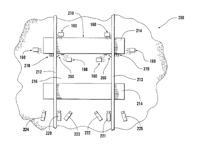
[0036] Fig. 3 shows an exemplary embodiment of an inspection station 200,
as a system for capturing, measuring and/or analyzing rolling stock wheel
parameters,
according to this invention. As shown in Fig. 3, in one exemplary embodiment,
inspection station 200 comprises a section 210 of track where a variety of
image
capture devices, including a first flange camera 220, a second flange camera
221, a
first inside rim camera 222, a second inside rim camera 223, a first outside
rim camera
224 and a second outside rim camera 225, are located. In various exemplary
embodiments, inspection station 200 also includes strobe lighting 160 and one
or
CA 02693555 2010-01-14
WO 2009/012380 PCT/US2008/070318
8
more triggering systems in communication with one or more cameras and/or
strobe
lighting 160. The system may also include one or more data processing units
and/or
one or more communication links in communication with at least one of the
cameras.
[0037] As also shown in Fig. 3, in one embodiment, section 210 of track
includes portions of a first rail 212 and a second rail 213 that are provided
on one or
more sleepers 214. Sleepers 214 may be embedded in a mass of ballast 216.
Rails
212, 213 may be connected to sleepers 214 using any known or later-developed
technique and/or device. As shown in Fig. 3, image capture devices may be
located
outside one or both of rails 212, 213 (i.e., located to a field side of one or
both rails
212, 213) and/or between rails 212, 213 (i.e., located on a track side of
rails 212, 213).
[0038] In various exemplary embodiments, the various image capturing
devices, such as cameras 220-225 shown in Fig. 3, utilized in the system are
positioned and/or angled to capture at least portions of wheel heads of wheels
of one
or more wheel sets. In various exemplary embodiments, the various image
capturing
devices utilized in the system may also be positioned and/or located to help
magnify
one or more captured objects.
[0039] More specifically, in various exemplary embodiments, first flange
camera 220 and second flange camera 221 are provided (e.g. located and
positioned)
adjacent the track side of a first rail 212 and a second rail 213,
respectively, and
pointed substantially at a flange of a first wheel and a flange of a second
wheel of a
wheel set, respectively, and located and positioned so that the wheel set may
pass
without contacting either camera 220, 221.
[0040] Likewise, in various exemplary embodiments, first inside rim camera
222 is provided between first rail 212 and second rai1213 (e.g. adjacent the
track side
of second rail 213) and oriented (e.g. at a slightly vertical angle and
horizontal angle)
to allow first inside rim camera 222 to capture an image of at least a portion
of a rim
of the first wheel, while second inside rim camera 223 is provided between
first rail
212 and second rai1213 (e.g. adjacent the track side of first rai1212) and
oriented (e.g.
at a slightly vertical angle and horizontal angle) to allow second inside rim
camera
223 to capture an image of at least a portion of a rim of the second wheel.
[0041] Meanwhile, in various exemplary embodiments, first outside rim
camera 224 and second outside rim camera 225 are provided to the field side of
first
rail 212 and second rail 213, respectively, and oriented (e.g. at a slightly
vertical angle
CA 02693555 2010-01-14
WO 2009/012380 PCT/US2008/070318
9
and horizontal angle) to allow first outside rim camera 224 and second outside
rim
camera 225 to capture an image of at least a portion of the rim of a first
wheel and at
least a portion of the rim of a second wheel, respectively.
[0042] It should be appreciated that the image capturing devices may be
positioned, oriented and aligned any nuinber of ways. In various exemplary
embodiments, however, the image capturing devices are positioned, aligned and
oriented to help allow the image capturing devices to capture precisely an
area of
interest, e.g. the majority of a wheel's profile.
[0043] It should also be appreciated that the various image capturing
devices, such as cameras 220-225, can be implemented by incorporating one or
more
physically distinct imaging systems, such as complete digital cameras, into an
image
capture device body. In one embodiment, the various image capturing devices
can be
implemented as a plurality of physically independent image capture systems,
such as
complete digital caineras. In one embodiment, the various image capturing
devices
can implement one or more imaging systems using physically distinct lens
assemblies
and image capture electronics, with common data storage, input/output control
and
other electronics. It should be appreciated that any known or later-developed
type or
types of image capture systems may be used to implement any one of or multiple
ones
of the various image capturing devices, including cameras 220-225.
[0044] Figs. 4 - 6 illustrate various images that may be captured by three
cameras of the system intended to capture images of one or more wheels
positioned
substantially above, for example, a second rail (e.g., the second flange
camera, the
second inside rim camera and the second outside rim camera). For example, as
shown
in Figs. 4-6, the majority of a profile of a wheel 250 may be viewable and/or
measurable utilizing images produced by the second flange camera, the second
inside
rim camera, and the second outside rim camera. More specifically, as depicted
in Fig.
6, at least a portion of an internal diameter of whee1250 should be visible
from the
location of an outside rim cainera, e.g., the second outside rim camera.
[0045] Because wheel 250 is positioned on second rail 213, the second
flange camera, second inside rim camera and second outside rim camera may not
capture in any of the images the complete running surface of wheel 250.
However,
any portion of the running surface of whee1250 that is not captured in the
images
should be in contact substantially with second rail 213. More particularly,
the portion
CA 02693555 2010-01-14
WO 2009/012380 PCT/US2008/070318
of the i-unning surface of wheel 250 should be in contact with the profile of
second rail
213. The profile of second rail 213 may be measured accurately before and
after
installation of the system and re-measured at regular intervals. For example,
a rail
typically wears slowly and an annual measurement of the profile of the rail is
generally considered sufficient, even under very heavy traffic conditions and
use.
Because the profile of second rail 213 is known or at least measurable, by
coinbining
the profile of second rail 213 with data from images captured by second flange
camera
221, second inside rim camera 223, and second outside rim camera 225, a
complete or
substantially complete "image" of the running surface of whee1250 may be
constructed or determined.
[0046] Complete "images" of the running surfaces of other wheels traveling
either rail may be similarly determined. In various embodiments, the running
surface
of a wheel head above the first rail may be determined using the rail profile
of the first
rail and images captured by the first flange camera, first inside rim camera
and first
outside rim camera.
[0047] Further, from the images and the known rail profile, accurate
measurements of wheel parameters including wheel hollowing may be made.
Furthermore, a wheel profile may be accurately determined because
substantially all
of the wheel head is visible on the collective images. All necessary
references of the
wheel head are visible and, using automated algorithms for image processing,
the
wheel profile and wheel head may be determined and all wheel profile
parameters
measured accurately, including wheel hollowing. Once the processing algorithms
have determined parameters of the wheel head, the final processing algoritluns
will
include the portion of the wheel that is in contact with the rail, and thus
allow
determination of the wheel profile and the entire wheel head.
[0048] As shown in Figs. 3-9, the system may also include one or more
markers 260 provided about the first and/or second rails, such as those
markers
disclosed in PCT Patent Application Serial No. PCT/US07/63499, which
application
is incorporated herein by reference in its entirety. Because such markers 260
may be
included in one or more images captured by the systein, the correct
interrelationships
of the images may be more easily determined and, as a result, accurate
measurements
of the wheel parameters and the wheel profile may be obtained.
CA 02693555 2010-01-14
WO 2009/012380 PCT/US2008/070318
11
[0049] More specifically, markers 260 may be located in areas to be
captured in the images to enable referencing to the top of the rail or to each
of the
images. This may ensure more accurate measurements of the wheel parameters
(including wheel hollowing) and the wheel profile.
[0050] As shown in Figs. 3 and 6, the system of the present invention may
also include one or more sensors 270 such as those disclosed in U.S. Patent
7,278,305
Application Serial No. 60/588,910, which is incorporated herein by reference
in its
entirety. Such sensors 270 may be used to determine the existence of any speed
variations of each wheel set on a train. In addition, such sensors 270 may be
used to
improve the timing of the cameras and help ensure that all images are timely
captured.
Further, where the distances from the cameras to the captured objects are
known, all
measurements may be corrected for any angle of attack or tracking of the
captured
objects.
[0051] As shown in Figs. 7and 9, the system may also include one or more
backface illumination plates 280 provided between first rail 212 and second
rail 213
(e.g. adjacent the track side of first rail 212 and/or second rai1213) and
oriented to
reflect light toward the flange and/or rim of one or more wheels traveling
along first
rail 212 and/or second rai1213. For example, backface illumination plate 280
may be
mounted vertically and oriented toward the camera 10 to 15 degrees relative to
the
general longitudinal direction of the rail. In various embodiments, backface
illumination plate 280 is provided to avoid contact with any of the wheels.
Further, in
various embodiments, backface illumination plate 280 may be flexibly mounted
(e.g.
spring-mounted) so that if it is contacted by the wheel or any components or
equipment of rolling stock, it may flex and/or give way and substantially
retuni to its
original and/or optimal position. Each backface illumination plate 280 may be
constructed of any type of material. In various einbodiments, backface
illumination
plate 280 will be constructed of at least a surface material having reflective
characteristics.
[0052] Fig. 8 is a photograph of first rai1212, a wheel and markers 260
utilizing an exemplary embodiment of a system not including a backface
illumination
plate. Fig. 9 is a photograph of first rail 212, a wheel and markers 260
captured by an
exemplary embodiment of a system including backface illumination plate 280. As
shown by Figs. 8 and 9, in various exemplary embodiments, backface
illumination
CA 02693555 2010-01-14
WO 2009/012380 PCT/US2008/070318
12
plate 280 helps illuminate at least a portion of a backface of the wheel
captured in an
image to enhance the quality and clarity of the captured image. In various
embodiments, the utilization of backface illumination plate 280 may also help
illuminate any markers utilized.
[0053] It is important to note that the construction and arrangelnent of the
elements of the system as shown and described in the preferred and other
exemplary
embodiments is illustrative only. Although only a few embodiments of the
present
inventions have been described in detail in this disclosure, those skilled in
the art who
review this disclosure will readily appreciate that many modifications are
possible
(e.g., variations in sizes, dimensions, structures, shapes and proportions of
the various
elements, values of parameters, mounting arrangements, use of materials,
colors,
orientations, etc.) without materially departing from the novel teachings and
advantages of the subject matter recited. For example, elements shown as
integrally
formed may be constructed of multiple parts or elements and/or elements shown
as
multiple parts may be integrally formed, the operation of interfaces may be
reversed or
otherwise varied, the length and/or width of the structures and/or members or
connections or other elements of the system may be varied, the nature or
number of
adjustment positions provided between the elements may be varied, the position
of
elements may be reversed or otherwise varied, and the nature or number of
discrete
elements or positions may be altered or varied. It should be noted that the
elements
and/or assemblies of the system may be constructed from any of a wide variety
of
materials that provide sufficient strength or durability, in any of a wide
variety of
colors, textures and combinations. Accordingly, all such modifications are
intended
to be included within the scope of the present invention. Other substitutions,
modifications, changes and omissions may be made in the design, operating
conditions and arrangement of the preferred and other exemplary embodiments
without departing from the scope of the present inventions.