Note: Descriptions are shown in the official language in which they were submitted.
CA 02693653 2015-09-25
1
Soil working device
The invention relates to a mobile soil working device for forming cavities in
the soil.
A known soil working device comprises a machine frame and a drive for at
least one piercing tool that can be lifted and lowered, said piercing tool be-
ing operable to be pierced into the soil and thereafter to be withdrawn. A
guiding element, e.g. a support arm, for at least one piercing tool is movea-
bly guided on the machine frame. Prior to piercing, the piercing tool is ar-
ranged in a starting position under a predetermined piercing angle. A tool
holder holds one or a plurality of piercing tools. The tool holder is
supported
around a first pivot axis in said guiding element which can be lifted and
lowered by the drive, so that during engagement with the soil, i.e. under
application of force, the piercing tool can be pivoted relative to the guiding
element. Upon release of the applied force, a device exerts a restoring mo-
ment on the tool holder that acts around the first pivot axis, so that the
piercing tool after withdrawal from the soil will pivot back again into the
starting position.
Devices of the above type serve for forming cavities in the soil with the aid
of piercing tools, wherein slit-shaped cavities will be generated in the depth
regions of the soil and holes of the smallest possible size will remain on the
surface. Said cavities allow for an improved drainage of water and enhance
the aeration of the soil, and the loosening of the soil is effective to
improve
the growth of plants, especially of grasses.
From European Laid-open EP-A-0037595, there is known a soil working de-
vice comprising two support arms, guided in the manner of a parallelogram,
which on one end pivotably carry a tool holder and on the other end are
CA 02693653 2015-09-25
2
pivotably supported on the machine frame. The pushing rod of the crank
drive is articulated to the tool holder and will drive the same, thus causing
it
to perform an upward and downward movement. One of the two support
arms is adjustable in length and includes a restoring spring with a stopper.
As long as the piercing tool is outside the soil, the support arm is in abut-
ment on the stopper due the spring force. In the situation where the pierc-
ing tool is in the pierced state and the soil working device is being moved
on, the piercing tool together with the tool holder will be pivoted opposite
to
the travel direction, and the length-adjustable support arm will be extended
against the spring force.
In the soil working devices known as of yet, spring elements are used which
exert a restoring moment on the piercing tools so that the piercing tools,
once they are outside the soil, will move back into their starting position
again. Hereunder, the starting position is to be understood as that position
which said at least one piercing tool assumes briefly prior to piercing. Out-
side the soil, however, under the effect of the mass inertia and of the up-
ward and downward movement, the moment of inertia of the tool holder
and the piercing tool will act against the restoring moment of the spring. For
this reason, use is made of spring elements of high spring stiffness in order
to move the piercing tools back into their starting position again. The spring
elements with high spring stiffness, however, cause an increased risk that
the piercing tools, while still within the soil, will cut slits into the soil
surface
instead of generating the desired small holes.
In view of the above, it is an object of the invention to provide a device of
the initially described type wherein the risk of slit formation is reduced.
The invention advantageously provides that the overall center of gravity of
the tool holder and the at least one piercing tool is arranged in relation to
the first pivot axis to the effect that the moment of inertia of the tool
holder
CA 02693653 2010-01-11
3
and the piercing tool, counteracting the restoring moment, is at least par-
tially reduced or compensated or overcompensated.
The overall center of gravity of the tool holder and the at least one piercing
tool can be arranged in relation to the first pivot axis in such a manner that
the moment of inertia of the tool holder and the piercing tool, counteracting
the restoring moment, is overcompensated to the effect that the moment of
inertia acting around the first pivot axis will form at least a part of the re-
storing moment.
This embodiment has the advantage that the use of a spring element with
lesser spring stiffness is rendered possible or that even no spring element at
all is required because the moment of inertia of the tool holder and the
piercing tool, counteracting the restoring moment, is at least partially re-
duced or compensated or overcompensated to the effect that the moment
of inertia acting around the first pivot axis will form at least a part of the
restoring moment.
A further advantage resides in a reduction of the number of component
parts, whereby the production costs are considerably reduced. In addition,
the operating life can be increased and the maintenance work can be re-
duced.
It is a further advantage that, if stoppers are provided for limiting the re-
storing movement back into the starting position, the impact load acting on
the machine frame, on the machine elements and especially on the bearing
can be reduced.
The overall center of gravity of the tool holder and the at least one piercing
tool can be situated on the first pivot axis.
CA 02693653 2010-01-11
4
According to a further exemplary embodiment of the invention, it is pro-
vided that an additional mass is coupled to the tool holder and is preferably
fastened thereto for common rotation therewith.
The overall center of gravity of said additional mass, the tool holder and the
at least one piercing tool is arranged in relation to the first pivot axis to
the
effect that the moment of inertia of the tool holder, said additional mass
and the at least one piercing tool, counteracting the restoring moment, is at
least partially reduced or compensated or overcompensated.
The overall center of gravity of said additional mass, the tool holder and the
at least one piercing tool can be arranged in relation to the first pivot axis
in
such a manner that the moment of inertia of the tool holder, said additional
mass and the at least one piercing tool, counteracting the restoring mo-
ment, is overcompensated to the effect that the moment of inertia acting
around the first pivot axis will form at least a part of the restoring moment.
The overall center of gravity of said additional mass, the tool holder and the
at least one piercing tool can be situated on the first pivot axis.
According to a further exemplary embodiment, it is provided that the dis-
tance, preferably the horizontal distance, of the overall center of gravity of
the tool holder and the at least one piercing tool, or the distance,
preferably
the horizontal distance, of the overall center of gravity of said additional
mass, the tool holder and the at least one piercing tool from the first pivot
axis is adjustable, preferably centrally so for all tool holders.
This has the advantage that, thereby, the amount of the moment of inertia
of the tool holder and the at least one piercing tool, or of said additional
mass, the tool holder and the at least one piercing tool, will be adjustable.
The guiding element can be a support arm pivotably supported in a second
pivot bearing on the machine frame.
CA 02693653 2010-01-11
Said support arm can be configured for length adjustment against a spring
force. This has the advantage of achieving an additional reduction of the
danger of slit formation.
At least one helically or spirally shaped, metallic torsion or pressure spring
can generate the spring force counteracting the extending of the support
arm. Said spring preferably has a degressive spring characteristic.
At least one torsion and respectively pressure spring element or a spring
damper element can be arranged to the side of the support arm, preferably
parallel to the support arm. Said spring element allows for a pivoting
movement of the tool holder around the first pivot axis and, upon release of
the engagement with the soil, it will exert at least a part of the restoring
moment on the tool holder so that the piercing tool after withdrawal from
the soil will be pivoted back into the starting position again.
According to a further exemplary embodiment, it can be provided that said
torsion and respectively pressure spring element or said spring damper
element is arranged on the machine frame in a manner causing it to exert a
high restoring moment on the tool holder if the piercing tool is located out-
side the soil, and causing it to exert a small restoring moment on the tool
holder if the piercing tool is located in the soil.
According to a further exemplary embodiment of the invention, it is pro-
vided that, between the tool holder and the guiding element, a torsion ele-
ment is arranged which allows for pivoting movement of the tool holder rel-
ative to the guiding element and, upon release of the influence of the force,
exerts at least a part of the restoring moment on the tool holder, so that
the piercing tool after withdrawal from the soil will be pivoted back into the
starting position again.
CA 02693653 2010-01-11
6
Said torsion element can consist of at least one elastomeric element, an
elastomeric compound element or a helically or spirally shaped, metallic
torsion spring.
According to a further exemplary embodiment of the invention, it is pro-
vided that the torsion element comprises at least two magnetic elements,
said at least two magnetic elements being oriented relative to each other in
a manner causing them to allow for pivoting movement of the tool holder
around the first pivot axis and, upon release of the engagement with the
soil, to exert at least a part of the restoring moment on the tool holder, so
that the piercing tool after withdrawal from the soil will be pivoted back
into
the starting position again.
Said magnetic elements can consist of permanent magnets or solenoids, the
solenoids being adapted to be activated or deactivated in dependence on
the movement phase.
Exemplary embodiments of the inventions will be explained in greater detail
hereunder with reference to the drawings.
In the drawings, the following is schematically shown:
Fig. 1 is a lateral view of a soil working device,
Fig. 2 is a lateral view of an exemplary embodiment of the invention with
piercing tool,
Fig. 3 is a representation of acceleration and speed developments of two
points of the support arm,
Fig. 4 is a lateral view of an exemplary embodiment of the invention with
central positioning device,
CA 02693653 2010-01-11
7
Fig. 5 is a lateral view of a further exemplary embodiment wherein a heli-
cally or spirally shaped torsion spring is used,
Fig. 6 is a lateral view of a further exemplary embodiment wherein an
elastomer-metal compound element is used,
Fig. 7 is a lateral view of a further exemplary embodiment wherein the
torsion element comprises three magnets,
Fig. 8 is a lateral view of a further exemplary embodiment of the invention
with spring damper element,
Fig. 9 shows a further embodiment with length-adjustable support arm.
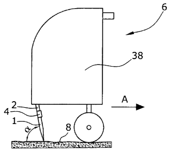
Shown in Fig. 1 is a lateral view of a mobile soil working device which is
self-propelled or can be drawn with the aid of a tractor. Said soil working
device 6 comprises a machine frame 38 whereon, via guiding elements 30,
a plurality of piercing tools 1 adapted to be lifted and lowered by a drive
36,
are pivotably supported. Due to said lifting and lowering movement, the
piercing tools 1 are alternately pressed into the soil 8 and, under the effect
of the forward travel of the soil working device 6, perform a tilting move-
ment in the soil 8. Thereby, the soil 8 will be broken up below the piercing
hole, whereby e.g. the drainage of the soil 8 is improved. In spite of the
travel speed of the soil working device 6, the piercing hole in the surface of
the soil shall remain as small as possible.
Preferably, said at least one piercing tool 1 is fastened in a tool holder 2
with the aid of a holding means 4. Said tool holder 2, being guided by a
guiding element 30, is suited for attachment of piercing tools 1 of various
lengths and shapes as well as various diameters. Said guiding element 30 is
arranged to perform a lifting and lowering movement while driven prefera-
bly by a crank drive 36. By way of alternative, guiding element 30 can also
be driven hydraulically or electrically.
CA 02693653 2010-01-11
8
Tool holder 2 is supported on guiding element 30 for pivoting around a first
pivot axis 12, with tool holder 2 holding therein a piercing tool 1 or a group
of piercing tools 1 which under the effect of said lifting and lowering move-
ment can be pierced into the soil 8 and be withdrawn again. It is possible to
drive a plurality of preferably mutually adjacent piercing tools 1 or mutually
adjacent groups of piercing tools 1. The piercing tools 1 and respectively
groups of piercing tools 1 are preferably driven with a phase shift.
Fig. 2 shows a lateral view of an exemplary embodiment of the invention. A
crank drive 36 is arranged to drive, via a pushing rod 34, the guiding ele-
ment 30 which has the form of a support arm. In a first pivot bearing 10,
said pushing rod 34 is supported on guiding element 30. In a second pivot
bearing 26, guiding element 30 is pivotably supported on machine frame
38. On guiding element 30, a tool holder 2 is supported to be pivoted
around a first pivot axis 12. Tool holder 2 comprises two arms 2a,2b ex-
tending in opposite directions from each other. Arm 2a of tool holder 2 com-
prises a fastening means 4 for fastening at least one piercing tool 1 to tool
holder 2 for common rotation therewith.
Arranged parallel to guiding element 30 is a coupling arm 24 which on one
end is supported in an adjustment device 40. Adjustment device 40 is fas-
tened to machine frame 38 for common rotation therewith. On the end fac-
ing away from adjustment device 40, a stopper 22 is pivotably connected to
coupling arm 24. Said stopper 22 in turn is articulated to guiding element
30. The position of stopper 22 can be adjusted with the aid of said adjust-
ment device 40. By way of the position of stopper 22, the starting position
of the at least one piercing tool 1 will be adjusted because the at least one
piercing tool 1 and/or the tool holder 2 are in abutment on stopper 22 at
least prior to piercing. Preferably, adjustment device 40 can be used for
centrally setting the starting position for all mutually adjacent piercing
tools
and respectively groups of piercing tools. Adjustment device 40 can be op-
erated electrically, hydraulically or pneumatically. In the situation where
the
CA 02693653 2010-01-11
9
piercing tool 1 has been pierced and the soil working device 6 is being
moved on in the travel direction A, the at least one piercing tool 1 will be
pivoted around the first pivot axis 12.
Said guiding element 30, while driven by the pushing rod 34 of crank drive
36, will perform a lifting and lowering movement particularly at points B and
C. In Fig. 3, the speeds Vg and Vc at which the points B and C of guiding
element 30 will be lifted and lowered, are represented in a simplified man-
ner for a constant angular speed of crank drive 36.
On the x-axis, the angular orientation of the crankpin 16 is indicated. Said
points B and C of guiding element 30 will reach the lower dead center UT
when the crankpin has already passed beyond 180 . This is the case since,
on the one hand, the rotational axis of crank drive 36 and the first pivot
bearing 10 are arranged at a horizontal displacement relative to each other
and, on the other hand, the points B and C of guiding element 30 - due to
the pivoting movement of the guiding element 30 around the second pivot
bearing 26 - do not perform an exact vertical movement.
In Fig. 3, there are also represented the acceleration developments aB, ac of
the points B and C of guiding element 30. In the upper dead center OT and
in the lower dead center UT of the lifting and lowering movement, where
the speeds VB, Vc are zero, the accelerations aB, ac reach their maximum
values. The maximum values of the accelerations aB, ac are by a multiple
higher than the earth's acceleration. The piercing tools 1 are located in the
region marked by F outside the soil. In this region, the masses which are
moved along during the lifting and lowering movement, i.e. also the tool
holder 2 and the at least one piercing tool 1, are subjected to a very high
acceleration upwards in the vertical direction. If the arm 2b of tool holder 2
of Fig. 2 now has a corresponding weight and is arranged in such a manner
relative to the first pivot axis 12 that the overall center of gravity 32 of
tool
holder 2 and piercing tool 1 in relation to the first pivot axis 12 in the
hori-
zontal direction is located on the opposite side of the at least one piercing
CA 02693653 2010-01-11
tool 1, a restoring moment will then be exerted onto tool holder 2 and thus
onto the piercing tools 1 so that the piercing tools 1 will be pivoted back
into the starting position again.
Alternatively, the exemplary embodiment according to Fig. 2 can be de-
signed to the effect that it is not the tool holder 2 but the at least one
pierc-
ing tool 1 that comprises two arms. The overall center of gravity of the tool
holder 2 and the at least one piercing tool 1 with the two arms is then also
arranged in such a manner that the moment of inertia of tool holder 2 and
piercing tool 1, acting around the first pivot axis 12, forms at least a part
of
the restoring moment.
It is also possible to fasten an additional mass 44 to tool holder 2 and/or
piercing tool 1 for common rotation therewith so that the overall center of
gravity of piercing tool 1, additional mass 44 and tool holder 2 is arranged
in such a manner that the moment of inertia of tool holder 2, piercing tool 1
and additional mass 44, acting around the first pivot axis 12, will form at
least a part of the restoring moment.
Fig. 4 shows an exemplary embodiment similar to that of Fig. 2, with the
difference that, instead of the coupling arm 24 with stopper 22, a spring
damper element 42 is arranged parallel to the guiding element. Said spring
damper element 42 is pivotably supported on the one side to machine
frame 38 and on the opposite side to tool holder 2. Spring damper element
42 allows for the tool holder 2 to be pivoted around first pivot axis 12 and,
upon release of the engagement with the soil, will exert at least a part of
the restoring moment onto tool holder 2 so that the piercing tool 1 after
withdrawal from the soil 8 will pivot back into the starting position. Arm 2b
of tool holder 2 comprises a position adjustment device 46 and an additional
mass 44. The distance from said additional mass 44 to the first pivot axis
12 can be adjusted, preferably centrally, with the aid of said position ad-
justment device 46. Position adjustment device 46 comprises a sensor
which is operative to determine the position of additional mass 44. The po-
CA 02693653 2010-01-11
11
sition of additional mass 44 can be adjusted to arrange the overall center of
gravity of tool holder 2, piercing tool 1 and additional mass 44 relative to
first pivot axis 12 in such a manner that the moment of inertia of the tool
holder 2, the additional mass 44 and the at least one piercing tool 1, coun-
teracting the restoring moment, is at least partially reduced or compensated
or overcompensated to the effect that the moment of inertia acting around
the first pivot axis will form at least a part of the restoring moment.
Illustrated in Fig. 5 is an embodiment similar to that according to Fig. 2 but
differing in that, instead of spring damper element 42, use is made of a tor-
sion element 48,50,64. Said torsion element 48,50,64, acting coaxially to
the first pivot axis 12, is arranged between tool holder 2 and guiding ele-
ment 30.
Prior to piercing, torsion element 48,50,64 is unloaded wherein, in the start-
ing position briefly before piercing, a predetermined piercing angle of pierc-
ing tool 1 has been set. When force is exerted onto piercing tool 1, i.e. in
the pierced-in state of piercing tool 1 and while the soil treatment device 6
is being advanced in the travel direction A, torsion element 48,50,64 will
allow for the piercing tool 1 to be pivoted oppositely to the travel
direction.
Upon release of the exerted force, i.e. after withdrawal of the piercing tool
1
from the soil 8, the torsion element 48,50,64 will exert at least a part of
the
restoring force onto the tool holder 2, causing the piercing tool 1 to pivot
back into the starting position after withdrawal.
In Fig. 5, torsion element 48,50,64 is a spirally and respectively helically
shaped, metallic torsion spring 48 extending coaxially to first pivot axis 12.
One side of said metal spring is fastened to guiding element 30 and the
other end is fastened to tool holder 2 for common rotation. It is also possi-
ble herein to use a coaxial, axle- or shell-shaped support element for rein-
forcement. Said support element can then also be supported for rotation on
tool holder 2 and guiding element 30.
CA 02693653 2010-01-11
12
Fig. 6 shows a modified embodiment of Fig. 5 wherein, additionally, a cou-
pling arm 24 is pivotably supported on tool holder 2 for central adjustment
of the piercing angle. Prior to piercing into the soil 8, said coupling arm 24
is in direct contact with stopper 22. On the end remote from tool holder 2,
coupling arm 24 is pivotably supported at the intermediate element 54
which itself is pivotably supported on machine frame 38. Using an adjust-
ment device 40, in this case an eccentric rod, stopper 22 can be centrally
adjusted for all piercing tools 1 and respectively groups of piercing tools 1.
Stopper 22 is operative to delimit the restoring movement of the piercing
tools 1 back to the starting position. Thus, the piercing angle of the
piercing
tools 1 can be adjusted centrally. Alternatively, the piercing angle can also
be adjusted individually by attachment of the stopper 22 directly to guiding
element 30 or tool holder 2.
In Fig. 6, torsion element 48,50,64 consists of a metal-elastomer compound
element 50 as available e.g. from Rosta company. Said elastomer-metal
compound element 50 comprises a casing 55 which preferably consists of a
quadrangular and respectively triangular hollow profile. The elastomer-
metal compound element further comprises a central rod 56 which is ar-
ranged internally of casing 55 and again preferably has a quadrangular and
respectively triangular cross section. Alternatively, said casing 55 as well
as
said rod 56 can be given a generally polygonal cross section.
Said rod, e.g. in case of substantially quadratic profiles of casing 55 and
rod
56, is offset relative to casing 55 by a rotational angle of 45 . Between cas-
ing 55 and rod 56, elastomeric elements 58 are arranged in the corners of
casing 55 and extend substantially along the whole length of casing 55 and
rod 56. Under the effect of a rotational moment, rod 56 can be rotated rela-
tive to casing 55. In the process, said elastomeric elements 58 will be com-
pressed, and there will be generated an elastic restoring moment forming at
least a part of the total restoring moment. If casing 55 and rod 56 have a
triangular cross-sectional shape, a larger torsion angle can be used.
CA 02693653 2010-01-11
13
Fig. 7 show a further embodiment with a torsion element 48,50,64. Torsion
element 48,50,64 in this case comprises three magnetic elements. The first
magnetic element 60 is arranged internally of an axle-shaped holding ele-
ment 63 and is fastened thereto for common rotation therewith. Said hold-
ing element 63 is fastened to guiding element 30 for common rotation the-
rewith. Holding element 63 has a round cross section. Holding element 63 is
enclosed by at least one further moveable intermediate element 65 fastened
to tool holder 2 for common rotation therewith. Tool holder 2 can be pivoted
around the first pivot axis 12 relative to holding element 63 serving as a
pivot bearing. Within said intermediate element 65, two further magnetic
elements 61,62 are arranged opposite each other.
As long as the piercing tool 1 is in its starting and rest position, the north
pole of the second magnetic element 62 is arranged on the side of the south
pole of the first magnetic element 60, and the south pole of the third mag-
netic element 61 is arranged on the side of the north pole of the first mag-
netic element 60.
In the situation where the piercing tool 1 is in its pierced-in state and the
soil working device 6 is being moved on, tool holder 2 will be pivoted rela-
tive to holding element 63 around first pivot axis 12 against a magnetic
moment. As soon as piercing tool 1 is outside the soil, said magnetic restor-
ing moment of said magnetic elements 60,61,62 which represents at least a
part of the overall restoring moment, will move the piercing tool 1 into the
starting position again.
The magnetic elements 60,61,62 can consist of permanent magnets or so-
lenoids. If a solenoid is provided, it is possible to switch on the current
only
during specific movement phases, e.g. while the piercing tool 1 is not in
contact with the soil 1.
Holding element 63, intermediate element 65, guiding element 30 and tool
holder 2 are preferably made of a non-magnetizable material or a hardly
CA 02693653 2010-01-11
14
magnetizable material such as e.g. non-magnetizable steel (submarine
steel), high-strength metals, plastic, preferably Duroplast, or ceramic mate-
rial.
In Fig. 7, the overall center of gravity of the tool holder 2, the
intermediate
element 65, the second 62 and third 61 magnetic elements and the at least
one piercing tool 1 relative to the first pivot axis 12 are arranged in such a
manner that the moment of inertia of the tool holder 2, the intermediate
element 65, the second 62 and third 61 magnetic elements and the at least
one piercing tool 1, counteracting the restoring moment, is at least partially
reduced or compensated or overcompensated to the effect that the moment
of inertia acting around the first pivot axis 12 will form at least a part of
the
restoring moment.
Fig. 8 shows a further exemplary embodiment wherein a damper element
68 is arranged parallel to guiding element 30. Said damper element 68 is on
one side pivotably supported to tool holder 2 and on the opposite side to
machine frame 38. A spring 70 is also pivotably supported to tool holder 2
and on the opposite side to machine frame 38. Said spring 70 is, however,
not arranged parallel to guiding element 30. Spring 70 is arranged in such a
manner that spring 70 will have the largest spring length when the at least
one piercing tool 1 is located outside the soil 8, and the smallest spring
length when the piercing tool 1 is located within the soil 8. This has the con-
sequence that the spring 70 will exert a large restoring element on the at
least one piercing tool 1 when the piercing tool 1 is outside the soil 8, and
that the spring 70 will exert a small restoring element on the at least one
piercing tool 1 when the piercing tool 1 is within the soil 8.
Fig. 9 shows a further exemplary embodiment comprising a two-part leng-
thened guiding element 30. Arranged between the two parts 30a and 30b of
guiding element 30 is a spring element 76 in the form of a helically or spi-
rally shaped pressure spring. On the first part 30a of guiding element 30,
the tool holder 2 is pivotably supported. The second part 30b of guiding
CA 02693653 2010-01-11
element 30 is pivotably supported on machine frame 38. The pushing rod
34 of crank drive 36 is arranged to drive the guiding element 30 via the
second part 30b of guiding element 30. Said spring element 76 is seated on
a piston rod 78 connected to the first part 30a of guiding element 30. The
two parts 30a,30b of guiding element 30 are of a telescopic configuration. A
piston and adjustment element 82 is provided for variably biasing the spring
element 76 in an adjustable manner and for guiding the first part 30a of
guiding element 30 within a bore 86 of the second part 30b of guiding ele-
ment 30. The shell-shaped piston and adjustment element 82 has a smooth
outer surface so that it can serve as a piston element in said bore 86 of the
second part 30b of guiding element 30. Prior to piercing the at least one
piercing tool 1, the piston and adjustment element 82 and/or the piston rod
78 are in direct contact with the second part 30b of guiding element 30 so
that, briefly before and during the piercing of piercing tool 1 into the soil
8,
a direct force transmission - without spring element 76 - can take place
from the second part 30b of guiding element 30 onto the first part 30a of
guiding element 30 and vice versa. In the situation where the piercing tool
1 is in its pierced-in state and the soil working device 6 is being moved on
in the travel direction A, the at least one piercing tool 1 will be pivoted.
This
exemplary embodiment reduces the danger that, in case of a too fast move-
ment of the soil working device in the travel direction A, the piercing tools
1
could cut slits into the surface of the soil.