Note: Descriptions are shown in the official language in which they were submitted.
CA 02693682 2014-07-21
67263-56
SYSTEMS AND METHODS FOR SPINAL STABILIZATION
CROSS-REFERENCE TO RELATED APPLICATION(S)
100011 The present application claims the benefit of U.S. Provisional
Patent Application
No. 60/959,456, titled "Systems and Methods for Spinal Stabilization,"
and filed July 13, 2008.
FIELD OF THE INVENTION
[0002] The invention relates to methods and systems for spinal
stabilization and, in
particular, to methods and systems allowing for variability of the mechanical
behavior of
spinal stabilization system and, more particularly, to such methods and
systems that allow a
user-surgeon to select or adjust the mechanical behavior of a spinal
stabilization during
implantation, as well as extra-corporeally after implantation.
BACKGROUND
100031 Spinal stabilization systems take a variety of forms. Typically,
these systems
would more generally be described as spinal immobilization systems as the
intent is for
relative movement between adjacent vertebral sections to be prevented. For
instance, most
intervertebral implants are known as fusion devices as they are designed to
form a permanent
or semi-permanent bond with the adjacent vertebrae so that the vertebrae
themselves are
referred to as "fused."
100041 Other spinal stabilization systems involve the use of anchors
secured with a
plurality of vertebrae and spanning members between the anchors. Such devices
are often
referred to by the portion of the vertebra to which the anchors secure. For
instance, a
- 1 -
CA 02693682 2010-01-11
WO 2009/011845
PCT/US2008/008637
PCT PATENT APPLICATION Attorney Docket 88730-
400202
laminar stabilization system utilizes anchors, typically hooks, secured with
the lamina of a
vertebra. As another example, a stabilization utilizing anchors in the form of
a screw is
often referred to as a pedicle screw system, as the screws themselves are
driven into the
pedicle portion of the vertebra.
[0005] Generally speaking, the spanning member is the least considered part
of this type
of system. A surgeon's choices for spanning members are virtually limited to
selecting
either a rod or a bar, the length of the spanning member, and a cross-
sectional dimension
such as the rod's diameter.
[0006] It should be noted that there are particularized types of rod a
surgeon can select.
Generally, however, these rods are limited in use to an entire system, and the
deviation from
the standard rod provided by these rods is not for mechanical behavior
characteristics,
instead being for cooperation with the other particularized features of a
specific stabilization
system.
[0007] Other than portions of the above discussion, the-term "stabilization
system" is
meant to refer only to spinal stabilization systems that attach to one or more
vertebrae in a
manner that does not affect or interfere with the intervertebral space,
nucleus, or annulus.
Accordingly, laminar or pedicle systems or the like are each intended to be
encompassed by
the term "stabilization system."
[0008] In general terms, a stabilization system is implanted through an
open and
retracted incision by securing at least one anchor on an inferior vertebra and
at least one
anchor on a superior vertebra. It should be noted that the medical community
is continuing
to develop minimally invasive surgical techniques for implantation of such
devices.
- 2 -
CA 02693682 2010-01-11
WO 2009/011845 PCT/US2008/008637
PCT PATENT APPLICATION Attorney Docket 88730-400102
Typically, a pair of anchors is secured with each of the vertebrae, and
typically the vertebrae
are adjacent. In some forms, the stabilization system may span three or more
vertebrae and
be secured with any two or more of the vertebrae.
[0009] Spanning members are then secured with the anchors. This commonly
requires
forcing rods into a yoke secured with each of the anchors. In some forms, the
anchor and
yoke are of a type referred to as "polyaxial" by their ability to pivot
relative to each other so
that a channel in the yoke for receiving the rod becomes aligned in an optimal
orientation for
receiving the rod. The spanning members are usually then secured in and with
the yoke with
a securement in the form of a cap that is received in an upper portion of the
yoke channel.
100101 The entire stabilization system is generally highly rigid. Once the
rod is secured
therein, the cap and the yoke frequently distort or deface the surface of the
rod via the
pressure exert to secure the rod therein. This prevents movement of the rod
within (such as
rotation) or relative to the yoke and anchor (such as longitudinal sliding).
The rod itself is
formed of a high modulus of elasticity metal, and its mechanical behavior
displays little
elasticity.
100111 Stabilization systems have been developed to allow some motion in
one or more
directions. Generally, motion of a normal, healthy spine includes anterior-
posterior flexure,
lateral flexure, and rotation, or any combination of these. Due to disease,
damage, or natural
defect, the purpose of the stabilization system may vary. Depending on such
purpose for the
stabilization procedure utilizing the stabilization systems, motion in one or
more directions
may be preferred to a rigid system.
- 3 -
CA 02693682 2010-01-11
WO 2009/011845
PCT/US2008/008637
PCT PATENT APPLICATION Attorney Docket 88730-
400202
[0012] It is also known that there are medical detriments that can arise
from full
immobilization. For instance, it is know that a lack of pressure (i.e.,
stress, or weight) on
bones can result in a decrease in density. An expression known as Wolf's law
describes the
benefits of pressure on bones or bone fragments as they are healing, benefits
that can be
negated by an overly rigid spinal stabilization system. It is also suspected
that intervertebral
structures may suffer from a lack of use resulting from rigid systems.
Additionally, full
immobilization can result in overstressing of adjacent areas, thus producing
adjacent
segment degeneration.
[0013] Accordingly, some stabilizations systems have been designed to allow
the portion
of the spine to which the system is secured to bend itself. For instance, the
ends of a
spanning member may be curved relative to each other due to motion in some
directions,
like a cylindrical rod being curved.
[0014] A complicated example of stabilization system permitting some
bending motion
is described in U.S. Patent No. 5,961,516, to Graf. In simple terms, the
system of the '516
patent includes anchors for respective vertebrae and a spanning structure
connected with the
anchors. The spanning structure includes a ball joint between two portions,
and a
"compressible" body acting as a shock absorber. The various components of the
system of
the '516 patent must clamp tightly and utilize friction in order to resist
free movement. Over
time, such friction results in wear to the components, which in turn may lead
to reduced
performance of the components, and revision surgery, or fragments of the
components being
free in the patient's body. It is also known that implantation of an
elastomeric/polymeric
- 4 -
CA 02693682 2010-01-11
WO 2009/011845 PCT/US2008/008637
PCT PATENT APPLICATION Attorney Docket 88730-400202
compressible member is difficult as the material is prone to release of
polymeric byproducts
and is prone to chemical and mechanical degradation.
[0015] Another direction of motion that ideally is accommodated is that
which shifts the
anchors themselves relatively and directly in line with the spanning
structure. The '516
patent purports to provide a system that allows spinal motion in all
directions, only the
compressible member allows the spanning structure itself to shorten;
additionally, the
compressible member is not shown as being able to expand for the spanning
structure being
lengthened.
[0016] Once implanted, the stabilizations system are generally constant in
their behavior
characteristics, other than changes due to wearing of components or the like.
To be specific,
a surgeon may select a specific diameter for a rod to span between two
anchors, and the
diameter and material can be selected for their mechanical properties. The
surgeon may also
determine either a length of the rod or a distance between the anchors based
on how the rod
is secured with the anchors. However, the selection of the rod diameter is
quantized as it is a
specific size, and the surgeon is unable to adjust the exact diameter during a
procedure other
than to select from specific, predetermined diameters. Subsequent to the
surgical procedure,
the surgeon is unable to adjust the distance between the anchors without a
further, revision
surgical procedure, which would also be required if a surgeon were to
determine a different
diametrally-sized rod would be preferred (such as to increase or decrease the
flexure of the
spanning structure).
[0017] In the selection of the stabilization systems discussed, a surgeon
is not provided
with sufficient implant options for selecting a desired amount of permitted
motion. For
- 5 -
CA 02693682 2010-01-11
WO 2009/011845
PCT/US2008/008637
PCT PATENT APPLICATION Attorney Docket 88730-
400102
instance, a surgeon's choice in implanting a pedicle screw system is generally
limited to the
cross-sectional size of the rod spanning between the pedicle screw assemblies,
and larger
rods require a larger yoke provided on the pedicle screw for receiving the rod
therein. Even
using systems that are designed to permit some degree of motion, such systems
do not
provide a surgeon the ability to optimize the motion permitted based on a
particular patient,
they do not allow a surgeon to adjust the mechanical behavior of the system
through a linear
range, and they do not allow a surgeon to adjust the mechanical behavior
without full-scale
revision surgery.
[0018] Accordingly, there has been a need for improved spinal stabilization
systems.
SUMMARY
[0019] In accordance with an aspect, an orthopedic device is disclosed to
provide
stabilization of the spinal column between anchorage locations on a minimum of
two
vertebral bodies comprising structural member(s) or spanning portions between
each
anchorage point, the device or system having the ability to provide stiffness,
and the stiffness
being variable in longitudinal and transverse planes relative to the spinal
column or vertebral
bodies.
[0020] The stiffness of the structural member(s) can be varied by
adjustment of cross-
sectional area properties. The stiffness of the structural member(s) can be
varied by
adjustment of helical coil spring tension / compression. The stiffness of the
structural
member(s) can be varied by adjustment of hydraulic pressure or volume. The
stiffness of the
structural member(s) can be varied by adjustment of pneumatic pressure. The
stiffness of
the structural member(s) can be varied by combining materials of differing
properties.
- 6 -
CA 02693682 2010-01-11
WO 2009/011845 PCT/US2008/008637
PCT PATENT APPLICATION Attorney Docket 88730-400202
[0021] An orthopedic device of the present invention may comprise at least
two
structural members, one of which has an outer cross-sectional profile that is
smaller than the
inner cross-sectional area of the other and is able to seat inside another
structural member,
the members being retained with a first end secured with a first vertebral
body, and a second
end operatively fixed with a second vertebral body. The orthopedic device may
comprise at
least two structural members, each of which has a non-uniform longitudinal
cross-sectional
area.
[0022] Structural members may have the ability to be retained at anchorage
positions in
any orientation along the transverse plane and, furthermore, have the ability
to interface with
one another in orientation along the transverse plane.
[0023] The orthopedic device may comprise at least two structural members
whose
geometry allows the two to be mated together and received into each anchorage
point for
securement at each level.
[0024] The orthopedic device may comprise a length appropriate helical coil
spring with
corresponding attachment fittings at each end. Each attachment fitting may
have the ability
to be secured to each attachment point. While securely attached to the helical
coil spring,
each fitting has the ability to translate radially (or rotationally) with
respect to the anchorage
point which effectively changes the geometric condition of the helical coil
spring (reduce or
enlarge the diameter). A length appropriate cylindrical rod may be located
concentrically
with the helical coil spring.
[0025] An orthopedic device which may comprise at least one helical coil
spring
(compression) concentrically located inside an additional helical coil spring
(extension) the
- 7 -
CA 02693682 2010-01-11
WO 2009/011845
PCT/US2008/008637
PCT PATENT APPLICATION Attorney
Docket 88730-400202
outer helical coil spring anchored to each vertebral body the inner helical
coil spring retained
to each anchorage point at each vertebral body. The anchorage points may
interface with
each helical coil spring having longitudinal adjustability, and additionally
have the ability to
receive a cylindrical rod concentrically to both helical coil springs for
another opportunity to
alter the stiffness of the device
[0026] An orthopedic device may comprise a pressure vessel which is placed
in the
vicinity of and attached to each anchorage point, the pressure vessel having
two or more
independent, directional flow restricting valves. One valve may be for
allowing fluid
delivery into the pressure vessel, while another valve may serve to permit
fluid exiting the
pressure vessel. The valves may be disposed in a plurality of configurations
including being
integral with the structural members, being disposed on an external line
thereto, or being
disposed with a reservoir and system for adjusting the pressure/volume of the
pressure
vessel, any of such components (i.e, the valve, line, reservoir, and pressure
system and
actuator therefor) being disposed either subcutaneous or extracorporeal.
[0027] An orthopedic device may comprise a piston/cylinder configuration
which is
oriented longitudinally and secured to each anchorage point on each vertebral
body, the
piston having flow orifices of which the same could be adjusted to vary the
volumetric flow
rate and, ultimately, device stiffness.
[0028] A orthopedic device may comprise a pressure vessel which is located
longitudinally between and attaches to each anchorage point, the pressure
vessel additionally
having an integrated reservoir which could be accessed post operatively for
the purpose of
introducing or removing working fluid to/from the pressure vessel.
- 8 -
CA 02693682 2010-01-11
WO 2009/011845
PCT/US2008/008637
PCT PATENT APPLICATION Attorney
Docket 88730-400202
[0029] An orthopedic device may comprise a pressure vessel which is located
longitudinally between and attaches to each anchorage point, the pressure
vessel having two
independent, directional flow restricting valves. The first valve would allow
a pressurized
gas to be delivered inside the pressure vessel. The second valve would allow
pressurized gas
to exit the pressure vessel.
[0030] In an aspect of the invention, a spinal stabilization system
securable with a
plurality of vertebrae is disclosed including at least one anchor for at each
of least two
vertebrae, and a spanning structure extending between and securable with the
anchors,
wherein the spanning structure has an adjustable mechanical performance
characteristic.
[0031] In some forms, the mechanical performance characteristic is a
bending stiffness.
The bending stiffness may be adjustable in orientation relative to the
vertebrae. The bending
stiffness may be adjustable in anterior, posterior, lateral, and torsional
modes. The bending
stiffness may be selected by selection of cross-sectional areas of the
spanning structure. The
bending stiffness may be selected by selection of differing materials for the
spanning
structure.
[0032] In some forms, the spanning structure may include an outer member
and an inner
portion, wherein the bending stiffness may be selected by selection of the
inner portion. The
inner portion may be provided after securing the outer member with the
anchors. The inner
portion may be comprised of a plurality of inner components, and the bending
stiffness may
be selected by selecting a number of the components to be disposed within the
outer
member. The the bending stiffness may be adjusted by removal or addition of
the inner
components. The the bending stiffness may be adjusted by orientation of the
inner portion
- 9 -
CA 02693682 2010-01-11
WO 2009/011845
PCT/US2008/008637
PCT PATENT APPLICATION Attorney
Docket 88730-400202
relative to the outer member. At least one of the outer member and the inner
portion may
have eccentrically positioned regions of reduced cross-sectional area, and
rotation of the
regions provides a direction for lowered stiffness.
[0033] In some forms, the mechanical performance characteristic is a
compression/expansion stiffness. The spanning structure may include a spring
including a
plurality of coils. The stiffness may be adjustable by adjusting at least one
physical
characteristic of the spring. The physical characteristic may include at least
one of the
number of coils, the diameter of the coils, and the length of the spring. The
coil spring may
be an outer member, and the spanning structure may further include an inner
portion,
wherein the coil spring may provide a selectable and adjustable
compression/expansion
stiffness, and the inner portion may provide a bending stiffness.
[0034] In some forms, the spanning structure may includes a pair of springs
each having
a plurality of coils, wherein a first of the springs may provide a compression
characteristic
and a second of the springs may provide an expansion characteristic. The
spanning structure
may further include an inner portion, wherein one of the springs of the pair
forms an outer
spring, the other of the springs forms an inner spring, and the inner portion
is disposed
within the inner spring, the inner portion providing a bending stiffness.
[0035] In some forms, the spanning structure may include a piston assembly
compressible and expandable along a longitudinal axis thereof. The piston
assembly may be
provided with compressible gas. The piston assembly may be provided with
substantially
incompressible fluid. The piston assembly may be provided with a damper.
- 1 0 -
CA 02693682 2010-01-11
WO 2009/011845
PCT/US2008/008637
PCT PATENT APPLICATION Attorney
Docket 88730-400202
100361 In some forms, the piston assembly is provided with fluid of mixed
phases, a
portion of the fluid being compressible gas and a portion of the fluid being
incompressible
liquid.
[0037] In some forms, the piston assembly is provided with fluid, and the
amount of
fluid may be adjusted to adjust the mechanical performance characteristics.
The system may
further include a reservoir for fluid, wherein the piston assembly
communicates with the
reservoir, and the mechanical performance characteristics may be adjusted by
increasing the
fluid in the piston assembly by delivering fluid thereto from the reservoir
and may be
adjusted by decreasing the fluid in the piston assembly by delivering fluid
therefrom to the
reservoir. The the piston assembly and reservoir may be connected via at least
two one-way
valves for fluid transfer therebetween. The reservoir may be a compressible
bladder
implanted subcutaneously.
[0038] In another aspect, a spinal stabilization system securable with a
plurality of
vertebrae is disclosed including at least one anchor for at each of least two
vertebrae, and a
plurality of spanning structures extending between and securable with the
anchors, each
spanning structure having an adjustable mechanical performance characteristic.
[0039] In some forms, each of the spanning structures is adjusted to impart
a different
stiffness characteristic between its respective anchors.
100401 In some forms, the mechanical performance characteristic of the
spanning
structures may be adjusted after being secured with the anchors.
- 11-
CA 02693682 2010-01-11
WO 2009/011845
PCT/US2008/008637
PCT PATENT APPLICATION Attorney
Docket 88730-400202
[0041] In some forms, the mechanical performance characteristic for at
least one of the
spanning structures is a bending stiffness, and the mechanical performance
characteristic for
at least one of the spanning structures is a compression/expansion stiffness.
[0042] In another aspect, a spinal stabilization system securable with a
plurality of
vertebrae is disclosed including at least one anchor for at each of least two
vertebrae, and
spanning structures extending between and securable with the anchors, the
spanning
structure having an adjustable mechanical performance characteristic, wherein
the
mechanical performance characteristic is adjustable after the spanning
structure is secured
with its respective anchors.
[0043] In some forms, at least one spanning structure mechanical
performance
characteristic is adjustable via a percutaneous incision in a patient's skin.
[0044] In some forms, at least one spanning structure is adjustable via an
end thereof.
[0045] In some forms, the system may be adjusted via an implanted key or
tool without
an incision.
[0046] In some forms, at least one spanning structure mechanical
performance
characteristic is adjustable via a hypodermic needle.
[0047] In some forms, at least one spanning structure includes a piston
assembly, and the
system further including a reservoir for fluid, wherein the piston assembly
communicates
with the reservoir, the mechanical performance characteristics of the piston
assembly being
adjustable by increasing the fluid in the piston assembly by delivering fluid
thereto from the
reservoir and adjustable by decreasing the fluid in the piston assembly by
delivering fluid
- 12-
CA 02693682 2014-07-21
67263-56
therefrom to the reservoir. The reservoir may be a compressible bladder
implanted
subcutaneously.
[0047a] In another aspect of the invention, there is provided a spinal
stabilization
system securable with a plurality of vertebrae, the system comprising: at
least one anchor for
each of at least two vertebrae; a spanning structure extending between and
securable with the
anchors, wherein the spanning structure has an adjustable mechanical
performance
characteristic achieved by: adjustment of differing materials of the spanning
structure
characterized in that the spanning structure comprising at least a first and
second cross-
sectional area arranged in at least two layers about substantially the entire
length of the
spanning structure; and the adjustable mechanical performance characteristic
is further
achieved by: adjustment of the thickness of the at least first and second
cross-sectional area of
the spanning structure.
[0047b] In another aspect of the invention, there is provided a spinal
stabilization
system securable with a plurality of vertebrae, the system comprising: at
least one anchor for
each of at least two vertebrae; the system characterized by: a plurality of
spanning structures
extending between and securable with the anchors, each spanning structure
having an
adjustable mechanical performance characteristic; wherein the plurality of
spanning structures
are arranged in layers extending substantially the distance between the at
least two vertebrae;
wherein each of the spanning structures is adjusted to impart a different
stiffness characteristic
between its respective anchors; and wherein the mechanical performance
characteristic of
each of the spanning structures is adjustable after being secured with the
anchors.
BRIEF DESCRIPTION OF THE DRAWINGS
[0048] In the Figures, Fig. 1 is a perspective view of a first form
of a spinal
stabilization system secured with a plurality of representative adjacent
vertebrae, the
stabilization including a plurality of anchors in the form of pedicle screws
and a plurality of
spanning structures connecting the anchors, the spanning structures having a
selectable and
adjustable stiffness in bending or flexure provided by portions of reduced
cross-sectional area;
- 13 -
CA 02693682 2013-11-14
. .
67263-56
[0049] Fig. 2 is an exploded view of the stabilization system and
vertebrae of Fig. 1
showing the spanning structures having an outer shell portion and an inner
core portion, the
shell and core each having portions of reduced cross-sectional area and being
positionable
relative to each other and to the anchors to provide a desired stiffness in a
direction or region
for the stabilization system;
[0050] Fig. 3 is a top plan view of the stabilization system and
vertebrae of Fig. 1
showing the spanning structures received within channels of yokes of the
anchors;
[0051] Fig. 4 is a exploded view of the stabilization system and
vertebrae
corresponding to Fig. 3 showing the reduced cross-sectional area portions of
the cores having
different orientations relative the shell reduced cross-sectional areas, as
well as the anchors of
the stabilization system, to provide different stiffness or mechanical
performance
characteristics to the different spanning structures;
- 13a-
CA 02693682 2010-01-11
WO 2009/011845
PCT/US2008/008637
PCT PATENT APPLICATION Attorney
Docket 88730-400202
100521 Fig. 5 is a side elevational view of a pair of anchors secured with
a vertebra in
cross-section, and of spanning structures of the stabilization system of Fig.
1 positioned for
securement in the yoke channel thereof, an end of the spanning structure
having structure for
cooperating with a key or tool for adjusting the position of the core relative
to the shell;
[0053] Fig. 6 is a representative side elevational view showing an
implanted stabilization
system having a layer of flesh covering the stabilization system, and access
passages through
the flesh provided by separate incisions, the access passages allowing access
to end of
spanning structures of the stabilization system;
[0054] Fig. 7 is a representative view of a form of a stabilization system
having spanning
structures formed of different materials to provide different moduli of
elasticity thereto;
[0055] Fig. 8 is a perspective view of a form of a stabilization system
secured with
representative adjacent vertebrae, the stabilization system including spanning
members that
are provided as multiple pieces joined in the yoke of the anchor to provide
different stiffness
characteristics between different vertebral levels;
[0056] Fig. 9 is a side elevational view of the stabilization system of
Fig. 8 showing
spanning structures of an upper vertebral level having a greater cross-
sectional thickness
than spanning structures of a lower vertebral level;
[0057] Fig. 10 is a partially exploded view of the stabilization system of
Fig. 8 showing
a portion of the spanning structure of the upper vertebral level removed, and
showing unitary
structures disposed in yokes for both the upper and lower vertebral levels;
- 14 -
CA 02693682 2010-01-11
WO 2009/011845
PCT/US2008/008637
PCT PATENT APPLICATION Attorney
Docket 88730-400202
[0058] Fig. 11 is a top plan view of a form of a stabilization system
secured with
representative adjacent vertebrae, the stabilization system having spanning
structures
including spring coil portions securable with the channels of the yokes and
having end
fixtures that are graspable or manipulable with a tool for rotating the end
fixtures to alter the
stiffness characteristics of the spanning structures;
[0059] Fig. 12 is an exploded perspective view of a form of the
stabilization system of
Fig. 11 showing rod-like central core portions receivable within the coil
portions of the
spanning structure;
[0060] Fig. 13 is a side elevational view of a form of a spanning structure
for use with
anchors, the spanning structure having a outer sheath or casing which permits
addition or
removal of core strands therewithin for providing a selected stiffness to the
spanning
structure;
[0061] Fig. 14 is a perspective view of a form of a stabilization system
secured with
representative adjacent vertebrae, the stabilization system having anchors
with posts for
engaging with spanning structures having coil springs with end loops;
[0062] Fig. 15 is a side elevational view of the stabilization system of
Fig. 14;
[0063] Fig. 16 is an exploded perspective view of a form of the
stabilization system of
Fig. 14 showing the coil springs as outer coil springs, showing inner coil
springs, and
showing central rod-like core members for providing desired stiffness
characteristics to the
spanning structures;
- 15-
CA 02693682 2010-01-11
WO 2009/011845
PCT/US2008/008637
PCT PATENT APPLICATION Attorney
Docket 88730-400202
[0064] Fig. 17 is an exploded view of an anchor of Fig. 14 showing a nut
for securing
the post within a recess of the anchor base, a bore in the post for receiving
a core member,
and a groove in the post for receiving an end loop of an outer coil spring;
[0065] Fig. 18 is a perspective view of a stabilization system secured with
representative
adjacent vertebrae, the stabilization system including spanning structures
having piston
assemblies selectively pressurized with fluid such as gas;
[0066] Fig. 19 is a top plan view of the stabilization system of Fig. 18;
[0067] Fig. 20 is a perspective view of a stabilization system secured with
representative
adjacent vertebrae, the stabilization system including spanning structures
having piston
assemblies selectively filled with fluid such as liquid;
[0068] Fig. 21 is a top plan view of the stabilization system of Fig. 20;
and
[0069] Figs. 22A-22C are cross-sectional views of spanning structures for
use in
stabilization systems having varying spring and stiffness characteristics
along their length.
DETAILED DESCRIPTION
[0070] In accordance with aspects of the present invention, a plurality of
forms and
embodiments of spinal stabilization systems are depicted in the Figs. In a
variety of
manners, these forms provide a user-surgeon with a range of choices for the
motion that is
permitted for spanning structures of the spinal stabilization system, the
mechanical
properties of the spanning structures including flexure, torsion, and/or
compression and
expansion, with linearly selectable mechanical properties, provide a surgeon
with spanning
structures that can provide a range of mechanical properties while being used
with identical
- 16 -
CA 02693682 2010-01-11
WO 2009/011845
PCT/US2008/008637
PCT PATENT APPLICATION Attorney
Docket 88730-400202
yokes of anchors, allow the surgeon to adjust the mechanical properties in
situ, and allow the
surgeon to adjust the mechanical properties post-operative without full-scale
surgical
revision.
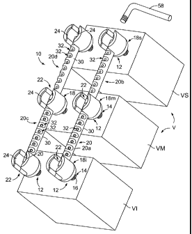
100711 Referring to Figs. 1-5, a first form of a spinal stabilization
system 10 of the
present invention is illustrated secured with a plurality of representative
vertebrae V. As
illustrated, the vertebrae V include an inferior vertebra VI, a medial
vertebra VM, and a
superior vertebra VS. The stabilization system 10 includes a plurality of
anchors 12 so that
a pair of anchors 12 is provided for each vertebra V, as is well-known in the
art. Each
anchor 12 includes a screw 14 having a threaded shank 16 received in its
respective vertebra
V and includes a yoke 18. In some forms, the yoke 18 and shank 16 may be fixed
relative to
each other, such as by the anchor 12 being a unitary component or by being
forming integral.
In other forms, the anchor 12 may be a poly-axial anchor so that the yoke 18
may be
oriented in a desirable manner once the anchor shank 16 is secured with the
vertebra V.
100721 The stabilization system 10 includes spanning structures 20 for
connecting the
vertebra V to control the relative movement therebetween. Each yoke 18
includes a channel
22 into which one or more spanning structures 20 is received for securement
therewith.
Once a spanning structure 20 is properly seated in the channel 22, a
securement (not shown)
generally referred to as a cap is driven atop the spanning structure 20 such
as by being
threaded into arcuate recesses 24 of the yoke 18 and to the sides of the
channel 22.
100731 As best seen in Figs. 2 and 4, each spanning structure 20 is
generally rod-like
with an outer surface 30 with a plurality of cut-outs or scallops 32. The
scallops 32 provide
stress concentrators or, alternatively viewed, regions of lower stiffness for
the spanning
- 17-
CA 02693682 2010-01-11
WO 2009/011845
PCT/US2008/008637
PCT PATENT APPLICATION S Attorney
Docket 88730-400202
structure 20. When the spanning structure 20 is secured with the yokes 18, the
scallops 32
are oriented in a direction in which it is desired to permit greater flexure
between the anchors
12 to which the spanning structure 20 extends. To be clear, the scallops 32
are areas of
reduced cross-sectional area that are eccentrically positioned relative to the
central
longitudinal axis of the spanning structure 20 so that orientation of the
spanning structure 20
provides a distinct direction of lowered stiffness, and so that rotation of
the spanning
structure 20 alters the direction of lowered stiffness.
[0074] As can be seen, a first spanning structure 20a is secured between a
first yoke 181
secured with the inferior vertebra VI and with a second yoke 18M secured with
the medial
vertebra VM while a second spanning structure 20b is secured between the
second yoke 18M
and a third yoke 18S secured with the superior vertebra VS. When secured, the
scallops 32
of the first and second spanning structures 20a, 20b may have different radial
orientations
such that the flexure mechanical characteristics between the first and second
yokes 181 and
18M are different than the flexure mechanical characteristics between the
second and third
yokes 18M and 18S.
[0075] It should also be recognized that the first spanning structure 20a
cooperates with
a third spanning structure 20c while the second spanning structure 20b
cooperates with a
fourth spanning structure 20b to define the mechanical properties between
their respective
vertebrae V; thus, Varying the orientations of scallops 32 for each of the
four spanning
structures 20a-20b serve to provide at least some of the mechanical properties
for the
stabilization system 10 as a whole. It should also be noted that the materials
of the different
- 18-
CA 02693682 2010-01-11
WO 2009/011845
PCT/US2008/008637
PCT PATENT APPLICATION Attorney
Docket 88730-400202
spanning structures 20a-20b may be varied to provide or influence the
mechanical properties
of each.
[0076] In a further form of the spanning structure 20, the scallops 32 are
formed on a
shell member 40, and a core member 42 is received within the shell 40. In
various forms,
the core 42 may be of like or dissimilar materials to influence the mechanical
properties to
provide varying selected or selectable flexure properties, for instance.
[00771 In a preferred form, the core 42 also includes scallops 44 along its
length, as best
seen in Figs. 2 and 4. When the core 42 is received within the shell 40, the
core scallops 44
may be aligned (or misaligned) to varying degrees with the shell scallops 32.
As should be
evident, when the sets of scallops 44, 32 are aligned, such augments the
flexure
characteristics and, more appropriately, lessens the stiffness of the spanning
structure 20 as a
whole in a particular direction. When the scallops 44, 32 are largely
misaligned, the
decrease in stiffness provided by the different scallops 44, 32 is aligned in
first and second
directions. For the scallops 44, 32 merely being partially overlapping or
relatively
juxtaposed, the decrease in stiffness is distributed over the region between
and including the
scallops 44, 32. It should be noted that the scallops 32, 44 may be aligned or
misaligned in
both a radial direction (i.e., orientation in a 360 degree sweep) and in an
axial direction.
[0078] The alignment of the scallops 32, 44 may be selected at any time
prior to, during,
or after implantation (securement in the yokes 18), as well as after the
surgical procedure
itself. To promote such adjustment, the core 42 may be provided with structure
50 on one or
more ends 52 for engaging and rotating the core 42 relative to the shell 40.
- 19 -
CA 02693682 2010-01-11
WO 2009/011845
PCT/US2008/008637
PCT PATENT APPLICATION Attorney
Docket 88730-400202
[0079] As can be seen in Fig. 5, the core 42 includes a socket 56 shaped
for receiving a
key 58 (not shown). As an example, the socket 56 may be hexagonal (Fig. 5) for
receiving a
hexagonal key 58 (Fig. 6). In other forms, the key 58 may have a hook (not
shown) or the
like for axially advancing or withdrawing the core 42 along the axial
direction of the shell
40. In another form, the socket 56 may include a section of internal threading
for threadably
receiving the key 58, the key 58 having slightly undersized threading (Fig. 1)
for easy thread-
receipt and effecting rotation in a single direction when fully advanced in
the socket 56. Due
to the threaded connection, such key 58 enables axial forces to be applied to
the core 42 to
advance/withdraw the core 42 within the shell 40.
[0080] The scallops 32, 44 may be cut at an oblique angle relative to a
circumference of
the shell 40 and/or core 42 so that the scallops 32, 44 may also facilitate or
enable torsional
distortion thereof. The depth, frequency, and/or size of the scallops 32, 44
may be varied
along the length of the shell 40 or core 42 so that the "spring equation" of
the spanning
structure 20 is non-linear, that is, so that the force required to achieve a
certain amount of
bending to the spanning structure 20 increases as the bending increases.
Instead of the
scallops 32, 44, either or both of the shell 40 and/or core 42 may simply be
given a non-
circular cross-section so that the bending characteristics are not the same
throughout a 360
degree sweep.
[0081] Turning now to Fig. 6, the spinal stabilization system 10 is
depicted as
implantated with a layer 60 of a patient's flesh (including the surface skin)
located atop the
stabilization system 10. As can be seen, a small incision 62 may be made in
the layer 60 to
provide a passage or access 64 to the end 52 of a spanning structure 20. The
key 58 may be
- 20 -
CA 02693682 2010-01-11
WO 2009/011845
PCT/US2008/008637
PCT PATENT APPLICATION Attorney
Docket 88730-400202
inserted through the small incision 62 and the access 64 for connection with
the spanning
structure 20 socket 56. Accordingly, a major revision surgical procedure is
not necessary to
alter the mechanical performance characteristics (i.e., flexure or stiffness
of the spanning
structures 20), as such can be done with a minor procedure. It should also be
noted that the
core 42 may be entirely removed from the shell 40, which would also permit a
new core 42
with greater or lesser stiffness to replace the previous core, all without
having to remove the
securements (i.e., caps) from the yokes 18.
[0082] As
discussed above, the materials for the spanning structures 20 may be varied
to provide different flexure or mechanical performance characteristics.
Turning to Fig. 7, a
form of a spinal stabilization system 80 is depicted similar to that of Figs.
1-6, though
simplified to illustrate spanning structures 82 and, in particular, to depict
a first spanning
structure 82a having a first modulus of elasticity and a second spanning
structure 82b having
a second modulus of elasticity that is different from the first, the modulus
of elasticity
determined by the material from which each spanning structure 82a, 82b is
formed. As
noted above, in the event a pair of spanning structures 82 is used in tandem
to span between
two vertebrae V. such as adjacent vertebrae V, the flexure characteristics are
determined by a
combination of the elastic moduli of the two spanning structures 82 of the
pair.
[0083] It
should be noted that reference to flexure characteristics and mechanical
performance characteristics, as used herein, are meant to refer to how a
spanning structure
and/or a stabilization system performs under load, based on inherent materials
properties and
structural geometry. While in biomechanics, flexure and extension are
generally thought of
as being opposite, with respect to curving or bending of a spanning structure,
these terms are
-21 -
CA 02693682 2010-01-11
WO 2009/011845
PCT/US2008/008637
PCT PATENT APPLICATION Attorney
Docket 88730-400202
one and the same. Additionally, these terms are intended in a broad manner to
also include
torsional distortion or twisting. Modulus of elasticity or elastic modulus is
an inherent
property of the material, regardless of shape or geometry. While stiffness and
modulus of
elasticity are typically thought of as linear descriptions of mechanical
behavior dependent on
shape and material, thereby equating them to a spring equation having a spring
constant K
(i.e., Force = K x Change in Length), it should be noted that these terms
herein encompass a
non-linear description of mechanical behavior such that force and distortion
are not in direct
proportion.
[0084] Turning now to Figs. 8-10, a further form of a spinal stabilization
system 100 is
illustrated having spanning structures 102 with different and selectable
flexure
characteristics. Again, the stabilization system 100 is largely similar to the
stabilization
systems 10 and 80, discussed above. However, the flexure characteristics of
the stabilization
system 100 of Figs. 8 are principally determined by the cross-sectional size
of the spanning
structures 102 as a whole between the vertebrae V.
[0085] More particularly, a spanning structure 102a between the superior
and medial
vertebrae VS and VM is approximately twice the cross-sectional size of the
spanning
structure 102b between the medial and inferior vertebrae VM and VI. As best
seen in Fig.
10, the spanning structure 102a, 102b both include portions of a base spanning
structure 104
that extends across and between each of the vertebrae V. However, the superior-
medial
spanning structure 102a additionally includes a secondary spanning structure
106, the
combination of the same with the base spanning structure 104 defining the
flexure
- 22 -
CA 02693682 2010-01-11
WO 2009/011845
PCT/US2008/008637
PCT PATENT APPLICATION Attorney
Docket 88730-400202
characteristics therefor. Accordingly, the stiffness of the superior-medial
spanning structure
102a is greater than the stiffness of the medial-inferior spanning structure
102b.
[0086] To the degree each of the spanning structures discussed herein does
not exceed its
elastic limit (or, more precisely, its change in shape does not exceed, for
any portion thereof,
a change beyond which deformation becomes permanent), such spanning structures
may be
modeled as a spring. However, each of the above-discussed forms of the
spanning structures
provides little, if any, expansion or compression along the longitudinal axial
direction of the
spanning structures.
[0087] Turning now to Figs. 11 and 12, a further form of a spinal
stabilization system
120 is shown having spanning structures 122 that include a coil spring portion
124 that
allows the stabilization system 120 to accommodate expansion and contraction
of the
spanning structure 122 along its longitudinal axis. The stabilization system
120 includes
anchors 12 and yokes 18, like each of the above-described embodiments, the
spanning
structures 122 being received in the yokes 18 and secured therein by a
securement such as a
cap.
[0088] In order to secure the spanning structure 122 with the yokes 18,
each end 126
thereof includes an end fixture 128. The end fixture 128 may have any shape,
provided that
the end fixture 128 is generally sufficiently rigid as to be compressed within
the yoke 18 by
the securement. The end fixtures 128 are illustrated as being generally
octagonal so that flats
130 are formed on the end fixture 128, a pair of the flats 130 contacting the
sides of the yoke
channel 22, a flat 130 contacting the bottom interior of the yoke channel 22,
and a flat 130
being outwardly facing for contact with the cap when secured in the yoke 18.
As noted,
- 23 -
CA 02693682 2010-01-11
WO 2009/011845
PCT/US2008/008637
PCT PATENT APPLICATION Attorney
Docket 88730-400202
other configurations of the end fixture 130 may be provided, such as a square
or circle;
however, the octagonal shape has the benefit of a leading flat 130 that is
shorter than the
width of the yoke channel 22 to assist in initial advancement of the end
fixture 128 into the
channel 22. The octagonal shape also provides the benefit of the flats 130
themselves for
engaging with the yoke 18 and cap, which serves to provide good compressive
contact and
serves to retard rotation of the end fixture 128 within the yoke 18 after
securement.
[0089] Each spanning structure 122 is provided with a single coil spring
124. For the
various spanning structures 122 illustrated, each can be provided with varying
mechanical
performance characteristics. For instance, the effective (i.e., when
implanted) spring
constant for each coil spring 124 can be selected based on the length of the
coil spring 124, a
number of turns in the coil spring 124, a diametral size of the coil spring
124, and pre-
stressing of the coil spring 124 when implanted.
[0090] A surgeon can easily adjust or alter the performance characteristics
by altering the
above aspects of the coil spring 124. As best seen in Fig. 11, each end
fixture 128 is
provided with at least one opening 136. A tool (not shown) can be inserted
into the end
fixture 128 through an end passage 138 and into the opening 136. The tool can
then be used
to rotate the end fixture 128 relative to the other end fixture 128, thus pres-
stressing the coil
spring 124 as well as changing the diametral size and number of coils in the
spring 124. In
one form, a first of the end fixtures 128 may be positioned in a yoke 18,
while the other is
manipulated as described. Alternatively or in addition, the first end fixture
128 may be
secured in a yoke 18, and the other end fixture 128 may be pulled
longitudinally, along the
axis of the spanning structure 120, to remove it from the yoke 18; the end
fixture 128 may
- 24 -
CA 02693682 2010-01-11
WO 2009/011845
PCT/US2008/008637
PCT PATENT APPLICATION Attorney
Docket 88730-400202
then be rotated and returned within its yoke 18 when the desired number of
turns has been
made. In order to perform such, loosening of a cap or securement for the end
fixture 128
that is rotated may be necessary, particularly if such procedure is performed
in a post-
operative procedure.
[0091] While the spanning structures 122 including the coil springs 124
provide
expansion and compression along the longitudinal length, they provide less
stiffness in the
other directions. Accordingly, a core 132 may be inserted within the coil
springs 124. The
cores 132 may be provided with varying mechanical performance characteristics,
as has been
discussed herein, such as by being formed of materials with different elastic
moduli.
[0092] As shown in Fig. 12, the core 132 may span a plurality of vertebrae
V.
Alternatively, the cores 132 may span only to two adjacent vertebrae V. In a
preferred form,
the cores 132 may be removable and replaceable without removal of the
securement and end
fixtures 128. In this manner, the cores 132 may be changed by the above-
described simple
incision procedure. Towards this end, the cores 132 may be provided with
structure
assisting in their removal, such as structure similar to the above-described
socket 56 and key
58.
[0093] In a form similar to the spanning structures 20 or 122, a
stabilization system may
be provided with spanning structures 142 that are essentially tubular casings
144, having a
hollow bore 146, and a plurality of strands 148 of material are received
within the bore 146,
as depicted in Fig. 13. The number and/or size of the strands 148 thus
cooperate with the
casing or sheath 144 to provide the flexure characteristics for the spanning
structure 142. In
general, the strands 148 would generally be rod or wire-like with a constant
diameter and
- 25 -
CA 02693682 2010-01-11
WO 2009/011845
PCT/US2008/008637
PCT PATENT APPLICATION Attorney
Docket 88730-400202
inserted within the casing 144 to provide a desired stiffness. However, the
individual strands
148 may also have non-uniform cross-sections, for the reasons discussed
herein, and/or may
have non-uniform lengths. For the latter, the strands 148 could be staggered
or otherwise
positioned relative to each other so that the combination of the strands 148
and the casing
144, through any particular cross-section, determine the stiffness thereat.
[0094] The number or configuration of the strands 148 may be modified at
any desired
time, such as post-implantation or post-operatively. That is, it may be
convenient to initially
implant and secure the casing 144 with the yokes 18, and then insert the
strands 148.
Furthermore, later minor surgical procedures could be performed to provide
additional
strands 148, or to remove strands 148, based on the conditions experienced by
the patient.
[0095] It is known that the bone-screw interface, such as for a pedicle
screw, improves
over time in the absence (or minimization) of loading on the interface.
Therefore, it may be
desirable for a portion of the stabilization systems to be implanted with
minimal loading on
the anchors 12, and a portion to be subsequently adjusted or added to increase
the loading on
the anchors 12 or the stiffness of the stabilization system.
[0096] For instance, the casing 144 may be implanted (or the above-
described shell 40 or
coil spring 124, for instance) with the bore 146 substantially empty. After a
period of time, a
minor surgical procedure including a small incision proximate the spanning
structure, as is
described for Fig. 6, may be performed to increase the stiffness such as by
inserting strands
148 into the bore 146.
- 26 -
CA 02693682 2010-01-11
WO 2009/011845
PCT/US2008/008637
PCT PATENT APPLICATION Attorney
Docket 88730-400202
[0097] In a reverse manner, decreasing the stiffness of the spanning
structures may be
performed in accordance with that discussed for Fig. 6 by making the small
incision and
removing strands 148 from the bore 146.
[0098] In another form of spinal stabilization system 160, shown in Figs.
14-17, anchors
162 are provided for securing spanning structures 164 having springs. The
anchors 162
include a threaded shank 166 as described above and a head 168 which may or
may not be
polyaxially adjustable, as described. In contrast to the above forms, the head
168 does not
form a yoke 18 having a channel 22, instead having a cylindrical recess 170
defined by an
upstanding collar 172.
100991 An anchor post 174 cooperates with the head 168 for securing the
spanning
structures 164 with the anchors 162. The post 174 includes a widened base 176
received in
the recess 170 and an upstanding post portion 178. The head collar 172 is
threaded (either
internally or externally) for receiving a nut 180 thereon for securing the
anchor post 174 with
the head 168.
[00100] As best seen in Fig. 17, the post portion 178 includes a hollow or
a bore 184 into
which a portion 190 of the spanning structure 164 is received. Specifically,
the portion 190
is a rod-like member linearly advanced through a bore 184 of a first anchor
162a and into a
bore 184 of a second anchor 162b, representatively noted in Fig. 14. The post
portion 178
receives a set screw 179 that may be driven into the post portion 178 to reach
the bore 184
and apply pressure against the portion spanning structure rod 190.
[00101] The spanning structures 164 each include a first spring 194 and a
second spring
196 located, sheath-like, around the rod portion 190. The first spring 194 has
a smaller
- 27 -
CA 02693682 2010-01-11
WO 2009/011845
PCT/US2008/008637
PCT PATENT APPLICATION Attorney
Docket 88730-400202
diameter than the second spring 196 so that the second spring 196 is also
positioned, sheath-
like, around the first spring 194. The first spring 194 is configured to be
compressed from a
natural position when the stabilization system 160 is loaded so that the
anchors 162 between
which the first spring 194 spans are moved toward each other. The second
spring 196 is
configured to be stretched or expanded from a natural position when the
stabilization system
160 is loaded so that the anchors 162 are moved away from each other. In order
to maintain
the second spring 196 with the anchors 162, an end 198 of each second spring
196 includes
an end loop 200 that may be secured around the post portion 178 and, in
particular, in an
annular groove (not shown) formed in the post portion 178.
[00102] As described above, one manner of selectively varying the stiffness
of the second
(expansion) spring 196 coil is by rotation of the ends 198 to enlarger or
contract the diameter
of the spring 196, thereby changing its spring equation. It should be noted
that the size of
the coils may be varied over the length of the spring 196 to give the spring
non-linear
spring/flexure characteristics. Similarly, the spring properties of the first
(compression)
spring 194 may be altered.
[00103] It should also be noted that the stabilization system 160 may also
be adjusted
through a small incision formed proximate an anchor 162 in a manner similar to
that
described for other forms herein. Removal of the rod portion 190 and release
of one of the
ends 198 of the second spring 196 allows the first spring 194 to be removed
and changed, for
instance, and the ends 198 may also be subsequently rotated and replaced on
the post portion
178.
- 28 -
CA 02693682 2010-01-11
WO 2009/011845
PCT/US2008/008637
PCT PATENT APPLICATION Attorney
Docket 88730-400202
[00104] Turning now to Figs. 18-21, forms of spinal stabilization systems
are shown
using fluid and piston assemblies, fluid referring to both gasses and liquids.
As will be
discussed in greater detail below, a first form of such systems is shown in
Figs. 18 and 19 as
stabilization system 220 having a plurality of anchors 12 and spanning
structures 222, each
having a gas-filled piston 224 assembly thereon. As will also be discussed
below, Fig. 20
and 21 depict a stabilization system 250 having a plurality of anchors 12 and
spanning
structures 252, each having a liquid filled piston assembly 254 thereon.
1001051 Turning to Figs. 18 and 19, the piston assembly 224 may be referred to
as a
pneumatic assembly including a fluid chamber (not shown) and a piston head
(not shown)
reciprocable within the chamber. The fluid chamber is filled with gas so that
movement of
the piston head therewithin serves to either compress or expand the gas within
the chamber.
Accordingly, to some degree, the gas acts as a spring.
[00106] The "stiffness" of the gas acting like a spring can be modified by a
surgeon user.
In a preferred form, an end 226 of each piston assembly 224 includes a port
228 for
connection with an external fluid reservoir (not shown) that allows a surgeon
to pump in
additional fluid or gas, or allows the surgeon to bleed off a portion of the
gas. As other
embodiments discussed herein, such pressure adjustment may be performed post-
operatively, such as through a small incision or via a hypodermic needle
injection.
Additionally, a reservoir may be implanted subcutaneously that allows for
manual pumping
of the reservoir, through the skin, and pressure relief. For instance, the
reservoir may be a
compressible bladder-type device connected via a one-way valve to inject fluid
into the
- 29 -
CA 02693682 2010-01-11
WO 2009/011845
PCT/US2008/008637
PCT PATENT APPLICATION Attorney
Docket 88730-400202
piston chamber, and a second one-way valve may be provided for reducing or
bleeding fluid
from the piston chamber into the bladder.
[001071 The stabilization system 220 may be implanted with little or no gas
so that the
bone-anchor interface is able to heal prior to loading of the stabilization
system 220, as has
also been discussed above, and subsequently the piston assembly 224 may be
pressurized as
desired. As can be seen, different piston assemblies 224 of the stabilization
system 220 may
be provided with different internal pressures within the piston chamber so
that each piston
assembly 224 has a selected "stiffness."
[00108] The stabilization system 250 of Figs. 20 and 21 is similar in
operation to that of
Figs. 18 and 19. The stabilization system 250 is a hydraulic system utilizing
fluid in the
form of a liquid that is incompressible or minimally compressible within
piston assemblies
252. Accordingly, the the piston assembly 252 is highly resistant to
compression or
expansion. While this may be viewed as a detriment, it is noted that pumping
in or bleeding
off of liquid from a port 254 located on an end 256 of the piston assembly 252
provides a
high degree of predictability for the performance of the piston assembly 252.
In increasing
or decreasing the liquid volume, the distance between the anchors 12 to which
the piston
assembly 252 is secured is relatively easily determined by the surgeon; for
instance, a
surgeon may be using the stabilization system 250 to relieve pressure on a
damage
intervertebral disc that is causing pressure and pain on the spinal column,
and shifting of
vertebrae away from each other by increasing the liquid volume in the piston
assembly 252
is evident.
- 30 -
CA 02693682 2010-01-11
WO 2009/011845
PCT/US2008/008637
PCT PATENT APPLICATION Attorney
Docket 88730-400202
[00109] In a variation of the stabilization system 250, the piston assembly
252 may be
provided with a dashpot damping structure (not shown) within the fluid (or,
more
appropriately within the liquid-filled fluid chamber of the piston assembly
252). In this
manner, controlled and moderate compression or expansion of the piston
assembly 252 is
permitted, yet fast or sudden moves are resisted (in proportion to the square
of the velocity,
as is known in the art). In a further variation, the piston assembly 252 may
be provided with
an elastically compressible member or material (not shown), either externally
located
between the piston assembly 252 and an anchor 12 or internally within the
piston fluid
chamber. In still another variation, the piston assembly 252 may have a fluid
of mixed
phases, either of same or different material, so that the piston assembly 252
includes the
compressibility of a gas form and the incompressibility of a liquid form, and
the liquid and
gas may be adjusted as desired.
1001101 As described, the piston assemblies 224 and 252 may be compressed
only in their
longitudinal directions, though they would have limited flexibility in other
directions.
Accordingly, the piston assemblies 224, 252 generally only permit
flexure/compression in
the anterior-posterior directions. The piston assemblies 224, 252 may be
calibrated so as to
select a desired amount of "stiffness" in their compression. If a compressible
fluid were
utilized, the "stiffness" may be variable (as opposed to linear based on
Boyle's law).
Additionally, the fluid may be a non-Newtonian fluid so that shear rate versus
force is non-
linear, or may have a damper effect by using a fluid of high viscosity and/or
internal damper
structure. The stiffness characteristics of different piston assemblies in the
spinal
stabilization systems may vary from assembly to assembly so that, for
instance, the stiffness
-31 -
CA 02693682 2010-01-11
WO 2009/011845
PCT/US2008/008637
PCT PATENT APPLICATION Attorney
Docket 88730-400202
between two vertebral levels may have a first set of characteristics, while
the stiffness
between two other vertebral levels may have a second set of characteristics.
[00111] The above-noted reservoir may, alternatively, be located sub-
cutaneously so that
post-operative adjustment can be made without revision surgery. In some forms,
separate
valves may be provided on the piston assemblies for increasing pressure and
for decreasing
pressure. Additionally, the above-described keys or tools for adjusting the
spanning
structures or the mechanical performance characteristics thereof may also be
joined with the
spanning structures and implanted such that non-surgical adjustment of the
keys or tools may
be had via manipulation through the skin.
[00112] It should be noted that, as described, forms of the stabilization
system described
herein can be adjusted by a simple, relatively straightforward revision
procedure, as
described for the form of Fig. 6. The spanning portions described herein allow
a continuous
adjustment and selection (as opposed to an incremented selection based on rod
diameter) of
the stiffness or modulus of elasticity (or set of characteristics relating
thereto). Additionally,
spanning portions extending between an inferior vertebra and a second (medial)
adjacent
vertebra may have a first stiffness, while spanning portions extending between
the medial
vertebra and an adjacent superior vertebra may have a second stiffness or
characteristics
relating thereto.
[00113] A variety of forms of spanning structures are illustrated in Figs.
22A-22C. A
spanning structure 270 may be constructed of various layers of material, two
or more of
which have differing linear moduli of elasticity. The thickness of the layers
may be selected
to impart a varying spring equation to the spanning structure 270 over its
longitudinal length.
- 32 -
CA 02693682 2010-01-11
WO 2009/011845
PCT/US2008/008637
PCT PATENT APPLICATION Attorney
Docket 88730-400202
For instance, a central core portion 272 may be formed of material with a
first modulus of
elasticity, and the central core portion may have a varying cross-sectional
shape so that the
spring equation for the core portion 272 varies over its longitudinal length.
In order to
maintain a constant outer diameter to the spanning structure 270, a layer 274
of constant
outer diameter may be applied over the core portion, the layer 274 having a
varying inner
diameter corresponding to the outer diameter of the core portion 272. In this
embodiment,
the material of the layer portion 274 has an elastic modulus different from
that of the core
portion 272, and the materials and geometries of the core and layer (or
layers) are selected to
control or provide a specific set of flexure/bending characteristics.
[00114] In another form, a spanning structure 280 may have a hollow core or
bore 282 of
varying inner diameter. For instance, the bore 282 may have a conical shape
(Fig. 21B), a
double-frustum shape (Fig. 21C), or another shape. The varying inner diameter
allows for
the bending of the spanning structure 280 rod to be non-linear proportion to
the force
applied. In some forms, the above-described scalloping 32, 44 may be formed on
the interior
surface of the inner bore 282.
[00115] It should be noted that any of the above forms may be provided with
shock
absorbers or the like, such as at an interface between the spanning structures
and the anchors.
For instance, the spanning structures and the anchors may be joined by an
elastomeric or
polymeric coupling.
[00116] In variations of the present invention, the effective bending
characteristics of
spanning structures may be varied by varying their geometry, structure, and/or
composition.
For instance, a single (first) spanning portion may have a varying cross-
section over its
- 33 -
CA 02693682 2014-07-21
67263-56
length, and/or the first spanning portion may have varying cross-section in
comparison to a
second spanning portion. In some forms, the spanning portions may be
constructed as
composite or layered member to impart desired flexure characteristics,
including varying the
thickness or size of layers so that the flexure characteristics are non-
linear.
[00117j While
the invention has been described with respect to specific examples
including presently preferred modes of carrying out the invention, those
skilled in the art will
appreciate that there are numerous variations and permutations of the above
described
systems and techniques that fall within the scope of the invention.
- 34 -