Note: Descriptions are shown in the official language in which they were submitted.
CA 02693893 2010-01-15
WO 2009/012371 PCT/US2008/070305
OPERATION OF A REMOTE MEDICATION MANAGEMENT SYSTEM
CROSS-REFERENCE TO RELATED APPLICATIONS
(0001] The instant application is a continuation-in-part of prior U.S. Patent
Application No.
11 /685,191 entitled "Remote Medication Management System" and filed March 12,
2007, which
prior application is a continuation-in-part of prior U.S. Patent Application
Serial No. 11/013,285
entitled "Integrated, Non-Sequential, Remote Medication Management and
Compliance System"
and filed December 15, 2004, which prior application claims the benefit of
Provisional U.S.
Patent Application Serial No. 60/565,221 entitled "Non-Sequential Medication
Delivery System"
and filed April 24, 2004. The entirety of each of these prior applications is
incorporated herein
by this reference.
FIELD OF THE INVENTION
[0002] The disclosure relates generally to systems for facilitating patient
medication compliance,
and more particularly to apparatus and methods for remotely delivering
individual doses of
therapeutic products to a patient.
BACKGROUND OF THE INVENTION
100031 Patient non-adherence to prescribed medication regimens is a
significant problem which
undermines efforts to manage chronic illnesses. Factors such as an overall
increase in outpatient
medical procedures have contributed to an increased level of responsibility
being placed upon
patients and caregivers in the administration of prescription drugs. While
estimates of medication
non-adherence in remote, residential settings typically range from 30-60%,
depending on the
disease state, elderly patients average a rate of more than 45% due in part to
visual, auditory, and
cognitive impairments. Drugs not taken, or taken incorrectly, incur the same
health care costs as
CHICAGO/#1667512.1
CA 02693893 2010-01-15
WO 2009/012371 PCT/US2008/070305
fully adherent regimens, but without the expected medical outcome. The
consequences of non-
adherence can be significant, resulting in emergency room visits, extended
hospitalizations, long-
term care facility admissions, and death.
[0004] The ability to comply with a medication regimen is complicated in
situations where
dosing amounts change over time. For instance, prescribed dosing amounts are
frequently a
function of ongoing laboratory tests that determine the patient's status.
Likewise, appropriate
dosage amounts are determined in accordance with a patient's health condition
and must reflect
unexpected changes in such condition. In these situations, healthcare
practitioners such as
physicians, pharmacists, and nurses need to be able to adjust a patient's
dosage as quickly as
possible. Medication compliance is particularly important when narrow
therapeutic index drugs
are prescribed, as over-medicating or under-medicating a patient can cause
serious side effects,
illness and even death.
100051 A fairly large number of devices have been developed for prompting a
patient to take a
prescribed dose of medication at the correct times. Existing devices function
primarily to remind
patients when to take a particular medication and to sequentially deliver that
medication in
accordance with a predetermined schedule. Many of these devices are designed
to expel
medication automatically, in accordance with a predetermined schedule. In this
regard, the
devices do not provide adequate protection against both under-dosage and over-
dosage. If the
patient fails to take the medication according to schedule, the devices
continue to expel
medication at set intervals based on the premise that the patient took all
previous medications
appropriately. Such a situation greatly enhances the risk of non-compliance,
wherein a patient
takes less medication than is prescribed. Conversely, if the patient does not
take the medication
2
CHICAGO/# 1667512.1
CA 02693893 2010-01-15
WO 2009/012371 PCT/US2008/070305
according to schedule, but too close to the time for taking subsequent
medication, the patient
faces the risk of over-dosage.
[0006] Certain devices incorporate means for retrieving pills which are
discharged but not
removed from the device. Some of these devices provide notification to
caregivers of a patient's
failure to take medication according to schedule. Other devices have been
integrated into
comprehensive medication management and delivery systems in which a healthcare
practitioner
remotely monitors information regarding patient compliance and non-compliance
with a
medication regimen. While these systems enhance patient compliance with a
prescribed
treatment regimen, they are deficient in one notable respect, that is, they do
not provide a
mechanism by which a patient's failure to take a scheduled dose of medication
can be rectified in
minutes. As such, the systems do not overcome the problem of patient under-
dosage and over-
dosage. This drawback is particularly significant with respect to high risk
patient populations,
where patients frequently suffer from cognitive, visual and/or auditory
impairments which
contribute to non-adherence.
[0007] An additional shortcoming of the existing systems is that they fail to
provide a
mechanism by which a prescribed dosage can be remotely adjusted in minutes, in
response to an
unexpected change in a patient's health condition. Although the systems allow
a healthcare
practitioner to communicate a change in dosing amount to the patient, they do
not enable the
practitioner to immediately and remotely change, adjust or discontinue a
prescribed dosage.
There is often a delay of several hours, and in some cases, several days,
before a patient is able to
procure the new dosage. During this period, the patient may be confused as to
the correct
regimen and continue to take the discontinued dosage. In addition, because a
new prescription is
3
CHICAGO/#1667512.1
CA 02693893 2010-01-15
WO 2009/012371 PCT/US2008/070305
required every time a dose is adjusted, the patient is must travel to a
physician's office and/or a
pharmacy. Although this may pose an inconvenience to some patients, this is
particularly
disadvantageous to mobility-impaired patients and is a major contributor to
drug non-
compliance. Frequently the patient's condition deteriorates, as the patient is
unable to continue
the correct course of treatment.
[0008] A further drawback of the conventional systems is that prescriptions
are filled in either
standard thirty day or sixty day allotments. With such means, there is no
accurate way to
inventory pharmaceuticals and/or to audit patient compliance or consumption of
the product.
This is due in part to the fact that the pharmaceuticals are dispensed in a
lot, and not every pill or
dose is separately bar coded and traceable.
100091 The above-described medication management and delivery systems suffer
from a still
further limitation, namely, they fail to establish a secure data communication
process to deploy
communications to and from a remote medication delivery device based in a
patient's home
while protecting patient privacy. Maintaining patient privacy in the data
communication process
has to date been a formidable challenge. Moreover, an increasing number of
regulations
regarding the maintenance and storage of patient data have been enacted in
response to the
Health Insurance Portability Accountability Act. Accordingly, there is a need
and a desire for a
cost-effective system that quickly addresses a patient's non-compliance with a
prescribed drug
regimen in real time and minimizes disruptions to a patient's course of
treatment while protecting
patient information.
4
CHICAGO/# ] 667512.1
CA 02693893 2010-01-15
WO 2009/012371 PCT/US2008/070305
SUMMARY OF THE INVENTION
[0010] The present disclosure describes a medication management and compliance
system for
enabling a healthcare practitioner to remotely manage and deliver sealed unit
dose packages of
prescription and non-prescription therapeutic products to a patient, on a dose
by dose basis, and
in a manner that provides immediate confirmation that a dose has been
delivered. Clinical
software is used for storing patient prescription and dosing regimen
information, enabling
authorized healthcare personnel to remotely deliver a unit dose therapy to a
patient and monitor
patient compliance with a dosing regimen, without violating patient privacy.
The system includes
delivery apparatus located in proximity to the patient, wherein the delivery
apparatus is remotely
coupled to the clinical software and to a control center by means of a data
communications
network.
[0011] In one example, the delivery apparatus features a controller for
executing command
signals received from the control center and clinical software, as well as a
storage area for
storing unit dose packages. The apparatus delivers a sealed, unit dose package
to the patient at a
scheduled dosing time, in response to a command signal. The present system
enables the
healthcare practitioner to remotely deliver any unit dose package stored
within the delivery
apparatus to a patient, in non-consecutive fashion, without being limited by a
predetermined
sequence. In this way, medication dosage amounts can be instantaneously
tailored to adapt to
fluid medical conditions. In one example, a fully integrated, real-time, non-
sequential,
comprehensive medication management and compliance system can accurately
deliver both
custom packaged and commercially available sealed unit dose and unit-of-issue
therapeutic
products to patients.
CHICAGO/# 1667512.1
CA 02693893 2010-01-15
WO 2009/012371 PCT/US2008/070305
BRIEF DESCRIPTION OF THE DRAWINGS
[0012] FIG. 1 is a perspective view of a non-sequential medication delivery
module in
accordance with one embodiment of the invention.
[0013] FIG. 2 is a block diagram showing a non-sequential medication delivery
module with
remote monitoring and access control in accordance with an embodiment of the
invention.
[0014] FIG. 3 is an assembly view of one example of a non-sequential
medication delivery
module in accordance with an embodiment of the invention.
[0015] FIGS. 4 and 5 are cutaway views showing the friction drive assembly and
storage
elevator in accordance with one embodiment of the invention.
100161 FIG. 6 is a perspective view depicting the storage apparatus in
accordance with the
present invention.
[0017] FIG. 7a is a cross-sectional view illustrating the mechanism of
operation of the latch
apparatus. FIG. 7b is an exploded view of the latch apparatus in an unlocked
position.
[0018] FIG. 8 is a cross-sectional view illustrating the mechanism of
operation of the friction
drive assembly with respect to an incoming medication carrier in accordance
with an
embodiment of the invention.
[0019] FIG. 9a is a cross-sectional view of a medication carrier fully
inserted into the delivery
module. FIG. 9b is an exploded view of the latch apparatus in a locked
position.
[00201 FIG. 10 is a cross-sectional view illustrating the mechanism of
operation of the carriage
drive assembly in accordance with one embodiment of the invention.
6
CHICACO/#t ] 6675 12.1
CA 02693893 2010-01-15
WO 2009/012371 PCT/US2008/070305
[0021] FIG. 11 is a cross-sectional view illustrating the operation of the
storage elevator and
associated linear motion assembly in accordance with an embodiment of the
invention.
[0022] FIG. 12a is a cross-sectional view showing the ejector assembly in a
rest position and
operative position for ejecting a unit dose package from a medication carrier
in accordance with
one embodiment of the invention.
[0023] FIG. 12b is an assembly view of the ejector assembly shown in FIG. 12a
in accordance
with an embodiment of the invention.
100241 FIG. 13 is a cross-sectional view showing the ejected unit dose package
of FIG. 12a
along with previously ejected unit dose packages.
[0025] FIGS. 14 and 15 depict medication carriers containing unit dose
packages of varying
strengths in accordance with the present invention.
[0026] FIGS. 16-20 are electrical schematics illustrating various operations
of the non-sequential
medication delivery module in accordance with the present invention.
100271 FIGS. 21 a, b and c are perspective views of medication carriers
containing 32, 20 and 16
stalls, respectively, for accommodating different sized unit dose packages.
[0028] FIGS. 22-23 and 25-26 are flow charts illustrating the operations of
the non-sequential
medication delivery module and compliance system of the present invention.
[0029] FIG. 24 is a flow chart illustrating the process that may take place to
suitably deliver a
prescribed dosage to a patient in accordance with an embodiment of the
invention.
7
CHICAGO/# 1667512.1
CA 02693893 2010-01-15
WO 2009/012371 PCT/US2008/070305
[0030] FIGS. 27-31 are examples of worksheets that appear on the computer
monitor of
healthcare personnel.
[0031] FIG. 32 is a perspective view of a partially assembly of an alternative
embodiment of a
medication delivery unit.
[0032] FIG. 33 is a partially exploded, perspective view of an x-axis assembly
in accordance
with the alternative embodiment of a medication delivery unit of FIG. 32.
[0033] FIGs. 34 and 35 are front perspective views of the x-axis assembly of
FIG. 33.
[0034] FIG. 36 is a rear perspective view of the x-axis assembly of FIG. 33.
[0035] FIG. 37 is a partially exploded, perspective view of a y-axis assembly
in accordance with
the alternative embodiment of a medication delivery unit of FIG. 32.
[0036] FIGs. 38 and 39 are rear perspective views of the y-axis assembly of
FIG. 37.
[0037] FIG. 39A is a bottom perspective view of an alternative punch tool for
use with the y-axis
assembly of FIG. 37.
[0038] FIG. 40 is a partial cutaway, perspective view of a z-axis assembly in
accordance with
the alternative embodiment of a medication delivery unit of FIG. 32.
[0039] FIG. 41 is a perspective view of an exemplary carriage for use in a
medication delivery
unit.
100401 FIGs. 42 and 43 are magnified views from various perspectives
illustrating in greater
detail a holding mechanism of the exemplary carriage of FIG. 41.
8
CHICAGO/# 1667512.1
CA 02693893 2010-01-15
WO 2009/012371 PCT/US2008/070305
100411 FIG. 44 is a perspective view of an exemplary medication carrier
comprising a plurality
of unit dose packages in two-dimensional arrangement for use in a medication
delivery unit.
[0042] FIG. 45 is a top magnified view illustrating in greater detail various
features of the
exemplary medication carrier of FIG. 44.
100431 FIG. 46 is a flowchart illustrating exemplary processing concerning
delivery of
medications by a medication delivery unit.
10044] FIG. 47-49 are flowcharts illustrating various exemplary embodiments of
handling of
input medication carriers.
[0045] FIGs. 50-52 are flowcharts describing various exemplary embodiment
concerning
condition testing of unit dose packages in medication carriers.
[0046] FIGs. 53-55 are schematic illustrations of various exemplary unit dose
package condition
testing techniques in support of the embodiments described with reference to
FIGs. 50-52.
100471 FIG. 56 is a flowchart illustrating various exemplary embodiments of
handling of stored
medication carriers.
[0048] FIG. 57 is a flowchart illustrating an exemplary embodiment for
providing packaging
instructions for medication.
[0049] FIG. 58 is a flowchart illustrating an exemplary embodiment for
handling adverse power
conditions at a medication delivery unit.
9
CHICAGO/#1667512_1
CA 02693893 2010-01-15
WO 2009/012371 PCT/US2008/070305
100501 FIG. 59 is a flowchart illustrating an exemplary embodiment for
handling of expired
medications in a medication delivery unit.
[0051] FIG. 60 is a flowchart illustrating an exemplary embodiment for
handling modifications
to dosing regimen for a medication delivery unit.
[0052] FIG. 61 is a flowchart illustrating an exemplary embodiment for
handling of unscheduled
dispensing requests received by a medication delivery unit.
100531 FIG. 62 is a block diagram illustrating the system of FIG. 2 in greater
detail.
100541 FIG. 63 is a block diagram illustrating software architecture of the
system of FIG. 2
according to a presently preferred embodiment in greater detail.
[0055] FIGs. 64-84 illustrate various exemplary graphical user interfaces that
may be employed
in connection with software used by users at remote unit sites, for example,
clinical facilities
and/or pharmacies.
DETAILED DESCRIPTION OF THE PRESENT EMBODIMENTS
[0056] The present invention provides a fully integrated, real-time, non-
sequential medication
management and compliance system for prompting a patient remote from a
clinical environment
to take medication in accordance with a prescribed schedule. A principal
advantage of the
delivery module of the present invention is that it implements a prescribed
medication regimen
by delivering a selected unit dose package of medication to a patient upon
receipt of an
encrypted command signal and patient confirmation. These multiple safeguards
ensure that the
patient receives the prescribed medication at the correct dosing times. In
this manner, the
CHICAGO/#1667512.1
CA 02693893 2010-01-15
WO 2009/012371 PCT/US2008/070305
invention enhances patient compliance and allows for chronotherapeutic
applications that
maximize medication benefits and minimize medication side effects. Also
significant is the fact
that command signals are securely transmitted to and from the delivery module
without
compromising patient privacy in any way.
10057] A further advantage of the present invention is that it enables a
healthcare practitioner to
remotely monitor patient compliance with a prescribed medication regimen and
receive rapid
notification of non-compliance. Most notably, the healthcare practitioner can
promptly adjust the
patient's treatment plan to accommodate a missed dosage or to reflect other
fluid medical
conditions, such as an unexpected change in the health status of the patient.
Where necessary,
dosage adjustments can be made immediately, without the need for a new
prescription. As such,
the invention minimizes any loss of time which may complicate non-compliance
and reduces
medication waste by eliminating the need for a patient to discard remaining
doses in the event of
a dose adjustment.
100581 A still further advantage of the invention is that it protects the
patient from adverse drug
reactions and related consequences of over- and under-medicating by ensuring
that the patient
remains within recommended therapeutic levels. The patient receives a required
dosage at the
proper time, thereby reducing the incidence of emergency room visits and
hospital admissions
occasioned by non-adherence to a prescribed drug regimen or other delays in
the administration
of prescribed medication. In addition, unanticipated visits to health care
providers are reduced,
thereby reducing overall health care costs. This cost-effective system can be
used by healthcare
practitioners operating in a variety of settings.
11
CH ICAGO/# 1667512.1
CA 02693893 2010-01-15
WO 2009/012371 PCT/US2008/070305
[0059] Referring now to the Figures, there is shown in FIG. 2 an overview of
the system of the
present invention. A control center 101, such as a facility operated by
INRange Systems, Inc.,
stocks custom packaged and prepackaged, unit dose prescription and non-
prescription medical
products, pharmaceuticals and nutraceuticals from various drug manufacturers
and suppliers.
Such therapeutic products include, but are not limited to, solid orally
consumed doses, liquid
orally consumed dosages, and injection devices that contain doses that are
delivered or
administered at the point of care. It will be understood that the term
"medication" as used herein
is intended to include individual, unit-of-issue doses of prescription and non-
prescription
medications, medical supplies, pharmaceuticals and nutraceuticals, in a
variety of dosage forms
and strengths, including single and multiple compound medications. Specific
examples include
pills, tablets, capsules, suppositories, inhalers, lotions, pre-filled
syringes, powders, suspensions,
and diagnostic materials such as blood testing strips. At the control center
101, the typically foil-
wrapped or blister-packed unit dose packages 27 are inserted into individual
stalls 28 of one of
several different medication carriers 26, each carrier being designed and
sized to accommodate
almost any commercially available unit dose package 27.
100601 Exterior dimensions of the medication carrier 26 can be slightly
varied, but must be
configured to allow the carrier 26 to easily fit within the delivery module
33. An electronic code
29, such as a bar code or radio frequency identification tag, is affixed to
each medication carrier
26. The electronic code 29 identifies the carrier type and configuration and
provides medication
related information, based on a unique identifier such as a serial number. The
encoded data is
programmed into the control center 101 computer database 35, enabling the
control center 101 to
12
CHICAGO/# 1667512.1
CA 02693893 2010-01-15
WO 2009/012371 PCT/US2008/070305
accurately track and account for each unit dose package 27 at all times, in
conjunction with the
delivery module 33, as described below.
[0061] Referring to FIG. 15, the medication carrier 26 includes a receptacle
for holding
individual, unit dose packages 27 in a non-sequential fashion. Standard unit
dose packages 28
normally include a plastic bubble for holding the unit dose therapy and a seal
fabricated from
paper or foil laminate for retaining the unit dose within the plastic bubble.
"Identifying indicia"
31 such as, for example, an electronic code and human readable information, is
imprinted on the
seal of the unit dose package 27 to denote the medication contained in such
package. The
medication carrier 26 is designed to permit the identifying indicia 31 to be
electronically read by
a bar code scanner 98, optical recognition scanner, radio frequency scanner or
other such device,
without removing the unit dose packages 27 from the medication carrier 26. The
medication
carrier 26 allows an individual, unit dose package 27 to be remotely and non-
consecutively
accessed and discharged from the carrier 26 without disrupting the other unit
dose packages 27
contained therein. In an embodiment, the unit dose may be discharged from its
unit dose package
27 without disrupting other unit dose packages 27 in a medication carrier 26.
100621 As shown in FIG. 21b, the medication carrier 26 may include 32 stalls
arranged in four
rows of eight stalls 28. In this arrangement, the carrier 26 stores medication
for up to 30 calendar
days and provides additional surfaces for affixing a label containing a unique
electronic identifier
29. FIGS. 21a and 21c illustrate medication carriers 26 having 20 and 16
stalls, respectively,
sized and shaped to accommodate larger unit dose packages 27. Each stall 28 of
the medication
carrier 26 includes retaining means 30 for holding the sealed, unit dose
package 27 within the
stall 28 until a scheduled dosing time. At such time, the unit dose package 27
is expelled through
13
CH ICAGO/# 1667512.1
CA 02693893 2010-01-15
WO 2009/012371 PCT/US2008/070305
an aperture in said stall 28. In an embodiment, a unit dose may be expelled
through the aperture
in the stall 28 and the unit dose package 27 may remain.
100631 A printable surface containing identifying indicia is provided on the
upper surface of the
medication carrier 26, along its peripheral edges. The printable surface
features location markers
such as, for example, infrared absorbent ink dots which indicate certain
points of interest on the
carrier 26.
[0064] Normally, the delivery module 33 is remotely located from a clinical
facility where
healthcare personnel are based such as, for example, a physician's office,
pharmacy, pharmacy
benefit manager (PBM), hospital, outpatient clinic, nursing station, assisted
living facility or
long-term care facility. Each clinical facility is equipped with a computer
that includes, for
example, a standard microprocessor, input-output circuits, a memory for
storing patient records
including prescription and dosing schedules, a ROM for storing the operating
program and other
system information, and a monitor for receiving visual feedback. Software 32
such as the
Fulfillment, Adjustment and Compliance Tracking System (FACTTM), commercially
available
from INRange Systems, Inc., operates on computer servers at the clinical
facility. Patient
information is accessed by way of the software's 32 user interface 100, which
features a
complement of menu-driven worksheets that appear on the monitor of a
designated healthcare
practitioner (FIGS. 27-31).
[0065] The user interface 100 enables the healthcare practitioner to remotely
and actively treat a
patient by entering appropriate instructions into his/her computer terminal
using a keyboard,
mouse or other input device. The healthcare practitioner may, for example,
input or retrieve
prescription information, configure formularies or therapeutic regimens,
remotely schedule a
14
CHICAGO/#1667512.1
CA 02693893 2010-01-15
WO 2009/012371 PCT/US2008/070305
new regimen, monitor patient compliance with a dosing regimen, or modify the
dosage amounts
of an existing regimen. The entered instructions are transmitted to the
control center 101, where
the instructions are interpreted and routed to the appropriate delivery module
33 based on a
unique identifier assigned thereto. The user interface 100 also displays real-
time notification of
dosage delivery results communicated to the clinical software 32, enabling the
healthcare
practitioner to take immediate action, if necessary.
100661 The clinical software 32 is securely installed within the confines of
each clinical facility
and utilizes the facility's network security 34 policies and procedures to
authenticate users and
network access to patient data. As described below, the control center 101 has
no access to
patient identifiable information and cannot in any way determine the identity
or location of any
patient utilizing the delivery module 33. This secure technical and physical
information
infrastructure is in accord with the Health Insurance Portability and
Accountability Act
(HIPAA).
[0067] Control software 35 programmed to constantly monitor for signals from
both the clinical
software 32 and delivery module 33 is installed on computer servers based at
the control center
101. The control software 35 administers the various treatment instructions
entered by the
healthcare practitioner, but does not implicate patient information stored
within the software
database 32 of the clinical facility. In general, the control software 32
records and stores
information related to the operation and contents of the delivery module 33,
such as the types
and locations of medication carriers 26 stored within the module 33, a
complete inventory of the
unit dose packages 27 contained within each medication carrier 26, and a
history of all dose
administration operations over a set time period. This record keeping and
inventorying function
CH ICAGO/# l 667512.1
CA 02693893 2010-01-15
WO 2009/012371 PCT/US2008/070305
may be achieved, in part, through the use of electronic coding and other
identifiers which are
assigned to the delivery module 33, medication carriers 26 and unit dose
packages 27,
respectively. The identifiers enable the control center 101 to correlate a
particular medication
carrier 26 to the inventory of unit dose packages 27 contained therein, with
the assistance of
electronic code scanners 92, 98 located within the delivery module 33 for
imaging and
transmitting encoded information to the controller.
[0068] A unique identifier such as a serial number (Unit Identification
Number) is typically
programmed into the delivery niodule 33 at the time of manufacture. Similarly,
identifying
indicia 31 (FIG. 14), including an electronic code and human readable
information, is imprinted
on the seal of each unit dose package 27 by the drug manufacturers or
repackagers. The
electronic code 31 identifies the package 27 contents, including, for example,
the medication
name, dosage strength, lot number, expiration date, national drug code number
(NDC), a unique
package serial number, a quantity within a unit dose package, a quantity
within a medication
carrier and whether a unit dose package comprises a fractional portion of a
unit dose (e.g., a half,
quarter, etc. portion of a pill). A plurality of unit dose packages 27
representing a prescribed
course of medication are placed into the stalls 28 of a medication carrier 26,
in any order. The
unit dose packages 27 need not be organized chronologically, as is required in
the existing
dosage delivery systems, since each package 27 is randomly accessed and
retrieved. The
identifying indicia 31 on the seal of each unit dose package is scanned into
the control center
computer so that an audit trail of each package 27 is maintained.
[00691 The control software 35 assigns a unique identifier 29, such as a
serial number, to the
medication carrier 26. The identifier 29 correlates the medication carrier 26
to the inventory of
16
CHICAGO/# 1667512.1
CA 02693893 2010-01-15
WO 2009/012371 PCT/US2008/070305
unit dose packages 27 contained therein and denotes the contents and location
of each unit dose
package 27. The carrier identifier 29 is reflected within one or more
electronic codes which are
printed onto a label and affixed to separate locations on the medication
carrier 26. This
redundancy ensures that at least one electronic identifier 29 is accessible to
a code reader 92, 98.
This information is stored within the control software database 35.
[0070] As discussed above, the unit dose packages 27 are placed into one of
several different
medication carriers 26, according to the size and configuration of the package
27. For instance,
packages containing syringes are typically placed in a medication carrier 26
having longer and
wider cells, while packages of oral solid doses are normally placed in a
carrier 26 containing
smaller cells. Position coordinates, based on the internal geometry of the
medication carrier 26,
are stored in the control software database 35 to pinpoint the location of
each unit dose package
27 within the carrier 26. These coordinates are also reflected in the
electronic identifier label 29
that is affixed to the medication carrier 26. The carrier 26 can be inserted
into the delivery
module 33 in more than one way. Therefore the control software 35 also
generates a set of
location markers such as, for example, infrared absorbent ink dots or lines
which indicate certain
points of interest on the carrier 26, which are included on a printable
surface (e.g. cardboard)
preferably disposed on the upper surface of the medication carrier 26. This
redundancy ensures
that at least one location marker can be imaged by an optical recognition
reader or other
electronic scanner 98.
[0071] Communication between the delivery module 33 and a healthcare
practitioner is
accomplished through the control software layer 35. Contained within this
layer are the
communication protocols for each delivery module 33, which correspond to the
type of
17
CH ICAGO/# 1667512.1
CA 02693893 2010-01-15
WO 2009/012371 PCT/US2008/070305
communication link that is selected for a particular module. Suitable
communications media 36
include radio frequency, internet, modem, telephone line, land line, wireless
network, pager
network or other transmission means that enables control and data signals to
be exchanged with
the delivery module 33. Preferred communications media include dedicated Local
Area Network
and/or existing Local Area Networks (e.g. copper, fiber or wireless). The
control software 35
communication protocols enable alert signals to be conveyed from the delivery
module 33 to the
clinical facility 32 to notify appropriate medical personnel of patient non-
compliance actions or
other urgent conditions. The control software 35 protocols also enable the
control center 101 to
accurately monitor each unit dose package 27 contained within a particular
delivery module 33
and update the database inventory records as each unit dose package 27 is
delivered to a patient.
100721 In order to ensure the security of patient information transmitted
through the control
software layer 35, a preferred embodiment of the present invention utilizes a
secure, encrypted
connection 25 which maintains the confidentiality and integrity of patient
information. The data
communication process ensures that the only record correlating a delivery
module 33 to a
particular patient is contained within the clinical software database 32. This
process is described
in detail below.
100731 As previously discussed, the clinical software 32 enables a healthcare
practitioner to
remotely manage and monitor a patient's drug therapy and compliance. All
patient information is
stored in the clinical software database 32 and utilizes the clinical
facility's network security 34
policies and procedures to authenticate users and network access to patient
data (FIG. 2).
Contained within the clinical software 32 are three key data elements that
correlate the delivery
module 33 to a particular patient. These include: 1) the delivery module
serial number; 2) a
18
CHICAGO/# 1667512.1
CA 02693893 2010-01-15
WO 2009/012371 PCT/US2008/070305
randomly generated registration number (used in the initial setup of the
module), and 3) a
randomly generated Unit Identification Number (UIN).
[0074] To communicate with a delivery module 33, the clinical software 32
sends an encrypted
signal using a Secure Socket Layer ("SSL") to the URL of the control center
101 computer
servers. This signal is the same protocol used in processing credit card
payments via the internet
and operates on Port 443 of the clinical facility's firewall 34. The signal is
an XML instruction
set that contains the UIN, identifiers required for authentication by the
control center 101 servers,
and a command instruction set. Neither the patient's name nor any information
identifying the
patient is transmitted beyond the clinical facility's firewall 34.
[0075] This encrypted signal is sent to the control software layer 35, which
is designed to
authenticate signals from only the clinical software 32 and delivery module
33. Once a command
set is authenticated by the control center 101 servers, utilizing the UIN, the
command set
references the control software database 35 to determine the data
communications method 36 to
the particular delivery module 33 (e.g. pager network, wireless network, IP
address) and obtains
its address information. The signal is reformatted into a proprietary
protocol, assigned a
randomly generated communication's token and transmitted to the delivery
module 33 to be
activated.
100761 Once the signal is received by the delivery module 33, the signal is
decoded and verified.
If authentic, the delivery module 33 transmits a signal back to the control
center 101 servers
confirming receipt of the command instruction. This confirmation contains the
communications
token for verification by the control center 101 servers. Certain commands,
such as the dosage
delivery command, require a reconfirmation from the control center 101 servers
to engage the
19
CHICAGO/# 1667512.1
CA 02693893 2010-01-15
WO 2009/012371 PCT/US2008/070305
command. This verification process prevents the delivery module 33 from
processing any
unauthorized commands.
100771 The data communication process 36, as described above, ensures that
only the clinical
software 32 can correlate data contained on the control center 101 servers to
a particular patient,
or correlate the delivery module's serial number to a particular patient. In
this manner, patient
identifiable health information is retained securely within the confines of
the clinical facility 34.
A principal advantage of the present invention, therefore, is that it enables
bidirectional
communication between the delivery module 33 and a healthcare practitioner to
be conducted
using a secure, encrypted connection 25 that maintains the integrity of HIPAA
protected patient
information.
100781 It will be understood that the present invention may be employed in
connection with
"non-HIPAA compliant" applications. Stated otherwise, the secure, encrypted
data transmission
protocol 25 provided herein is not necessary for remote actuation of the
delivery module 33. For
example, the invention may be used independently of the secure data
transmission feature 25 to
document various drug consumption events that occur during the course of a
clinical research
trial or drug detoxification program. In this way, the invention provides a
means of capturing
longitudinal healthcare outcomes associated with drug and nutritional
interventions. Similarly,
the delivery module 33 may be equipped with suitable measuring devices and/or
employed in
connection with a home telemetry unit for remote monitoring of a patient's
position, blood
pressure, pulse, oxygen level, temperature, respiration, serum glucose etc.,
or for remote
monitoring of environmental conditions such as, for example, temperature,
humidity, pressure,
smoke and carbon dioxide. For example, the delivery module 33 may include a
wireless
CHICAGO/# 1667512.1
CA 02693893 2010-01-15
WO 2009/012371 PCT/US2008/070305
transceiver used to communicate with one or more sensors on a patient's body.
The sensor
information may be stored within the delivery module and/or transmitted to one
or more remote
controller. The sensor information may be used to assist a healthcare
provider, for example, in
adjusting a medication regimen for a patient.
[0079] The non-sequential delivery module 33 features a microprocessor-based
controller having
standard digital data storage features both for data and for the
microprocessor programs. The
controller receives command signals related to the patient's prescribed
medication regimen.
These signals, initiated at the clinical software layer 32, are authenticated
and transmitted
through the control layer 35 by way of a suitable data communications link 36.
The controller
then executes the entered dosage delivery command by alerting the patient
through visual,
audible or other means, at each of the programmed dosing times. The controller
concurrently
establishes a window of time, relative to the alerting signal, during which
the patient can input a
delivery signal via, for example, a verbal command or an appropriate
confirmation key 43. The
duration of the time window is set by the entered program or by a default
value.
[0080] If the patient input signal is received before expiration of the time
window, a fully sealed
unit dose or unit-of-issue package 27 is ejected from the medication carrier
26 and discharged
from the delivery module 33 as described in further detail below. Alternately,
a unit dose may be
ejected from the medication carrier 26 and discharged from the delivery module
33. If the patient
has not responded, e.g., pressed the "drop" key 43 of the delivery module 33
at the end of the
time window, the module automatically transmits an alert, via a suitable data
communications
link 36, to designated medical personnel. In this manner, the instant
invention ensures that
medication is not administered until confirmation is received from the
patient. This overcomes a
21
CHICAGO/# 1667512.1
CA 02693893 2010-01-15
WO 2009/012371 PCT/US2008/070305
significant deficiency of existing medication delivery systems, in which
medication is expelled
automatically in accordance with a predetermined schedule, increasing the risk
of patient under-
dosage and over-dosage.
[00811 The present invention includes a unique delivery scheme through which a
healthcare
practitioner, by entering appropriate commands into the user interface, can
instantaneously
select, modify, queue, change or discontinue any of 300 unit dose packages 27
of prescription or
non-prescription medications, pharmaceuticals or nutraceuticals stored within
the delivery
module 33 of a particular patient. The commands also specify the specific
dosage form and
strength of the unit dose package 27 to be delivered. The commands are
received and interpreted
by the control center computer servers, which correlate the instruction to a
particular delivery
module 33 and medication carrier 26. In this manner, the invention provides
the flexible and
convenient dosage administration that is required for situations where a
patient's regimen is the
subject of frequent dosage adjustinents or where the patient is prescribed
more than one therapy
to be administered at varying times over the course of a day, a week or
several months.
[0082] The present invention enables the healthcare practitioner to remotely
and non-
consecutively access and deliver any of the unit dose packages 27 (or a
therapeutic product from
any unit dose package) contained within the delivery module 33 to a patient,
in any order,
without being limited by a predetermined sequence or serial delivery
restriction. Unlike existing
systems, the system of the present invention is capable of delivering diverse
types of unit dose
and unit-of-issue therapeutic products out of sequence, and in minutes,
enabling the patient's
medication regimen to be appropriately tailored to adapt to fluid medical
conditions. An example
circumstance requiring modification of the patient's regimen is where there is
an unexpected
22
CHICAGO/#1667512. I
CA 02693893 2010-01-15
WO 2009/012371 PCT/US2008/070305
change in the patient's health condition. Notably, the invention ensures that
any change in patient
medication ordered by a doctor is effective immediately. This is a tremendous
advantage over
existing systems, which take at least several hours, and in some cases,
several days for new
medication orders to be filled.
[0083] The subject invention is particularly useful in situations where it is
necessary to
immediately discontinue or recall a therapy prescribed as part of a clinical
research trial, a
frequent occurrence (FIG. 26). In such instances, the clinical software
initiates a lock-out
procedure to prevent delivery of any of the unit dose packages that have been
recalled. To the
inventors' knowledge, the present system is the only technology platform that
enables real-time
quarantine of remotely located products/lots. In this way, the invention
provides a unique
safeguard that protects patients in the event of a drug recall. This feature
is particularly important
with respect to narrow therapeutic index drugs that are mislabeled, subpotent
or superpotent.
100841 The delivery module 33 is designed so that each unit dose and unit-of-
issue package 27
ejected from the medication carrier 26 remains fully sealed until the point of
delivery to a
patient. Therefore, the present invention avoids the medication contamination
and degradation
problems common to medication delivery systems known in the art. Alternately,
if medication
contamination and degradation is not of concern, a therapeutic product may be
ejected from a
unit dose package 27 for delivery to a patient.
[0085] A further embodiment of the invention combines an early dosing
capability with the
programmed regimen delivery described above. In this embodiment, the delivery
module 33 has
an added programmability feature by which a designated healthcare
practitioner, by entering
appropriate commands into the user interface 100, can obtain an early delivery
of one or more
23
CH ICAGO/# l 667512.1
CA 02693893 2010-01-15
WO 2009/012371 PCT/US2008/070305
unit dose packages 27 of the patient's medication or one or more therapeutic
products. An
example circumstance requiring this would be where the patient intends to
temporarily leave
his/her residence, during which time medication would still be needed,
regardless of the patient
being remote from the delivery module 33. In emergency situations, the
medication carrier 26
may be removed from the delivery module 33 for out-of-system use. In such
situations, access to
the delivery module 33 may be gi=anted to the patient or other authorized
personnel by means of a
security code, video/smart card or other appropriate safe guard.
100861 As described above, the control center 101 server is connected to the
non-sequential
delivery module 33 via, for example, a radio frequency connection 36, wherein
the control center
101 is provided with a record keeping and inventorying function. In addition
to one or more
clinical facilities receiving alerts from the delivery module 33, information
regarding the
module's 33 operation, status and unit dose/unit-of-issue package 27 inventory
is automatically
transmitted to the control center 101 server. This information includes, for
example, a history of
all delivery operations over a set time period. Reporting to the control
center 101 is achieved, in
part, through the use of electronic codes 29, 31 imprinted on each medication
carrier 26 and on
each unit dose package 27 contained therein. The electronic code 29 contains
identifying
information, such as, for example, the serial number, lot number, and
expiration date of an
individual unit dose package 27. In this way, the invention permits a
continuously updated,
complete inventory of each medication carrier 26 and unit dose package 27
stored within the
module 33 to be maintained, and simultaneously provides a complete audit trail
of each unit dose
package 27 from its manufacture to delivery of the unit dose package 27 or a
therapeutic product
container therein to a patient.
24
CHICAGO/# 1667512.1
CA 02693893 2010-01-15
WO 2009/012371 PCT/US2008/070305
100871 Although the control center 101 maintains a record of the encoded
information 29, 31 in
its computer server, patient identifiable information is inaccessible to the
control center 101 and
is securely maintained within data servers physically located within the
confines of each clinical
facility 34. The electronic identifiers 29, 31 imprinted on the medication
carrier 26 and unit
dose/unit-of-issue packages 27 do not include patient identification
information. Instead, the
medication carrier 26 is identified according to its uniquely assigned serial
number 29, while
each unit dose package 27 is identified according to serial number and/or
national drug code
number (NDC) 31. As such, the present system is compliant with the Health
Insurance
Portability and Accountability Act (HIPAA).
100881 In a further embodiment, which may be combined with the above-described
reporting
function, the control center 101 sends queries to the delivery module 33, e.g.
via radio frequency
transmission 36, requesting inventory status information. The specific
apparatus and details of
operation of the delivery module 33 are described further below.
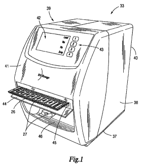
100891 There is shown in FIG. 1, a delivery module 33 including a preferably
plastic, box-like
housing adapted to rest upon a surface and having a base 37 which supports
top, side 38, 39,
front 41 and rear 40 panels. The front panel 41 features an electronic display
42 on which
alphanumeric information and instructions related to a particular unit dose
are communicated to
the patient. In an embodiment, the electronic display 42 may also display a
picture of a
therapeutic product prior to, during and/or after dispensing such product. The
electronic display
42 may comprise, for example, a liquid crystal display, digital display or
other suitable
communication means. Portions of the front panel 41 are also configured with
an audible alarm
to alert the patient of the need to take a prescribed unit dose package 27. To
allow for patient
CHICAGO/# 1667512.1
CA 02693893 2010-01-15
WO 2009/012371 PCT/US2008/070305
input, the front panel 41 of the housing includes control keys 43 that
function as confirmation
keys in accordance with the audible alarm and electronic display 42 to enable
the patient to take
delivery of a prescribed dosage. An audio speaker and remote communication
interface may
optionally be incorporated within the housing for providing additional
instructions to or
receiving feedback information from the patient. An alternative embodiment of
the invention
includes temperature control means (e.g. refrigeration means) for regulating
the temperature of
the module 33 as may be required for certain medications. A power outlet
allows the delivery
module 33 to be connected to an external AC power source.
[0090] In an embodiment, the delivery module 33 may include a battery backup
that powers the
unit when external power is lost. Such battery backup may be charged using
external power
during non-nal operation, as known in the art. The delivery module 33 may
automatically eject
one or more medication carriers 26 stored within the delivery module when
external power is not
present and the battery level falls below a pre-defined threshold, as
described in further detail
below.
[0091] In a further embodiment, the invention includes a wireless
communication device worn
by the patient which is communicatively linked with the delivery module 33 to
provide an
additional alert to some patients. The wireless communication device may be,
for example, a
wrist watch, pager or pendant. Alternatively, a patient may be alerted via
telephone or email.
[0092] Access to the medication carriers 26 and internal hardware of the
delivery module 33 is
provided when the side panels 38, 39 are unlocked and open. In order to
prevent unwanted
access to the medication carriers 26, the side panels 38, 39 may remain locked
at all times unless
actuated by the controller in response to a command originating from the
control center or
26
CHICAGO/#1667512.1
CA 02693893 2010-01-15
WO 2009/012371 PCT/US2008/070305
clinical facility. Alternatively, access to the interior of the module 33 can
be granted to a patient,
designated caregiver or other authorized personnel by way of a smart card or
security access
password. The smart card or restrictive password must typically be entered
prior to interacting
with the delivery module in instances where one or more unit dose packages
have been
quarantined or recalled. In a further embodiment, the delivery module 33
includes speech
recognition means for receiving and interpreting prescribed verbal commands
made by the
patient or other authorized personnel.
[0093] In a manner well known in the art, each constituent of the delivery
module 33 is
operatively coupled to and controlled by the controller, through control
signals, in response to a
command instruction set received from a computer server based at the control
center 101. The
controller transmits verification to the control center 101 that information
has been received and
instructions have been carried out. The controller is programmed to activate
the dosage "drop"
function at appropriate times based on information remotely communicated from
the control
center 101. In particular, the controller activates the alarm, key pad 43,
wireless communication
circuitry, electronic display 42, sensors, scanners 92, 98, actuators 60, 72,
91, motors 54, 73, 80,
87 and other electronic devices.
100941 The controller can be one of several standard microprocessor-based
controllers having
standard type actuator or servo drive interfaces and detector inputs, or other
suitable circuitry
capable of employing software control, hardware control or a combination
thereof. Internal
memory is used to store, for example, dosage delivery instructions and logic
programs. In an
embodiment, and as described in further detail below, the interrrnal memory
may store medication
administration information for one or more medications, such as medications to
be administered
27
CHICAGO/{t 1667512.1
CA 02693893 2010-01-15
WO 2009/012371 PCT/US2008/070305
to a patient on an "as needed" basis or some other basis. The management and
administration of
such medications may be controlled by one or more of the logic programs stored
in the internal
memory. The controller may be used to perform the programs stored in internal
memory. Control
signals travel by way of a distribution panel to and from the various
components configured
within the delivery module 33. FIGS. 16-20 further illustrate the controller's
mode of
communicating with electronic architecture of the delivery module 33.
(0095] In an embodiment, the memory may store a user-defined description for
each medication
stored in the delivery module 33. The user-defined description may include a
commonly used or
slang name for the product that enables the user to more easily identify the
dose that is being
administered. For example, the user may refer to particular medications as
"water pill," "sleeping
pill," etc. and not by the product name. Accordingly, by using the user-
defined description, the
user may have more complete knowledge of the medications that are being taken.
[0096] In the exemplary embodiment shown in FIG. 6, a storage elevator 47 is
designed to
accommodate up to ten medication carriers 26, each containing a thirty day
supply of different
therapeutic agents in a variety of dosage forms and strengths. The delivery
module 33 is
therefore capable of storing approximately three hundred unit dose and unit-of-
issue packages 27
of medication. As shown in FIG. 14, each carrier 26 may include different
dosage strengths for a
single medication. This allows different dosage strengths to be combined to
obtain a desired
dosage amount. While the instant design is appropriate for use in a home,
assisted living facility,
long-term care facility or other residential setting, a delivery module 33
having a storage elevator
47 that can accommodate, for example, up to three hundred medication carriers
26 is preferable
for use in an institutional environment (e.g. a correctional institution). The
storage elevator 47
28
C H ICAGO/# 1667512.1
CA 02693893 2010-01-15
WO 2009/012371 PCT/US2008/070305
may store medication carriers 26 in any orientation, such as horizontally
and/or vertically, within
the scope of the present disclosure.
[0097) The location of each unit dose package 27 and medication carrier 26
within the delivery
module 33 is determined, in part, through the use of electronic identifier
codes 29, 31 or other
inventory code systems. The electronic codes 29, 31 imprinted on the
medication carriers 26 and
individual unit dose packages 27 are scanned by an electronic code reader 98
as each medication
carrier 26 is loaded into the delivery module 33. The encoded information is
transmitted to the
control center 101 computer server, where it is associated with a stored
database record by the
control software 35. This information allows a healthcare practitioner to
actively treat a patient
remotely located from a clinical facility.
100981 The healthcare practitioner, by way of the menu-driven user interface
100, simply
retrieves and reviews the inventory of unit dose and unit-of-issue packages 27
stored within the
patient's delivery module 33 and selects an appropriate dosage within the
parameters prescribed
for the patient. Upon receipt of a command signal from the control center 101
computer server,
the patient's delivery module 33 expels the selected dosage based on the
electronic identifiers 29,
31 and position coordinates of such dosage within the delivery module 33.
[0099] As shown in FIG. 6, the storage elevator 47 includes a cavity which is
partitioned into
multiple storage bays 48 disposed on separate levels of the elevator 47. Each
storage bay 48 has
a horizontal opening of a sufficient size to provide the range of motion
necessary to allow a
transport carriage 49 stored within the bay 48 to be moved in both forward and
rearward
directions. The transport carriage 49 includes an open-ended frame that
defines a fluting 50
disposed along the length of said frame, such that peripheral edges of the
medication carrier 26
29
CHICAGO/#1667512.1
CA 02693893 2010-01-15
WO 2009/012371 PCT/US2008/070305
can be readily fitted within said fluting 50. The carriage 49 is supported by
a horizontal railing
51 which extends along the interior surfaces of the storage bay 48. Ends of
the railing 51
terminate about a concentric shaft 52 that is generally flush with the opening
of the bay 48.
1001001 Rotatable spur gears or sprocket drives 53 are mounted at both ends of
the shaft
52 so as to come into contact with and suitably engage corresponding
stationary gears that
protrude from peripheral edges of the carriage 49 for effecting forward and
rearward movement
of the transport carriage 49. The spur gears 53 are rotated by a drive motor
(e.g. a servo motor)
54 in a controlled fashion, in response to signals from the controller. While
a gear assembly is
described herein for moving the transport carriage 49 in both forward and
rearward directions, it
should be understood that any suitable drive assembly may be employed.
Location markers are
provided along an outer edge of the transport carriage, which indicate the
exact horizontal
position ("y-axis") of the carriage 49 and integral medication carrier 26.
This information is
monitored by the controller through a feedback loop arrangement. Once the
controller
determines that an appropriate number of markers have been scanned by an
electronic code
reader 98 mounted within the storage elevator, the drive motor 54 is
disengaged. The transport
carriage 49 nonnally resides within the storage bay 48 (the "home position"
99) until a
prescribed dosage is to be taken or a medication carrier 26 is to be
replenished.
[00101] As discussed above, the transport carriage 49 is adapted for
horizontal (x-axis)
movement between rear and forward positions (FIGS. 9 and 10). Upon receiving a
"dose
delivery" signal from the controller, the drive motor 54 rotates spur gears 53
of the desired
storage bay 48, such that the carriage 49 and integral medication carrier 26
are moved in a
forward direction, sufficiently to clear the opening of the storage bay 48,
and achieve a "delivery
C H ICAGO/# 1667512.1
CA 02693893 2010-01-15
WO 2009/012371 PCT/US2008/070305
ready" position in proximity to a vertically disposed plunger 93. Likewise,
during a carrier 26
unloading operation, the drive motor 54 advances the transport carriage 49 to
a forward position
in which a portion of the carriage extends beyond the opening of the storage
bay 48. At such
point, additional forward movement of the carriage 49 is accomplished through
the action of a
friction drive assembly 56. Sensors are located to monitor the movement and
alignment of the
transport carriage 49 as it is moved in both forward and rearward directions.
1001021 Referring now to FIG. 1, a handle equipped loading door 44 and
insertion/retrieval slot 45 are provided in the front panel 41 of the housing.
When the door 44 is
open, the slot 45 is accessible for inserting a medication carrier 26 filled
with unit dose packages
27 of prescription or non-prescription medications and supplies. Adjoining the
interior surface of
the front panel 41 is a loading area with components for receiving the
medication carrier 26 into
the delivery module 33. Each of these components will be described in detail
below in reference
to FIGS. 7-10 and 17.
[00103] A sensor is located in the loading area to detect the presence of an
incoming
medication carrier 26. The sensor is, for example, a micro-switch, optical eye
or other electrical
contact suitable for monitoring the orientation of the medication carrier 26
relative to a limit
switch embedded within the loading area. When the sensor detects that the
medication carrier 26
has been fully inserted, through activation of the limit switch, a friction
drive assembly 56 is
immediately actuated.
[00104] A pair of parallel guide rails 57, 58 are horizontally mounted to the
side panels
38, 39 to enable the transport carriage 49 and an incoming medication carrier
26 to be properly
aligned and dispatched through the loading area of the housing to the storage
elevator 47. One
31
CHICAGO/#1667512.1
CA 02693893 2010-01-15
WO 2009/012371 PCT/US2008/070305
end of each of the guide rails 57, 58 abuts the interior surface of the front
panel 41 such that the
guide rails 57, 58 at that point intersect the insertion/retrieval slot 45
configured in the front
panel. The guide rails 57, 58 extend through the midsection of the housing and
terminate in front
of the storage elevator 47.
[00105] Latch apparatus 59 is configured to allow the incoming medication
carrier 26 to
be secured onto the transport carriage 49 and dispatched through the loading
area. The latch
apparatus is 59 operatively coupled to a solenoid 60, or other
electromechanical actuator, which
is mounted to a side panel 38 of the housing by a bracket and screws, or
similar hardware. A
retractable spring 61 and plunger 62 are provided at the upper end of the
solenoid 60, the plunger
62 including a groove 64 in a top portion thereof which supports one end of
the latch apparatus
59. An opposite end of the latch apparatus 59 features an angle 63 that abuts
peripheral edges of
the guide rail 57 and vertically protrudes above the guide rail 57 so as to
obstruct the loading
pathway.
[001061 Upon actuation by the controller, the solenoid 60 biases the spring 61
and plunger
62 downward. This, in turn, lowers the latch apparatus 59 to a position below
the guide rail 57 so
that the transport carriage 49 can be positioned on the exposed, upper surface
of the guide rails
57, 58 for movement beyond the storage bay 48 to a "prime" position, planate
with the front
panel 41 of the housing. The solenoid 60 retains the latch apparatus 59 in
this suppressed
orientation while the medication carrier 26 is loaded into the delivery module
33, through the
insertion/retrieval slot 45. As the incoming medication carrier 26 enters the
loading area, the
carrier's 26 peripheral edges automatically slot into the carriage fluting 50
so as to form an
integral unit therewith for transport to a storage bay 48. At such time, the
latch apparatus 59 is
32
CHICAGO/# 1667512.1
CA 02693893 2010-01-15
WO 2009/012371 PCT/US2008/070305
returned to its initial, indexed position against the peripheral edges of the
guide rail 57 under the
force of the solenoid 60.
1001071 A short distance above the guide rails 57, 58 is a swivel bracket 65
which is
mounted to and pivots about a horizontal rod 66 attached to the side panels
38, 39 of the housing.
The bracket 65 is configured for mounting a friction drive assembly 56 that
controls movement
of the transport carriage 49 and medication carrier 26 through the loading
area. The bracket 65
forms an arch about its anterior, peripheral edges which features opposing
vertical flanges 67,
68. The flanges permit a drive shaft 69 and a pair of drive wheels 70, 71,
spaced substantially
equally apart, to be conveniently attached to the bracket 65. It should be
noted that the drive
wheels 70, 71 are preferably made of rubber, soft, compressible polyurethane
foam or other
material that is capable of gripping a medication carrier 26 containing
individual unit dose
packages 27 without breaking or damaging the medication contained therein.
Vertically
suspended from an opening in a top surface of the bracket 65, directly above a
guide rail 57, is an
electromechanical actuator 72 which distends to mate with and exert pressure
on an upper
surface of the medication carrier 26, in response to a control signal. This
action causes the
bracket 65 to pivot downwardly, so as to assume an angled position and lower
the drive wheels
70, 71 onto the upper surface of the transport carriage 49.
[00108] A drive motor 73 such as, for example, a servo motor, is secured to
the swivel
bracket 65 and operatively coupled to a pulley system 74. The pulley 74 is
mounted in
perpendicular relation to the drive shaft 69 and is moveable relative thereto
by means of the
motor 73. Upon actuation, the motor 73 rotates the pulley 74, which in turn,
rotates the drive
wheels 70, 71. The rotary motion of the drive wheels 70, 71 directs the
medication carrier 26 and
33
CHICAGO/# 1667512. I
CA 02693893 2010-01-15
WO 2009/012371 PCT/US2008/070305
transport carriage 49 inwardly, toward the storage elevator 47. Once the
transport carriage 49 and
carrier 26 reach the opening of the vacant storage bay 48, the carriage's 49
protruding gear
elements engage rotatable spur gears or sprocket drives 53 mounted about the
opening of the
storage bay 48, moving the carriage 49 and medication carrier 26 toward the
rear of the storage
bay 48. When the sensor detects that the medication carrier 26 and transport
carriage 49 have
arrived at their home position 99, the controller disengages the motor 73 and
drive wheels 70, 71.
[00109] Referring now to FIGS. 3 and 11, the storage elevator 47 is operably
connected to
an elevator bracket 77 which moves the elevator 47 from a rest position, in
the lower section of
the housing, to an operative position, adjacent the delivery area, along a
vertical ("z") axis.
Vertical movement is achieved by means of a linear motion assembly 78 such as
a gear belt and
lead screw 81, pulley, or other standard drive component capable of converting
rotary motion
from a drive motor to linear motion. In the exemplary embodiment, a timing
belt and lead screw
81 are rotated by a stepper motor 80 mounted to the base 37 of the housing.
The motor 80 is
actuated in accordance with electrical signals received from the controller
(FIG. 18). The base 37
also accommodates the controller and a battery pack (not shown).
1001101 The elevator bracket 77 generally spans the length of the delivery
module 33 so as
to allow the storage elevator 47 to be raised and lowered to a desired level
for accessing a
medication carrier 26 stored within a particular storage bay 48. The elevator
bracket 77 includes
a channel housing 82 having a hollow portion in the center thereof and
corresponding openings
in upper and lower surfaces through which the lead screw 81 and one or more
guide rods 83, 84
vertically extend. In general, the channel housing 82 serves as a frame for
supporting the various
components of the elevator bracket 77 and imparting stability to the guide
rods 83, 84, or other
34
CHICAGO/# 1667512.1
CA 02693893 2010-01-15
WO 2009/012371 PCT/US2008/070305
suitable vertical shaft, such as, for example, an adjustable slide and block
assembly. The channel
housing 82 is vertically mounted to the base 37 of the delivery module 33,
adjacent the rear panel
40, and is secured in place by bolts, casters or other suitable hardware.
[00111] Also featured in the hollow portion of the channel housing 82 are
upper and lower
cross members 102, 26, mounted in horizontal relation to the guide rods 83, 84
and lead screw
81, and interpolated by through holes in which the guide rods 83, 84 and lead
screw 81,
respectively, are slidably disposed. The cross members 102, 26 move along the
perpendicular
guide rods 83, 84 by operation of the motor 80 and lead screw assembly 81.
This configuration
permits a carrier plate 85 attached to the anterior surface of the cross
members 102, 26 to be
raised and lowered, in accordance with the direction of motion of the lead
screw 81. The carrier
plate 85 generally extends across the width of the housing and serves as a
platform for
attachment and support of the storage elevator 47. The storage elevator 47
includes a metal
protrusion that projects outwardly from the rear wall of the elevator. The
protrusion is suitably
shaped to conform to a corresponding depression in the carrier plate 85 so
that the carrier plate
and storage elevator 47 can be conveniently and securely attached thereby.
[00112] The position of the storage elevator 47 within the housing is
determined by means
of an encoder located in the drive motor 80 which relays positional
information to the controller
in the form of electrical pulses as the motor 80 rotates (FIG. 11). Once the
appropriate number of
pulses is emitted by the encoder, signaling that the storage elevator 47 has
attained the correct
position for accessing a desired medication carrier 26, the controller
disengages the motor 80. In
this manner, the storage elevator 47 can be raised or lowered to an
appropriate level within the
housing.
CHICAGO/# 1667512.1
CA 02693893 2010-01-15
WO 2009/012371 PCT/US2008/070305
1001131 Referring now to FIG. 12, an ejector assembly 55 is provided for
releasing a
prescribed unit dose/unit-of-issue therapy 27 to a patient at a predetermined
time, in accordance
with a drop command originating from the clinical software 32. The ejector
assembly 55 is
mounted on and moves along a horizontal slide ("x-axis") 86 which extends
across the width of
the delivery module 33, between the storage elevator 47 and loading area.
During dose delivery,
the ejector assembly 55 is moved from a rest position 88 into an operative
position 89 suitable
for achieving contact with a desired unit dose package 27. Identification of
the correct unit dose
package 27 is determined by the control software 35, which correlates each
instruction from a
healthcare practitioner with a specific unit dose package 27. The ejector
assembly 55 includes a
sensor, electronic code scanner 92, electromechanical actuator 91, and a
plunger 93, wherein
each component is vertically positioned within and supported by a receptacle
90 that is slidably
attached to the horizontal slide 86. The ejector assembly 55 is moved in the x-
direction by means
of a motor 87 operatively coupled to and under the control of the controller.
The
electromechanical drives on the ejector/reader (y-axis), elevator (z-axis),
and carriage (x-axis)
are specifically designed for non-slip reliability.
1001141 A sensor (not shown), such as an optical sensor, is located to sense
the movement
and alignment of the ejector assembly 55 as it is moved into an operative
position 89 in
proximity to the desired unit dose package 27. The sensor ensures that such
operative position 89
corresponds to the designated position coordinates of the selected therapy.
This is accomplished
by means of a feedback loop arrangement with the controller.
[00115] An electronic code scanner 92, such as a bar code reader, optical
recognition
reader, radio frequency identification tag reader or other similar device, is
operatively coupled to
36
CHICAGO/# 1667512.1
CA 02693893 2010-01-15
WO 2009/012371 PCT/US2008/070305
and suspended from a lower end of the actuator 91 so that the head of the
scanner is positioned in
proximity to upwardly facing electronic identifier codes 29, 31 imprinted on
the medication
carrier 26 and seal of the desired unit dose package 27. The scanner 92
detects removal of a unit
dose package 27 from a stall 28 of the medication carrier 26, through
interruption of a light beam
emitted therefrom, and thereafter, transmits a signal to the controller
confirming such removal.
An electronic imaging device (e.g. a camera) may also be incorporated to
provide visual
feedback that the desired medication is suitably discharged from the
medication carrier 26.
[00116] A plunger 93, having an elongated shaft 94, is mounted for vertical
movement
between raised and lowered positions by means of a linear actuator 91 attached
to the shaft 94
thereof. The lowerlnost end of the shaft 94 terminates in a flat, compacting
edge 95 which is
suspended directly above the stall 28 of the medication carrier 26 containing
the desired unit
dose package 27. Upon receipt of a control signal, the actuator 91 forces the
plunger 93
downward such that the plunger 93 achieves contact with the encoded surface of
the unit dose
package 27, pushing the package 27 through the opening of the stall 28.
Alternately, the actuator
91 forces the plunger 93 downward such that the plunger 93 achieves contact
with the non-
encoded surface of the unit dose package 27, pushing a therapeutic product
contained therein out
of the unit dose package 27.
[00117] A ramp 96 or chute is mounted to the side panels 38, 39 of the housing
beneath
the ejector assembly 55. The ramp 96 is generally a flat surface which extends
across the width
of the delivery module 33 and slopes downwardly so as to channel the ejected
unit dose package
27 or therapeutic product to a rotatable guard 971ocated at the end of the
ramp 96. The guard 97
is used for temporarily retaining an ejected unit dose package 27 until each
of the medications
37
CHICAGO/#1667512.1
CA 02693893 2010-01-15
WO 2009/012371 PCT/US2008/070305
within the patient's regimen is expelled. Once each of the prescribed
medications is expelled, the
guard 97 is rotated away from its initial position by a servo motor, releasing
the ejected unit dose
packages 27 or therapeutic products into a receiving area 46 for collection by
the patient.
1001181 The receiving area 46 is an open section configured in the front panel
41 of the
housing where the medication is retrieved by a patient for consumption.
Medication related
information, such as the type, quantity and dosage of the discharged unit dose
packages 27 or
therapeutic products, appears on the electronic display 42. Alternatively, or
in addition, a
healthcare practitioner may communicate directly with the patient by providing
instructions,
additional information, or receiving feedback from the patient through the
remote
communication interface and display 42, keypad 43 or speaker.
1001191 FIGS. 23 and 24 are flowcharts of the functional steps employed in the
non-
sequential delivery sequence of the present invention to deliver a desired
therapeutic dosage to a
patient as part of the same prescription period.
1001201 As mentioned above, a significant aspect of the instant invention is
that it enables
a physician, pharmacist, nurse or other healthcare practitioner remotely
located from a patient to
deliver any of the unit dose and unit-of-issue packages 27 (or therapeutic
products contained
therein) stored within the delivery module 33 to the patient, in non-
consecutive order, without
being limited by a predetermined sequence. This unique delivery scheme allows
the healthcare
practitioner to instantaneously modify, queue, change, or discontinue a
prescribed dosage in
response to fluid medical conditions. Therefore, the precise location and
contents of each unit
dose package 27 contained within the delivery module 33 must be known at all
times, both prior
38
CHICAGO/#1667512.1
CA 02693893 2010-01-15
WO 2009/012371 PCT/US2008/070305
to and during the dose delivery process. The present system uses a feedback
loop arrangement to
manage this flow of data.
[00121] In operation, a healthcare practitioner enters patient prescription
information and
dosage schedules using the Fulfillment, Adjustment and Compliance Tracking
System
(FACT"I'"'), or other clinical software application 32 (FIG. 22). Patient
information is accessed by
way of the software's user interface 100, which features a complement of menu-
driven
worksheets that appear on the practitioner's computer monitor. FIG. 29 is a
worksheet showing a
monthly therapy schedule for a patient, which is stored in memory. Other
examples of
worksheets which the health care provider uses to interact with the clinical
software 32 are
provided in FIGS. 27-28 and 30-31. All patient information, which includes,
for example,
prescription information, medication dosing schedules, dosage delivery
criteria such as drug-
drug interactions and food-drug interactions, and a history of dosage delivery
results, is stored
within the clinical software database 32. The clinical software database 32
utilizes the clinical
facility's network security 34 policies and procedures to authenticate users
and network access to
patient information, in conformity with the Health Insurance Portability
Accountability Act.
1001221 Just before a scheduled dosing time, the clinical software 32
transmits an
encrypted signal to the control software 32 operating on a server located at
the control center 101
to initiate delivery of a particular medication for a particular patient. The
signal contains a
command instruction set representing a prescribed medication regimen and
dosing schedule for
the patient, as well as a randomly generated Unit Identification Number (UIN)
assigned to that
patient's delivery module 33. Neither the patient's name nor any information
identifying the
patient is transmitted beyond the medical facility's firewall 34. Accordingly,
only the clinical
39
CHICAGO/# 1667512.1
CA 02693893 2010-01-15
WO 2009/012371 PCT/US2008/070305
software 32 can correlate the prescribed regimen and dosing schedule, or
delivery module 33, to
the patient.
[00123] Following transmission, the signal is interpreted and authenticated by
a control
center 101 computer server. Utilizing the UIN, the server's control software
35 links each
command instruction embedded within the signal to a specific delivery module
33. Next, the
control software 35 utilizes a look up routine to correlate the instruction to
a specific medication
carrier 26 containing the desired unit dose package 27. This information,
based on the encoded
identifiers 29, 31 assigned to the inedication carrier 26 and unit dose
packages 27, is stored in the
control software 35 database. The control software 35 ascertains the specific
location within the
delivery module 33 of the unit dose package 27 or therapeutic product that is
to be delivered to
the patient in accordance with the programmed dosing schedule.
1001241 The control software 35 database specifies the vertical location (z-
coordinate) of
the medication carrier 26 as well as the row and column positions of the stall
28 containing such
dose (y- and x-coordinates, respectively). In addition, the control software
35 database provides
specific dose ejection parameters based on the internal configuration of the
medication carrier 26
and the type of medication contained therein. This is accomplished using the
stored electronic
data which is communicated to the control center 101 computer server as the
medication carriers
26 are loaded into the delivery module 33.
[001251 In the next step, the control software 35 reformats the signal into a
proprietary
protocol which includes a randomly generated communication's token and
instructions for the
delivery module 33 to drop the desired medication based on the x-, y- and z-
coordinates of such
medication. The instructions ensure that the correct medication, in an
appropriate dosage form
CH ICAGO/# 1667512.1
CA 02693893 2010-01-15
WO 2009/012371 PCT/US2008/070305
and amount, is delivered to the patient. The server transmits the reformatted
signal to the
controller located within the patient's delivery module 33 via radio
frequency, or other suitable
link. The controller interprets the command sent from the control center 101
server and sends
confirmation thereto. This confirmation contains the communications token
required for
verification by the control server 101. In response, the control server 101
transmits a
reconfirmation signal to the delivery module 33, authorizing the controller to
drop the prescribed
medication.
1001261 The module's 33 dose delivery sequence is activated upon receipt of
the
reconfirmation signal. The controller alerts the patient of the need to take
the prescribed unit
dose therapy 27 by way of the alarm, display 42 or other suitable visual,
audible or other means.
In an embodiment, a speaker may be used to provide an alert in a language
known to the user.
The controller concurrently establishes a window of time, relative to the
alerting signal, during
which the patient can input a delivery signal by, for example, depressing the
drop key on the
control panel 43. If the aural and visual signaling is ignored by the patient,
the signaling will
repeat every minute or more up to a programmed interval. The duration of the
time window is set
by the entered program or by a default value.
[001271 If the patient depresses the drop key 43 during the programmed time
window, the
controller, in cooperation with the drive motor 80, raises the storage
elevator 47 to the correct
vertical position (FIGS. 11 and 18) for accessing the storage bay 48
containing the unit dose
package 27 or unit dose to be delivered, in accordance with z-coordinate
specified in the
command instruction set. The position of the storage elevator 47 within the
housing is
determined by means of the motor-based encoder which relays positional
information to the
41
CHICAGO/# 1667512.1
CA 02693893 2010-01-15
WO 2009/012371 PCT/US2008/070305
controller, in the form of electrical pulses, as the motor 80 rotates. Once
the appropriate number
of pulses is emitted, signaling that the storage elevator 47 has attained the
correct position, the
controller disengages the drive motor 80.
[00128] When the storage elevator 47 reaches the correct level for accessing
the
designated storage bay 48, the controller actuates the servo motor and pulley
assembly 54 which
controls horizontal movement in the y-direction (FIG. 19) so as to move a
transport carriage 49
and integral medication carrier 26 housed within the storage bay 48 forward,
away from the
home position 99. An electronic code scanner 98 located within the storage
elevator 47 reads
location markers disposed along the outer edge of the carriage 49, which
indicate the position of
the carriage 49 and medication carrier 26 as they are advanced. This
positional information is
monitored by the controller through a feedback loop arrangement. Once the
controller
determines that an appropriate number of markers have been scanned, in
accordance with the y-
coordinate instruction received from the control server, the motor and pulley
assembly 54 are
disengaged. As the transport carriage 49 and carrier 26 are moved into proper
position, the
scanner 98 also reads an encoded identifier label 29 affixed to the upwardly
oriented surface of
the medication carrier 26, which contains the x-coordinate operational
parameters.
[00129] At this point, the transport carriage 49 and medication carrier 26
have sufficiently
cleared the opening of the storage elevator 47 such that the desired unit dose
package 27 or unit
dose is positioned beneath the horizontal slide 86 of the ejector assembly 55.
A control signal
(FIGS. 16 and 20) is sent to the motor 87 responsible for movement about the x-
axis so as to
advance the slide-mounted receptacle 90 from a rest position 88 into an
operative position 89
above the medication that is to be delivered. In this delivery ready position,
the compacting edge
42
CH ICAGO/# 1667512.1
CA 02693893 2010-01-15
WO 2009/012371 PCT/US2008/070305
95 of the plunger 93 is suspended directly above the upwardly oriented,
encoded 31 surface of
the unit dose package 27. In an alternate embodiment, the compacting edge 95
of the ejector
assembly or plunger 93 is suspended above the non-encoded surface of the unit
dose package 27
when a unit dose is to be removed from the unit dose package. Other
embodiments are possible
within the scope of this disclosure.
[00130] In this orientation, the code scanner 92 suspended from the lower end
of the
actuator 91 is also positioned in proximity to the electronic identifier code
31 on the seal of the
unit dose package 27. In instances where supplementary confirmation of
delivery is desired, the
scanner 92 reads the identifier code 31 and transmits verification to the
controller that the
selected dosage is the correct one, as a redundant check. The control software
35 layer links each
command to a specific medication carrier 26 and unit dose package 27, the
identification of
which is scanned and verified at the time of loading the delivery module 33.
[00131] In the next step, a control signal is sent to the actuator 91
connected to the shaft
94 of the plunger 93. As this occurs, the shaft 94 is biased downward, whereby
the compacting
edge 95 contacts the encoded 31 surface of the unit dose package 27. This
action causes the
retaining means 30 of the affected stall 28 to release the unit dose package
27 contained therein.
The ejected package 27 drops onto the ramp 96 situated beneath the ejector
assembly 55, and
thereafter slides into the rotatable guard 97 located at the bottom of the
ramp 96. The guard 97
temporarily retains the ejected medication until each of the medications
within the patient's
regimen is expelled. In an alternate embodiment, the compacting edge 95 may
contact the non-
encoded surface of the unit dose package 27 causing the surface to compress
and push the
therapeutic product (or unit dose) through the encoded surface 31 of the unit
dose package. In an
43
CH ICAGO/# 1667512.1
CA 02693893 2010-01-15
WO 2009/012371 PCT/US2008/070305
embodiment, the unit dose package 27 may be retained within the retaining
means 30 of the
affected stall 28 when the therapeutic product is released. The therapeutic
product may then
drop onto the ramp 96 situated beneath the ejector assembly 95, and slide into
the rotatable guard
97, which temporarily retains the ejected medication until each medication in
the patient's
regimen is expelled.
[00132] When the electronic code scanner 92 detects removal of the unit dose
package 27
out of the medication carrier 26 or the removal of the therapeutic product
from the unit dose
package 27, a signal is sent to the controller, verifying that the prescribed
dose is suitably
removed from the carrier 26. In instances where visual identification is
desirable, an electronic
imaging device may be used to independently verify that the desired medication
is suitably
discharged from the carrier 26.
[00133] If additional unit dose packages 27 or therapeutic products are
scheduled to be
expelled from the same medication carrier 26, e.g. in instances where multiple
dosage strengths
of the same medication are combined to obtain a correct dosage amount, the
carrier 26 is again
advanced in the y-direction, while the ejector assembly 55 is moved into the
appropriate x-
position. Once all of the prescribed medications have been ejected from the
medication carrier
26, the transport carriage 49 and carrier 26 return to their home position 99
within the storage
bay 48.
1001341 If a prescribed unit dose package 27 or therapeutic product is
contained in a
different medication carrier 26, the storage elevator 47 is raised or lowered
to the appropriate
level, in accordance with the z-coordinate specified in the command
instruction set. Thereafter,
the transport carriage 49 and medication carrier 26 are moved forwardly, into
the correct y-
44
CHICAGO/# 1667512.1
CA 02693893 2010-01-15
WO 2009/012371 PCT/US2008/070305
position, while the receptacle 90 of the ejector assembly 55 is moved in the x-
direction. When
the medication carrier 26 is in proper position, the plunger 93 pushes the
dose 27 out of the
carrier 26, causing the ejected dose 27 to fall onto the ramp 96. Alternately,
the plunger 93 may
release the therapeutic product from the unit dose package 27 to fall onto the
ramp 96. This
sequence is repeated for each of the medications within the patient's regimen,
in accordance with
the instructions received from the control center 101 computer server. It
should be understood
that all of the medications for a particular dosage period are ejected in
rapid succession, typically
requiring less than ten seconds to eject each medication.
[00135] Once all the medications for the scheduled dosage time are expelled
from their
respective medication carriers 26, the controller activates the audible alarm,
electronic display 42
or other suitable alert mechanism to notify the patient that medication is
ready to be taken.
Simultaneously, a control signal actuates the servo motor that is operatively
coupled to the
rotatable guard 97 at the base of the ramp 96. As the guard 97 rotates, the
ejected, fully sealed
unit dose packages 27 or therapeutic products fall into the receiving area 46
for collection by the
patient. At the same time, the electronic display 42 presents a description of
the medical products
placed into the receiving area 46, which may include, for example, the type,
quantity and dosage
of the delivered medical products.
[00136] In order to monitor compliance as well as maintain a complete audit
trail of the
patient's interaction with the delivery module 33, the module automatically
transmits a signal to
the control center 101 computer server, via radio frequency, or other
communication link 36,
once the dosage is discharged. The signal confirms that the prescribed dosage
has been delivered
to the patient within the scheduled dosing period. The transmission is date
and time stamped in
CHICAGO/#! 1667512.1
CA 02693893 2010-01-15
WO 2009/012371 PCT/US2008/070305
order to provide an accurate record of the transaction. The control software
35, which operates
on the control center 101 server, receives and decodes the signal. Once the
signal is
authenticated, the control software 35 systematically updates the status of
each unit dose package
27 or therapeutic product delivered during the scheduled dosing period. The
updated usage
information is stored in the control software 35 database so as to provide
precise inventory
control and flawless delivery of the diverse medical products contained within
the delivery
module 33. The dosage administration transaction record is also stored in the
control software 35
database, then formatted into an XML message stream and sent to the clinical
software layer 32
in the succeeding polling cycle, using an encrypted Secure Socket Layer 25.
1001371 As described in further detail below, a user may enter one or more
dates and/or
times corresponding to a period of time in which the user will not have access
to the delivery
module 33, such as if the user is going on vacation, to work, to school,
shopping or the like. The
delivery module 33 may determine the doses to be administered based on the
entered dates
and/or times and may eject such doses to the user. The user may enter the one
or more dates
and/or times via an input device, such as a key pad 43, and may display
information pertaining to
when to take each dose to the user via a display device, such as 42.
1001381 Every few minutes, the clinical software 32 checks for status updates
sent to the
clinical facility's data server. When the clinical software 32 receives the
transaction record, the
software 32 stores the information in the database which houses the patient's
therapeutic regimen
and dose delivery instructions entered by the healthcare practitioner. The
transaction record
provides, for example, an updated, complete inventory of the unit dose
packages 27 contained
within the patient's delivery module 33 as well as the date and time that the
prescribed dosage
46
CHICAGO/# 1667512.1
CA 02693893 2010-01-15
WO 2009/012371 PCT/US2008/070305
was received by the patient. This information is directly provided to one or
more computer
stations 100 within the clinical facility, enabling an authorized healthcare
practitioner to review
the patient's dosage delivery results in real time. Once the dosage
confirmation message is
received from the control center server, signifying that the prescribed dosage
has been delivered
to a patient, the clinical software 32 initializes a routine to remove that
particular dosage delivery
event from the pending list.
1001391 If the patient fails to respond to the alann generated by the delivery
module 33 at
a scheduled dosing time, e.g., by pressing the drop key 43 of the delivery
module 33 at the end of
the programmed time window, a routine is initialized which may include a call
to the patient or a
call to the patient's care provider, doctor, pharmacist or other designated
individual. The delivery
module 33 automatically transmits an alert to the control center 101 server,
via radio frequency
or other suitable communications link 36. Immediately thereafter, notification
of the missed
dosage is transmitted to the clinical facility's data server using the secure
encryption method 25
as described above.
[00140] A further embodiment uses, for example, two time windows during which
the
patient may input the delivery signal, e.g., depress the drop key 43. In the
first time window, the
delivery module 33 generates an audible, visual or other alann at a first
intensity. If that first
time window ends and the patient has not yet entered the delivery signal the
module 33 increases
the alarm level. The increased alarm level is continuous or, alternatively,
steadily increases until
the end of the second time window. Notification of the non-compliance action
is transmitted to
the control center 101 servers if the patient, at the end of the second time
window, has still not
responded to the alann.
47
CHICAGO/#1667512.1
CA 02693893 2010-01-15
WO 2009/012371 PCT/US2008/070305
[001411 Delivery of the scheduled dosage does not occur unless the patient
actuates the
drop key 43 within the designated time interval. In this way, the present
invention ensures that
the patient receives the exact dose prescribed at the correct dosing time.
This feature improves
adherence and protects the patient from adverse drug interactions which may
result from taking
multiple doses of medication at unscheduled dosing times.
1001421 Patient dosage administration results are routed to and received by
the clinical
facility in real time. The clinical software 32 automatically alerts the
healthcare practitioner of
the non-compliance action by generating an alert message which is displayed on
the
practitioner's computer monitor (user interface 100). The practitioner can
then take timely action
by directly contacting the patient and/or directing an appropriate command
back to the delivery
module 33, or as otherwise described below.
[00143] After reviewing the notification of non-compliance, the patient's
physician,
pharmacist or other licensed healthcare practitioner retrieves and evaluates
the patient's treatment
regimen, which is stored within the clinical software 32 database and is
accessed by way of the
user interface 100. This information includes, but is not limited to,
prescription information such
as the name, type (brand or generic), potency strength and dosage form of a
prescribed medical
product, dosing schedules, dosage administration criteria such as drug-drug
interactions and
drug-food interactions, and the next pending dosage delivery event. The
healthcare practitioner
then determines whether the patient's medication regimen, dosing schedule, or
both, should be
modified to accommodate the missed dosage by, for example, entering an
instruction that
cancels, queues or modifies a prescribed dosage amount, using the appropriate
worksheet 100.
48
CH ICAGO/# 1667512.1
CA 02693893 2010-01-15
WO 2009/012371 PCT/US2008/070305
[00144] This is accomplished, in part, through the use of electronic
identifier codes 29, 31
which allow the precise location and contents of the prescription and non-
prescription
medications, pharmaceuticals, and nutraceuticals contained within a particular
delivery module
33 to be known at all times, both prior to and during the dosage delivery
process. This
information is stored and monitored by the control center 101. A record of
each dosing
transaction, which includes an updated inventory of unused unit dose packages
27, is transmitted
to the clinical facility immediately after each transaction occurs. The
healthcare practitioner
reviews the updated inventory listing which appears on his/her computer
monitor (user interface
100). If an unscheduled dosage and/or schedule adjustment is deemed
appropriate by the
prescribing physician, the healthcare practitioner selects an alternate dosage
or different
medication from the list of prescribed therapies available to the patient and
enters appropriate
delivery criteria. The new dosage information is saved within the clinical
software 32 database.
The patient does not have to travel to a physician's office or to a pharmacy
in order to obtain and
fill a new prescription. There are no delays or interruptions in the
continuity of treatment and
compliance with the prescribed treatment regimen is addressed almost
immediately.
[00145] In a similar fashion, the system of the present invention enables the
healthcare
practitioner to actively respond to an unexpected change in the health
condition of a patient
almost immediately. The invention is suited for situations where appropriate
dosage amounts are
evaluated on an ongoing basis, for example, through laboratory tests that
change over time in
accordance with the patient's needs. In these situations, the healthcare
practitioner is able to
remotely adjust the patient's dosage amount or deliver a different medication
almost
immediately, without the need for a new prescription. This is particularly
important where
49
CHICAGO/#1667512.1
CA 02693893 2010-01-15
WO 2009/012371 PCT/US2008/070305
narrow therapeutic index drugs are prescribed and over-medicating or under-
medicating the
patient can cause serious side effects and illness. The present system
prevents the patient's
condition from deteriorating since the patient is able to continue his/her
course of treatment
without potentially harmful interruptions.
[001461 Every few minutes, the clinical software 32 initializes a routine that
monitors
modifications to the database that houses the schedule and instructions
entered by the healthcare
practitioner. When the software 32 detects a dosage and/or schedule change,
the information is
conveyed to the URL of the control center 101 computer server using an
encrypted Secure
Socket Layer 36. As described previously, the information is formatted into an
XML command
instruction set that contains the Unit Internal Number (UIN) and other
identifiers required for
authentication by the control center 101 server. The control software 35
installed on the server
authenticates and decodes instructions received from the clinical software 32.
A reply signal is
then sent to the clinical software 32, acknowledging receipt of such
instructions. Utilizing the
UIN, the control software 35 correlates the adjusted dosage delivery criteria
to a particular
delivery module 33. The control software 35 then references its database to
determine the
specific location, within the delivery module 33, of the unit dose package 27
or therapeutic
product that is to be delivered to the patient based on the then current
inventory of unit dose
packages 27 stored within the module 33. The delivery module 33 is able to
expel the packages
27 or therapeutic products non-sequentially, without being limited by a serial
delivery restriction.
[00147] The control software 35 utilizes a look-up routine to retrieve the
vertical location
(z-coordinate) of the particular medication carrier 26 that contains the
desired unit dose package
27, as well as the row and column positions of the stall 28 containing such
dose (y- and x-
CHICAGO/# 1667512.1
CA 02693893 2010-01-15
WO 2009/012371 PCT/US2008/070305
coordinates, respectively). In addition, the look-up routine identifies
specific dose ejection
parameters based on the internal configuration of the medication carrier 26
and the type of
medication contained therein. This is accomplished using the stored
electronically coded
identifiers 29, 31. The control software 35 simultaneously monitors the
current time versus the
scheduled drop time for the modified dosage. When the current time equals the
scheduled drop
time, the software 35 transmits a command signal to the delivery module 33 by
means of radio
frequency, or other suitable communications link 36. Included in the signal
are instructions for
the delivery module 33 to drop the modified dosage, based on the specified
location coordinates.
1001481 When the command signal is received by the delivery module 33 to be
activated,
the module's controller decodes, verifies and loads the command signal into
the controller
execution queue by means of the logic program stored within the controller's
memory.
Immediately thereafter, the controller alerts the patient through visual,
audible or other means, of
the need to take the adjusted dosage. Once the patient responds to the alert
generated by the
delivery module 33, e.g., by articulating a prescribed verbal command or
pressing the drop key
43 within the programmed time period, the dosage delivery sequence is
initialized. Once the
desired dosage has been delivered to the patient, confirmation and status
information is sent to
the control center 101 server. These results are immediately processed and
conveyed to the
clinical facility, enabling designated medical personnel to review the
patient's dose delivery
results in real time by way of the user interface 100. Hence, the feedback
arrangement described
herein permits the patient's medication regimen to be instantly adjusted and
tailored to adapt to
fluid medical conditions.
51
CHICAGO/# 1667512.1
CA 02693893 2010-01-15
WO 2009/012371 PCT/US2008/070305
[00149] The healthcare practitioner can communicate with the patient at the
time of dose
delivery via telephone, email or by entering an appropriate command into
his/her computer
terminal. The command signal is processed by the control software 35 and
thereafter transmitted
to the patient's delivery module 33. Through this remote interface, which
includes, for example,
a keypad and/or speaker, the patient can be prompted to provide information or
respond to
questions.
[00150] While conventional pharmaceutical delivery systems provide a
healthcare
practitioner with data regarding a patient's health status, the present system
allows a healthcare
practitioner to actively respond to a change in a patient's health condition
from a remote location.
Each of the unit dose packages 27 contained within the delivery module 33 is
separately encoded
31 and inventoried so as to be independently accessible and traceable. This
allows the healthcare
practitioner to deliver medication in non-consecutive order, on a dose by dose
basis, and in a
controlled and auditable fashion. ln this manner, patient compliance with a
prescribed regimen is
precisely monitored. Moreover, dosage adjustments and other treatment
decisions are made
within parameters specified by a doctor in real time, simultaneous with the
receipt of a
communication regarding a change in a patient's health condition. This feature
is particularly
important given the overall increase in telehealth and telepharmacy based
services.
1001511 As discussed above, the delivery module 33 of the exemplary embodiment
can
accommodate a plurality of medication carriers 26, each containing diverse
therapeutic agents.
For purposes of illustration, therefore, a typical carrier 26 loading
operation is described below
(FIGS. 7-10, 17 and 25a).
52
CHICAGO/#1667512.1
CA 02693893 2010-01-15
WO 2009/012371 PCT/US2008/070305
1001521 Loading of an empty or partially empty delivery module 33 is typically
initiated
by a patient, caregiver, or other authorized operator when a new supply of
medication carriers 26
is received. The user simply depresses a load key 43 located on the front
panel 41 of the housing,
prompting the controller to transmit a load verification request to the
control center 101 via radio
frequency or other suitable transmission method 36. Once received by the
control center 101, the
load request signal is authenticated by the control software 35 and in most
cases is accepted. The
load verification request is denied in instances where a security password or
other authorization
is required to initiate the load operation, but is not entered by the
operator.
[001531 In an alternative embodiment, the load operation is initialized by the
control
software 35. The control center 101 server transmits an encrypted load
instruction, containing a
randomly generated communications token, to the delivery module 33. Upon
receipt thereof, the
signal is decoded and verified for authenticity by the module's controller. If
authentic, the
controller sends a reply signal to the server, confirming receipt of the load
instruction.
Thereafter, the delivery module 33 generates an audible, visual or other alert
in order to prompt
the patient, or other operator, to depress the load key 43.
1001541 Once the operator activates the load key 43, the storage elevator 47
is
immediately raised from its rest position in the lower section of the housing
to a position
operative for loading of a new medication carrier 26 into a storage bay 48.
Movement of the
storage elevator 47 to the appropriate level within the housing occurs by
operation of the motor
80 and lead screw assembly 81, through controller actuation. The storage
elevator 47 is raised to
a height at which the storage bay 48 to be loaded generally abuts the
horizontal guide rails 57, 58
that extend along the side panels 38, 39 of the housing. In this position, the
lower surface of the
53
CHICAGO/#1667512.1
CA 02693893 2010-01-15
WO 2009/012371 PCT/US2008/070305
transport carriage 49 is situated slightly above the guide rails 57, 58 so
that upon exiting the
storage bay 48, the carriage 49 automatically rests against the guide rails.
As discussed above,
the storage elevator 47 is automatically moved to a correct position through
operation of the
encoder.
1001551 When the storage elevator 47 is properly positioned, the actuator 60
lowers the
latch apparatus 59 to its unobtrusive position below the guide rail 57 so that
the loading pathway
is clear. The transport carriage 49 is advanced forwardly from its home
position 99 within the
storage bay 48 to a point at which the carriage 49 extends into the loading
area of the housing.
As the carriage 49 enters the loading area, its movement is detected by a
sensor which relays
positional information to the controller. A control signal is sent to the
swivel bracket mounted
actuator 72, wherein the actuator 72 distends downward so as to achieve
contact with the upper
surface of the carriage 49. Simultaneous therewith, the swivel bracket 65
pivots downwardly,
causing the drive wheels 70, 71 to be lowered onto the upper surface of the
carriage 49. The
drive wheels 70, 71, through operation of the motor 73 and pulley assembly 74,
rotate outwardly
so as to move the carriage 49 along the guide rails 57, 58 in a further
frontward direction.
[00156] When the front edges of the transport carriage 49 come into contact
with the front
panel 41 of the housing so as to be flush therewith, i.e. the prime position,
the controller
temporarily disengages the motor 73 so that frontward movement of the carriage
49 ceases. The
distended actuator 72 moves upward to its original, raised position,
simultaneously causing the
swivel bracket 65 and drive wheels 70, 71 to pivot upwardly so as to release
contact with the
carriage 49. In this position, the carriage 26 abuts the insertion/retrieval
slot 45 configured in the
front panel 41 of the housing. The transport carriage 49 is now in position to
receive an incoming
54
CHICAGO/#1667512.1
CA 02693893 2010-01-15
WO 2009/012371 PCT/US2008/070305
medication carrier 26. Because the delivery module 33 is capable of accessing
and delivering the
patient's dosages in random sequence, the medication carriers 26 need not be
loaded into the
delivery module 33 in any particular order. This overcomes a significant
drawback associated
with prior art devices in that medication must be loaded in the order in which
it is to be
delivered.
[001571 At this point, the operator is prompted through audible, visual or
other means, to
open the handle equipped loading door 44 in order to insert a new medication
carrier 26 into the
insertion/retrieval slot 45, preferably with the medications facing downward.
The controller
determines whether a medication carrier 26 has been placed in the slot 45 by
monitoring the
sensor. When the sensor detects that a medication carrier 26 has been fully
inserted, i.e. that
peripheral edges of the medication carrier 26 extend sufficiently into the
loading area (e.g. three
inches or other predetermined distance) so as to activate a limit switch, the
controller signals the
drive wheels 70, 71 to distend and rotate in a reverse, or inward, direction
and correspondingly
advance the medication carrier 26 through the insertion/retrieval slot 45,
into the awaiting
carriage 49.
1001581 When the sensor detects that the medication carrier 26 is fully
entrenched in the
carriage 49, the actuator 60 causes the latch apparatus 59 to resume its
original, indexed position
above the guide rail 57 so as to secure the carriage 49 in place on the guide
rails 57, 58 for
transport by the drive wheels 70, 71. As the medication carrier 26 and
carriage 49 move
rearward, toward the empty storage bay 48, an electronic scanner 98 located in
proximity to the
medication carrier 26 is actuated in response to a control signal. The scanner
98 reads the
encoded identifier 29 label attached to the upwardly oriented surface of the
medication carrier
CHICAGO/# 1667512.1
CA 02693893 2010-01-15
WO 2009/012371 PCT/US2008/070305
26, which identifies the carrier's serial number. The scanner 98 also records
the specific storage
bay 48 in which the medication carrier 26 is to be stored. Immediately
thereafter, the scanner 98
retrieved information is communicated to the computers servers housed at the
control center 101.
[00159] Once the medication carrier 26 and transport carriage 49 approach the
opening to
the storage bay 48, the motor and pulley assembly 54 causes the spur gears 53
mounted about the
opening of the storage bay 48 to rotate, effecting rearward movement of the
carriage 49 into the
home position 99. The motor 73 attached to the swivel bracket 65 is then
disengaged so that the
drive wheels 70, 71 stop rotating. When this occurs, the distended actuator
72, moves upward to
its original, raised position, simultaneously causing the swivel bracket 65 to
pivot upwardly so as
to be locked into its initial position.
[00160] Almost immediately thereafter, the storage elevator 47 is raised or
lowered to a
different position, i.e. level, operative for loading a second medication
carrier 26. At this point,
the operator is prompted to insert another medication carrier 26 into the
insertion/retrieval slot
45. Each new carrier 26 is loaded in similar fashion, with the carriage 49
being advanced to
receive and transport an incoming carrier 26 to the storage elevator 47, until
all the medication
carriers 26 are present in the delivery module 33. The operator is then
alerted through audible,
visual or other means, that the loading operation is complete. The entire
process occurs very
rapidly, generally within three minutes.
1001611 As described above, an electronic scanner 98 such as a bar code
reader, optical
recognition reader or radio frequency identification tag reader scans the
electronic identifier
codes 29 imprinted on the exposed surface of each medication carrier 26 as the
carrier advances
toward the storage elevator 47, and images the specific location of the
carrier 26 therein. This
56
CHICAGO/# 1667512.1
CA 02693893 2010-01-15
WO 2009/012371 PCT/US2008/070305
information is provided to the control center 101 computer servers for later
retrieval. Once the
loading operation is complete, each of the scanned medication carriers 26 is
temporarily removed
from its storage bay 48, in turn. The scanner 98 locates and reads the
electronic identifier codes
31 imprinted on the seal of each unit dose package 27 within the carrier 26
and images the
specific storage bay 47 in which the unit dose package 27 is stored. The
controller then transmits
the scanner retrieved information to the control center 101, where it is
correlated with the
encoded data previously entered into the control software 35 database. In this
manner, the precise
location and contents of each unit dose and unit-of-issue package 27 contained
within a
particular delivery module 33 are stored within the control software layer 35
such that each dose
27 can be accurately tracked from the time of manufacture to the time of
delivery to a patient.
This stored data enables a healthcare practitioner to remotely select and
deliver an appropriate
therapy to a patient, as described above.
[00162] FIG. 25b illustrates a typical unloading operation. Medication
carriers 26 are
typically unloaded by a patient, caregiver, or other authorized operator when
the patient's supply
of medication is depleted. The operator simply presses the "unload" key 43
located on the front
panel 41 of the housing, prompting the controller to transmit a verification
request signal to the
control center 101 server. Once received by the server, the signal is
authenticated 25 by the
control software 35 and thereafter authorized, once the control center 101
database verifies that a
preselected number of stalls 28 of one or more medication carriers 26 is
empty. Information
necessary for verification of the request is stored in the server database,
which maintains a
continuously updated record of the location and status of each unit dose
package 27 within the
57
CHICAGO/# 1667512.1
CA 02693893 2010-01-15
WO 2009/012371 PCT/US2008/070305
delivery module 33 through the use of electronically coded identifiers 29, 31.
In this manner, the
control center 101 is able to account for each unit dose package 27 at all
times.
[00163] In an alternative embodiment, the unload operation originates from the
control
software layer 35. The control center 101 server transmits an encrypted 25
unload instruction to
the delivery module 33 when the patient's medication supply falls below a
predetermined level,
as reflected by the server database. The signal is decoded and verified for
authenticity by the
delivery module 33 controller. If authentic, the controller sends a reply
signal to the server,
confirming receipt of the unload instruction. Thereafter, the delivery module
33 generates an
audible, visual or other alert in order to prompt the patient, or other
operator, to depress the
unload key 43.
1001641 Once the operator activates the unload key 43, the storage elevator 47
is
immediately raised from its rest position to a position operative for removal
of a depleted
medication carrier 26 from a storage bay 48. Thereafter, the transport
carriage 49 and medication
carrier 26 are ushered into the loading area of the housing in the manner
described above. When
the front edges of the carriage 49 come into contact with the front panel 41
of the housing so as
to be flush therewith, i.e. the prime position, frontward movement of the
carriage 49 ceases. The
drive rollers 70, 71, however, continue to rotate outwardly, moving the
depleted medication
carrier 26 out of the carriage 49 and into the insertion/retrieval slot 45. A
sensor is located to
monitor movement of the outgoing medication carrier 26 through the
insertion/retrieval slot 45.
[00165] Once the front edges of the medication carrier 26 have cleared the
front panel 41
of the housing so as to protrude approximately three inches (or other distance
suitable for manual
retrieval of the carrier 26 by an operator), the controller briefly disengages
the motor 73,
58
CHICAGO/# 1667512.1
CA 02693893 2010-01-15
WO 2009/012371 PCT/US2008/070305
preventing further rotation of the drive wheels 70, 71. The depleted
medication carrier 26 is now
in position to be removed by the operator. At this point, the operator is
prompted, through audio,
visual or other means, to open the handle equipped loading door 44 in order to
retrieve the
medication carrier 26 from the insertion/retrieval slot 45.
[00166] When the sensor detects that the depleted medication carrier 26 has
been
removed, the controller signals the motor 73 to rotate the drive wheels 70, 71
in a reverse
direction, that is, inwardly, so as to move the transport carriage 49 in a
rearward direction toward
the empty storage bay 48. Once the carriage 49 reaches its home position 99,
the motor 73 is
disengaged so that the drive wheels 70, 71 stop rotating. When this occurs,
the bracket actuator
72 moves upward to its original, raised position, simultaneously causing the
swivel bracket 65 to
pivot upwardly into its initial position. At such time, the latch apparatus 59
resumes its indexed
orientation adjacent the guide rail 57.
1001671 The storage elevator 47 is then raised or lowered to unload the next
empty
medication carrier 26. Each storage bay 48 is vacated in similar fashion until
all the depleted
carriers 26 have been removed from the delivery module 33. It should be
understood that
unloading of the medication carriers 26 occurs in rapid succession, with the
storage elevator 47
being correctly positioned for removal of a depleted carrier 26 from a
corresponding storage bay
48 virtually simultaneously with the ejection of a carrier 26 through the
insertion/retrieval slot
45. With the operator in position to receive each ejected carrier 26, the
entire process can take as
little as three minutes.
100168] Once all the empty medication carriers 26 have been removed from the
delivery
module 33, the control center 101 servers transmit a load signal to the
controller of the empty
59
CHICAGO/# l 667512.1
CA 02693893 2010-01-15
WO 2009/012371 PCT/US2008/070305
module 33. The operator is then notified, through audio, visual or other
means, that the module
33 is ready for refilling. At such time, the operator simply depresses the
load key 43 located on
the front panel 41 of the housing, and thereafter, opens the loading door 44
in order to insert a
new medication carrier 26 into the insertion/retrieval slot 45.
1001691 As described above, a remote medication management system is composed
of
clinical and communications software, a medication delivery unit, and
medication packaging.
Such a system provides a means for: a patient's prescribed medications to be
stored in a delivery
unit, for a medical provider to remotely schedule the patient's prescribed
medications, for a
medical provider to provide notification to the patient when the prescribed
medications are due
to be taken, to release the prescribed medications to a tray of the delivery
unit accessible to the
patient on the patient's command and to provide to the medical provider a
history of the event.
As such, the system is intended for use as an aid to healthcare providers in
managing therapeutic
regimens for patients in the home or clinic.
100170] In addition to the functionality described above, various additional
functionality
may be beneficial, particularly where it addresses issues concerning the safe
delivery of
medications. For example, a significant concern is the inability of a patient
to properly identify
his/her medications. The medication delivery unit should identify the
medication or the package
containing the medication without relying upon the patient to accomplish this
task. The
medication delivery unit should identify the medications using the
manufacturer's or
pharmacist's label. If the device is unable to identify the medication, the
device should not
accept the medication and should provide notification that the medication is
unidentifiable and
cannot be used with the device. Furthermore, it should be assumed that a
patient will rely on the
CHICAGO/N 1667512.1
CA 02693893 2010-01-15
WO 2009/012371 PCT/US2008/070305
medication delivery unit to properly deliver his/her medications. The
electromechanical systems
of the medication delivery unit should reliably discharge a medication at the
prescribed time and
in the prescribed dose and verify that the dose has been successfully
delivered. In the alternative,
the medication delivery unit should provide a notification that medications
have not been
released as prescribed. A complete history log of the delivery events should
be maintained.
1001711 Further still, the ability of the medication delivery unit to deliver
the proper
medication is dependent on the medication delivery unit's ability to identify
each medication and
verify that the number of the medications contained within the medication
delivery unit is
consistent with the scheduled therapy. If there are insufficient medications
contained within the
medication delivery unit to deliver the medications prescribed at a particular
dosing period, the
device should provide a notification. Therefore, the device should be able to
verify the specific
quantity of each medication contained within it.
[00172] Further still, the medication delivery unit should not accept
medication past its
expiration date and should provide notification that the medication has
expired and cannot be
used with the device. Given these concerns, a medication delivery unit should
at least be able:
automatically eject packaged medication upon a failure to identify the
package; confirm selection
and delivery of the proper medication; provide notification in the event of a
failure, improper
medication, expired medication, etc.; verify a quantity of one or more
medications; and provide
notification upon failure of the medication delivery unit to verify medication
quantity.
Regardless of the source, risk can be mitigated by real-time anomaly reporting
system. Errors
(including conditional successes) on all parts of the systme (including, in
particular, the
medication delivery unit), should be logged and reported.
61
CHICAGO/# 1667512.1
CA 02693893 2010-01-15
WO 2009/012371 PCT/US2008/070305
1001731 A risk is presented if a power failure would prevent a patient from
removing their
medications from the medication delivery unit, or the control software is
unable to communicate
with the medication delivery unit to adjust the dosing schedule or monitor
compliance. To this
end, it would be advantageous to provide a battery backup that maintains the
ability of the
medication delivery unit to communicate and continue to operate for a period
of time. In
addition, there should be a method for the patient to easily remove the
medications from the
medication delivery unit in the event that a power failure causes the unit to
not operate, such as a
manual method of removal or the automatic ejection of all of the medication
packages in the
event that the battery power drops below a minimum operating level.
1001741 The inability of a patient to use the medication delivery unit
presents a risk. To
this end, it may be desirable to limit patient control of the medication
delivery unit . The
medication delivery unit and its control software should be designed so that
none of the
interactions between the medication delivery unit and the patient require that
the patient enter
any information used in the management, scheduling, or even identification of
the medication.
[00175] Scheduling and delivery of medications presents numerous risks, for
example
when a medication dosing schedule is changed after the patient has already
received their
medications from the medication delivery unit. This may occur if the device
has a feature to
allow the patient to receive their medications in advance of the scheduled
dosing delivery. Such
a situation could result in rescheduling the delivery. Adequate software
controls should be in
place to prevent such an occurrence and should alert the patient's care
provider that the patient
has already received their medications and the dosing change will not take
place until the next
scheduled dosing period. Alternatively, such rescheduling may be necessary
when a medication
62
CH ICAGO/# 1667512.1
CA 02693893 2010-01-15
WO 2009/012371 PCT/US2008/070305
dosage is removed from the medication carrier and administered while the
medication package is
being transported from the pharmacy by a care provider or the patient and
before the medication
carrier is inserted into the medication delivery unit. A similar situation
occurs if a power failure
causes the patient to manually administer their medications without the use of
the medication
delivery unit. A potential risk occurs if the medication delivery unit tries
to deliver a medication
that is missing from the package. The device should be capable of identifying
if medications are
missing from a medication carrier. In yet another example, in the process of
administering
his/her medications, a potential risk occurs if the patient drops a pill on
the floor, or loses the
dose prior to taking it and the patient does not have an easy and convenient
method of obtaining
a replacement dose. The medication delivery unit should be capable of allowing
the patient to
remove the medication package from the medication delivery unit, manually
administer a
medication, and then reinsert the package into the unit.
[001761 Various other risks concern labeling of medications. For example, a
risk is
presented if the prescription label affixed by the pharmacist to the
medication carrier is no longer
visible to the patient after the medication carrier has been inserted into the
medication delivery
unit. Important information printed on such labels, including but not limited
to drug name, form
and dose, drug expiration date, a warning label (if needed), etc. may be vital
to the treatment of
the patient. This risk may be mitigated by having the medication delivery unit
either display the
essential prescription information to the patient at the time the medication
delivery unit delivers
medications, or the design of the medication delivery unit should be such that
the information
from the pharmacist's prescription label is in full visible view of the
patient at all times. Should
the label not be in full view of the patient, then the medication delivery
unit should be
63
CHICAGO/# 1667512. I
CA 02693893 2010-01-15
WO 2009/012371 PCT/US2008/070305
programmed so that it will not deliver medication to the patient that has
passed its expiration
date.
[001771 A risk is presented if a medication comes directly into contact with
the
medication delivery unit or with other medications stored in the medication
delivery unit. Cross-
contamination between different medications, either through contact within the
medication
delivery unit or through residue dust remaining in the medication delivery
unit creates potential
risks of adverse reactions, especially if a medication is no longer delivered
to the patient as a
result of an allergic reaction to that medication. This risk can be mitigated
either by keeping
each dose of each medication contained within a package until the patient
actually receives the
medications thereby eliminating any direct contact between medications or
between any
medication and the medication delivery unit, or insuring that the medications
do not come in
contact with surfaces of the medication delivery unit that may retain the
medication residue.
[00178] Embodiments of various aspects of the present invention, particularly
those
addressing the risks described above, are further illustrated and described
below with reference
to FIGs. 32-61. It will be recognized that many of the same operation
structures and devices are
already described above, which may be equally applied to the embodiments
described below.
For example, FIG. 2 described above illustrates a particular example of the
use of a remote
controller 101 and/or remote units 32 in conjunction with a medication
delivery unit 33. That is,
one or more medication delivery units 33 communicate with a remote controller,
such as a
control center 101, via a communication network 36. Note that a single remote
controller will
typically communicate with a plurality of medication delivery units 33.
Additional details
concerning an alternative embodiment of a medication delivery unit 33 are
described below with
64
CHICAGO/#1667512.1
CA 02693893 2010-01-15
WO 2009/012371 PCT/US2008/070305
further reference to FIGs. 32-40 and accompanying description. As noted above,
the
communication network 36 may include any suitable communication network such
as a
wireless/wired, public/private communication network of the various types
known in the art,
including combinations thereof or any other suitable communication system.
[00179] Additionally, one or more remote units, such as the software-equipped
computer
residing within one or more clinical facilities 32, may also communicate with
the remote
controller via the communication network 36. The remote units may include any
suitable
processing device capable of communicating via the network 36, such as a
desktop/laptop
computer or handheld or mobile wireless computing devices, all having a
suitable user interface
100 as known to those having skill in the art. In one embodiment, healthcare
providers use the
remote units to initialize and/or modify patient dosing regimens, access
data/information
provided by the medication delivery units or access the medication delivery
units. As used
herein, a "healthcare provider" includes any authorized entity that provides
medical care or
services to a user of a given delivery unit, e.g., a physician, nurse,
pharmacist, etc. In another
embodiment of the present invention, non-healthcare providers may also be
allowed restricted
access via the remote units.
[00180] The remote controller 101 operates in conjunction with the medication
delivery
unit 33 to facilitate the proper delivery of medications. Generally, the
remote controller 101 may
be embodied as one or more suitable programmed application and database server
computers, as
know in the art. A user interface may also be provided as part of the remote
controller 101,
thereby allowing authorized personnel, such as providers of the services
implemented by the
medication delivery units 33, to access stored data/information provided by
either the medication
CH ICAGO/# 1667512.1
CA 02693893 2010-01-15
WO 2009/012371 PCT/US2008/070305
delivery units 33 or remote units 32. Although the remote controller 101 is
illustrated as a
separate device in FIG. 2, akin to an implementation in which the various
server computers are
independently owned, programmed, operated and maintained by a single entity,
other
implementations are possible. For example, the remote controller 101, rather
than being
independently operated, may instead be implemented in a hosted environment,
such as through
the use of an Internet or web hosting service within the communication network
36, as known in
the art. Regardless where the implementing hardware is located, access to the
server computers
implementing the functionality of the remote controller 101 (as described
above and below) may
be through one or more suitable interfaces, e.g., through specialized
interfaces 100 provided by
the remote units 32. As described above, the remote unit 32 can maintain its
own patient data
that is also stored by the remote controller 101, as well as security policies
and internal network
access. In this vein, each remote unit 32 can also include a user interface
for the entry and
modification of patient information, dosing regimens, etc. particular to that
remote unit 32. In
another embodiment, all of this functions can be incorporated into the remote
controller 101 that
as a web service accessible via an appropriate web interface, as known in the
art. Regardless of
the specific interfaces used, different types of users are provided access to
the functionality and
stored data of the remote controller 101 based on passwords or authentication
mechanisms that
provide the appropriate level of access. For example, physicians should have
full access to any
data/information concerning their respective patients, but not other patients.
[00181] As noted, the functionality of the remote controller 101, rather than
being
centralized, may be implemented in a decentralized fashion as described above.
That is, the
remote units 32 may include suitably programmed processing devices that
provide greater
66
CHICAGO/#1667512.1
CA 02693893 2010-01-15
WO 2009/012371 PCT/US2008/070305
functionality than a user interface that accesses a web application system.
For example, one or
more physicians may each have a computer and suitable software and storage
devices that allow
the physician to create and maintain dosing regimens for patients and other
patient-related
information. While this information is likewise stored by the remote
controller 101, ultimate
control over such information is retained by the respective remote units 32.
Additionally, the
physician's computing device (remote unit) can, for example, access the
requisite medication
delivery units 33 to download the necessary dosing regimen and to receive
communications
directly from the medication delivery units 33. An advantage of such an
implementation, as
noted previously, is that confidential patient information (such as would be
protected under the
auspices of HIPAA) may be more directly controlled by healthcare providers
through the use of
suitable firewalls, etc. However, any suitable configuration may be used.
[00182] As described above, the remote controller 101 and/or remote units 32
may operate
to directly control operation of the medication delivery unit 33 through the
use of commands sent
through the network 36, which commands are subsequently acknowledged back to
the
controlling entity upon receipt and/or execution by the medication delivery
unit. In an
alternative implementation, information and data is communicated to the
medication delivery
unit 33 by the remote controller 101 that allows the medication delivery unit
33 to operate in an
essentially autonomous fashion. In this implementation, the medication
delivery unit 33 is
provided (in addition to any necessary software programs and/or software
program upgrades as
needed) with one or more dosing regimens by the remote controller 101. In this
regard, the
medication delivery units 33 are programmed to periodically contact the remote
controller 101 to
determine whether any data/information is available for download to the
medication delivery
67
CH ICAGO/# 1667512.1
CA 02693893 2010-01-15
WO 2009/012371 PCT/US2008/070305
unit. In a presently preferred embodiment, this is achieved using a wireless
link, such as a
General Packet Radio Service (GPRS) modem or similar device implementing a
suitable
encryption protocol such as SSL. An advantage of this implementation is that
the medication
delivery unit 33 can ignore any incoming communications via this link if it
has not previously
initiated communications with the controller 101. As described in greater
detail below, the
medication delivery unit 33 may also initiate unscheduled communications with
the remote
controller 101 in those instances in which the medication delivery unit has
data/information to
upload to the controller. During these unscheduled communications, the
medication delivery
unit can still request updates as would be the case during scheduled
communications. Because
the medication delivery unit in this implementation can operate according to
the stored dosing
regimen, the need for back and forth communications with the remote controller
101 is
substantially reduced, thereby decreasing operating costs and improving
responsiveness of the
medication delivery unit 33.
[00183] As described above and below, the medication delivery units 33 operate
to store
medication carriers and deliver necessary medications. In particular, various
mechanical and
electrical components are provided to implement basic functions of any
medication delivery unit.
Thus, for example, suitable components are provided such that individual
medication carriers can
be provided at an input port of the medication delivery unit and automatically
drawn in for
subsequent storage. As part of that process, identifying indicia on each input
medication carrier
may be inspected to determine information regarding the input medication
carrier and/or the
medications stored therein. Additionally, each input (or previously stored)
medication carrier
may be inspected to ensure the proper condition of each unit dose package.
Properly received
68
CHICAGO/#1667512.1
CA 02693893 2010-01-15
WO 2009/012371 PCT/US2008/070305
input medication carriers are subsequently placed in suitable storage areas of
the medication
delivery unit such that the stored medication carriers can be subsequently
retrieved as necessary
for various dispensing operations. In that vein, other components are provided
to effectuate the
actual removal of individual unit dose packages and subsequent delivery of
removed unit dose
packages to a user (e.g., patient) of the medication delivery unit. The same
mechanisms used to
handle input medication carriers may likewise be employed to eject or unload
medication
carriers as needed.
[00184] Referring now to FIG. 32, a perspective view of an alternative
medication
delivery unit , without its external housing, is shown. In general, the
alternative medication
delivery unit is similar in operation to the medication delivery unit
described above relative to
FIGs. 3 et seq. In one embodiment, operation of the medication delivery unit
33 is controlled
through the use of stored software programs executed by one or more suitable
processing
devices, such as microprocessors, microcontrollers, digital signal processors,
programmable
logic arrays, application specific integrated circuits, etc. or combinations
thereof, i.e.,
"processors", as known in the art. Thus, using stored software control
programs, the medication
delivery unit 33 may accept user commands through the touch screen display
220, as noted
above. In addition to the touch screen display 220, a user interface for the
medication delivery
unit 33 may include a speaker 219 (see FIG. 36) or similar device capable of
emitting audible
signals. Further input and output devices, such as (but not limited to) mouse
and cursor input
means, microphone, indicator lights, printer, or other display device may be
equally incorporated
into the user interface of the medication delivery unit 33 as known to those
having ordinary skill
in the art. As noted above, the medication delivery unit includes one or more
external
69
CHICACO/41667512.1
CA 02693893 2010-01-15
WO 2009/012371 PCT/US2008/070305
communication interfaces that allow it to communicate via the network 36 with
the remote
controller 101 and/or the remote units 32. In addition to the wireless
connection described
above, hardware and software supporting, for example, an Ethernet connection
or other wired
communication protocol may be employed. In a presently preferred embodiment,
the
communication interface(s) as well as the processing devices and software
storage devices (in
addition to any other control circuitry know to those of skill in the art) are
implemented using
one or more printed circuit boards (not shown in FIG. 33). Still other
implementations known to
those of skill in the art may be equally employed.
[00185] The medication delivery unit 33 accepts/ejects medication carriers 224
through an
access door 221 and loads/unloads each medication carrier 224 into/from a
corresponding
carriage 228 along an x-axis, as shown. The carriages 228, in turn, may be
removed
from/replaced into an elevator 232 (capable of movement along a z-axis) as
storage for the
medications. Although a horizontal orientation of the carriages 228 is shown,
it will be
recognized that any suitable orientation may be used. In this embodiment,
movement of both the
medication carriers 224 and the carriages 228 is accomplished through the use
of a tractor
assembly 230, although other means may be equally employed. As noted above,
using an
ejection mechanism such as a plunger 226 that is capable of being moved along
a y-axis, the
delivery unit 33 causes individual unit dose packages (or, in another
embodiment, individual unit
doses) to be removed from one or more medication carriers 224 and deposited in
a collection
chute 222 accessible to a user of the delivery unit 33. More detailed
explanation of the various
components used along the x-, y- and z-axes is provided with further reference
to FIGs. 33-40.
CHICAGO/# 1667512.1
CA 02693893 2010-01-15
WO 2009/012371 PCT/US2008/070305
1001861 Referring now to FIG. 33-36, various components forming a part of an x-
axis
assembly are shown. It is noted that various supporting and frame structures
have been hidden in
FIG. 33 for sake of simplicity. The x-axis assembly includes two tractor
support assemblies
240a, 240b each including a tractor assembly 230a, 230b that traverses a
corresponding rail
242a, 242b along the x-axis under the power of a corresponding timing belt
244a, 244b. As each
tractor assembly 230a, 230b moves along its corresponding rail 242a, 242b, the
position of the
tractor assembly 230 is monitored using an encoder bar 246a, 246b and an
encoder bar sensor
248a, 248b. As shown, each encoder bar 246 includes a number of notches at
specific locations
along its length. Each encoder bar sensor 248, which preferably includes an
integral light source
and light sensor as known in the art, is capable of determining when it is
positioned precisely
above a given notch in a corresponding encoder bar 246. By keeping track of
the number of
notches that the encoder bar sensor 248 passes over (relative to a known
position) as the tractor
assembly 230 traverses the rail 242, a controller in communication with the
encoder bar sensor
248 determines the location of the tractor assembly 230. Additionally, a pair
of tractor home
position sensors 249a, 249b are provided at a distal end of each of the
tractor support assemblies
240a, 240b. Preferably embodied as a light source/sensor as noted above, the
tractor home
position sensors 249a, 249b determine when their corresponding tractor
assemblies 230 are
positioned at their home position, i.e., at the distal end of the rails 242.
[00187] Each tractor assembly 230a, 230b also includes a tractor arm 250a,
250b that, in
turn, has a peg 252a, 252b disposed substantially perpendicularly relative to
a longitudinal axis
of its corresponding arm 250. Under control of a corresponding tractor arm
servo motor 253a,
253b, each tractor arm 250 is freely rotatable through a limited arc within
the y-z plane in which
71
CHICAGO/#1667512.1
CA 02693893 2010-01-15
WO 2009/012371 PCT/US2008/070305
it resides. Because the tractor assembly 230 is free to move along the x-axis,
the number of
potential y-z planes for each tractor arm 250 to move in is virtually
unlimited, although in
practice it is limited to those y-z planes along the x-axis associated with
the notches in the
encoder bar 246. As best illustrated in FIGs. 34 and 36, the tractor arms 250
and pegs 252 are
used to engage openings 368 (see FIG. 44) in a medication carrier 224 (for
either loading or
unloading purposes) and, through this engagement, move the medication carriers
224 into or out
of a carriage 228 along the x-axis. Additionally, as best shown in FIG. 32,
the tractor arms 250
and pegs 252 may also be operated to engage openings 350 (see FIG. 41) in a
carriage 228 to
move the carriage into and out of a corresponding slot in the elevator 232.
Those having
ordinary skill in the art will appreciate that mechanisms other than the arms
250 and pegs 252
could be used for these purposes. When moved out of the elevator 232, each
carriage 228 is
supported by a pair of carriage support rails 254a, 254b. In a presently
preferred embodiment,
each of the carriage support rails 254 is notched to minimize the points of
contact between the
carriage support rails 254 and each carriage 228, thereby minimizing friction.
[00188] Movement of the right timing belt 244a in the right tractor support
assembly 240a
is provided by a stepper motor drive pulley 256 mounted on the axle of a
stepper motor 258. The
stepper motor 258 turns the stepper motor drive pulley 256 thereby causing
movement of the
right timing belt 244a and corresponding right tractor assembly 230a. In this
example, a single
stepper motor 258 is provided. In order to translate the movement provided by
the stepper motor
258 to the left timing belt 244b, a drive shaft 260 is coupled at its end to a
right drive pulley 261a
that is driven by the right timing belt 244a. A left drive pulley 261b,
coupled to the other end of
the drive shaft 260, in turn induces movement in the left timing belt 244b
thereby moving the left
72
CHICAGO/# 1667512.1
CA 02693893 2010-01-15
WO 2009/012371 PCT/US2008/070305
tractor assembly 230b accordingly. Note that both the right and left timing
belts 244a, 244b are
further supported by corresponding right and left idler pulleys 263a, 263b
(FIG. 37). Those
having ordinary skill in the art will appreciate that the arrangement of a
single stepper motor and
multiple timing belts described above is but one of many techniques that may
be employed for
the purpose of moving the tractor assemblies as required. For example, each
tractor assembly
230 may incorporate its own motive source, such as a suitably sized motor that
directly engages
the support (i.e., rails 242) for the tractor assembly 230.
1001891 Additional assemblies, particularly illustrated in FIG. 33, include an
access door
assembly 262, a delivery chute assembly 268 and a rear guard assembly 276. The
access door
assembly 262 includes the access door 221 as well as the necessary components
for opening and
closing the access door 221. Using a processor-controlled servo motor 266
coupled to the access
door 221 via a suitable linking mechanism (not shown), the access door may be
automatically
opened and closed. An access frame 264, used in part to provide rotatable
support of the access
door 221, is preferably aligned with the tractor support assemblies 240 such
that a carriage 228
that has been removed from the storage elevator 232 may be extended up to and
through (by
virtue of operation of the tractor assemblies 230) a suitably configured
opening in the access
frame 264. In this manner, a user inserting a medication carrier 224 into the
medication delivery
unit 33 may properly align the carrier 224 within the carriage 228. As also
described with
respect to FIGs. 3 et seq., medication carriers are automatically drawn into
the unit, read and
stored in the elevator.
[00190] The delivery chute assembly 268 includes a diagonal delivery chute 270
that
couples via a lower opening 271 to a rear opening in the collection chute 222.
An upper opening
73
CHICAGO/# 1667512.1
CA 02693893 2010-01-15
WO 2009/012371 PCT/US2008/070305
272 of the delivery chute 270 is positioned between the tractor support
assemblies 240 and along
the x-axis beneath an ejector assembly (not shown; see FIGs. 38-40) that
removes individual unit
dose packages from a medication carrier. Arranged in this manner, the ejected
unit dose
packages are gravity-fed into the upper opening 272 where they are collected
behind a gate (not
shown). Through operation of a processor-controlled gate servo motor 274 and
corresponding
linkage, the gate may be rotated to a substantially open position thereby
allowing the ejected unit
dose packages to be released into the collection chute 222, and thereafter
rotated back into a
substantially closed position for subsequent ejection operations.
[00191] A rear stop gate assembly 276 includes a rear stop gate 278
reciprocally movable
within a supporting bushing 281 (FIG. 36) along the z-axis via a processor-
controlled rear stop
gate servo motor 280. Positioned along the x-axis behind the upper opening 272
of the delivery
chute 270, the rear stop gate serves to prevent any carriages 228 from being
inadvertently
withdrawn from the elevator 232 during loading and unloading operations.
Although the rear
stop gate 278 is shown in a reciprocally moving implementation, those having
ordinary skill in
the art will appreciate that other implementations may be equally employed,
e.g., a rear stop gate
that is rotated into and out of position.
[00192] Referring now to FIG. 37, two sub-assemblies 282, 284 of a y-axis
assembly are
shown. A first y-axis subassembly 282 encompasses an ejector such as a punch
subassembly
286. Corresponding drive structures are used to move the punch subassembly 286
along a fixed
y-axis defined by a rail 288 to which the punch subassembly 286 is slidingly
attached via a
mounting block 289. To precisely determine location of the punch subassembly
286 along the
rail 288, an encoder bar 290 is provided. As described above with respect to
the encoder bars
74
CH ICAGO/# 1667512.1
CA 02693893 2010-01-15
WO 2009/012371 PCT/US2008/070305
260 used in conjunction with the tractor assemblies 230, the encoder bar 290
incorporates
notches, at predetermined locations, that may be detected with relatively high
precision by an
encoder bar sensor 292, which may again include a light source and sensor.
Movement of the
punch subassembly 286 is induced by a timing belt 294 coupled to a suitable
processor-
controlled stepper motor 296 via a stepper motor drive pulley 298. As shown,
idler pulleys 300
and cam followers 301 may be employed to properly position and tension the
timing belt 294.
The mounting block 289 is affixed to the timing belt 294. Once again, other
arrangements
known to those of skill in the art may be equally employed for inducing and
controlling
movement of the punch assembly 286. Furthermore, although the punch assembly
286 is
illustrated as having movement solely along a y-axis, it will be further
appreciated that this is not
a steadfast requirement and that the punch assembly 286 could be provided with
additional
degrees of freedom, e.g., along an x-axis as well.
1001931 The punch subassembly 286 includes a punch servo motor 302 that, under
suitable control, reciprocally moves a punch tool 304 along the z-axis.
Circuitry for operating
the punch servo motor 302 as well as the encoder bar sensor 292 may be
disposed on a suitable
circuit board 306 as known to those having ordinary skill in the art. As
described in greater
detail below, the punch tool 304 is sized and configured to remove unit dose
packages from a
medication carrier 224. In the embodiment illustrated in FIGs. 37-39, a
downward-facing
surface of the punch 304 comprises four symmetrically arranged, pyramid-like
structures having
their most downwardly projecting points aligned at the corners of the punch
304 (see FIG. 37).
In this embodiment, the four projecting points of the inverted pyramid-like
structures are
configured to engage the four corners of the perforations around each unit
dose package (see
CH ICAGO/# 1667512.1
CA 02693893 2010-01-15
WO 2009/012371 PCT/US2008/070305
FIG. 45) and break through the perforations around the entire periphery of a
unit dose package as
the punch 304 is advanced downward. An alternative embodiment of the punch 304
is illustrated
in FIG. 39A. In this embodiment, the pyramid-like structures are replaced by a
plurality of pins
304b-e and one or more spring-loaded plungers 304f-g disposed on a downward-
facing surface
of the punch 304a. Note that greater or lesser numbers of the pins 304b-e and
plungers 304f-g
illustrated may be employed as a matter of design choice and that any suitable
shape or size of
pins 304b-e may be used. For example, in the illustrated embodiment, the pins
340b-e terminate
in a conically-shaped portion. As in the previously described embodiment, the
outer edges 304h
of the punch 304a are configured to substantially match the perforation
pattern found in
individual unit dose packages. Preferably, the pins 304b-e are positioned
within the outer edges
304h of the punch 304a. Thus, when the punch 304a is lowered to remove a unit
dose package
from a medication carrier, the plurality of pins 304b-e are designed, in one
embodiment, to
pierce the back label of the medication carrier within the periphery of the
cavity comprising the
unit dose, i.e., within the inner perforations 374 illustrated in FIG. 45.
Alternatively, the pins
304b-e may be located within the region 375 between the outer perforations 372
and the inner
perforations 374 illustrated in FIG. 45. This feature is useful in those
(rare) instances in which a
unit dose package does not completely break off from the frame of the
medication carrier
(resulting in a situation sometimes referred to as a "hanging chad"). To
counter this possibility,
the pins 304b-e, by piercing into the label, allow the plunger to temporarily
secure the unit dose
package as the punch 304a continues its downward movement until such time as
the outer edges
304h of the punch 304a completely tear through the perforations defining the
unit dose package.
By securing the unit dose package in this manner, it is prevented from
rotating as the punch
breaks the perforations, a situation that causes the hanging chad problem.
Substantially
76
CHICAGO/# 1667512.1
CA 02693893 2010-01-15
WO 2009/012371 PCT/US2008/070305
simultaneously, the resistance of the unit dose package to the movement of the
punch 304a
causes compression of the spring loaded plungers 304f-g. Once the perforations
of the unit dose
package have been completely broken, the resistance of the unit dose package
is removed,
thereby allowing the spring force of plunger 304f-g to remove the unit dose
package from the
pins 304b-e.
[00194] In yet another embodiment, the punch tool 304 may be configured to
remove
individual unit doses themselves (i.e., the medication only) from the unit
dose packages in those
instances in which cross-contamination of medications is not a concern.
1001951 A position sensor 308 is preferably mounted on the circuit board 306
to detect a
position of a flange 310, mounted to the punch tool 304, along the z-axis. In
this manner, the
position sensor 308 can determine whether the punch tool 304 has been fully
extended (e.g.,
when removing a unit dose package from a medication carrier) or retracted
(e.g., when moving
the punch subassembly 286 along the rail 288). Additionally, a finger 312 is
mounted on a
forward-facing surface of the punch tool 304. As described in further detail
below with
reference to FIGs. 39 and 41-43, the finger 312 is used in one embodiment to
engage a
corresponding structure of a carriage 228 to restrict movement of the carriage
228 and permit full
insertion of a medication carrier 224 into the carriage. FIG. 38 illustrates
alignment of the punch
subassembly 286 relative to a carriage 228 loaded with a medication carrier
224. As shown, the
carriage 228 has been moved into position beneath the punch assembly 286 such
that one row of
unit dose packages is directly beneath the y-axis of the punch assembly 286.
[00196] As noted above, and referring once again to FIG. 37, the second
subassembly 284
includes the stepper motor 296 and stepper motor driver pulley 298. As shown,
the second
77
CHICACO/#1667512. I
CA 02693893 2010-01-15
WO 2009/012371 PCT/US2008/070305
subassembly 284 also includes a barcode reader 314 arranged so that a
scanner/input surface
thereof is facing downward (toward the surface of a medication carrier). In
the embodiment
shown, the barcode reader 314 illustrated in FIGs. 38-40 is fixedly attached
to its supporting
frame and therefore only capable of reading bar codes that are positioned
immediately below it,
which may not constitute all of the possible barcodes presented on the surface
of a medication
carrier. However, it is understood that other arrangements may be employed.
For example,
multiple such fixed bar code readers may be employed such that, by virtue of
their arrangement,
all possible bar codes are read as the medication carrier is moved past the
bar code readers along
the x-axis. Alternatively, the bar code scanner may be mounted so as to be
freely moveable
along either or both of the x- and y-axes. For example, a bar code reader may
be mounted on the
punch subassembly 286 such that, through the combined x-axis freedom of
movement of the
medication carrier/carriage and the y-axis free of movement of the punch
subassembly 286,
virtually any location on the upward-facing surface of a medication carrier
may be read using the
bar code reader.
1001971 A loading stop gate 316 is also partially illustrated in FIG. 38 as
forming part of
the second subassembly 284. The loading stop gate 316, positioned according to
a processor-
controlled servo motor 318, is used to position a manually-input medication
carrier at a
predetennined location such that the tractor assemblies 230 may be
automatically moved into
position to engage the medication carrier and complete insertion of the
medication carrier in a
corresponding carriage. When the second subassembly 284 is mounted on top of
the x-axis
assembly described above, the loading stop gate 316 is positioned
approximately mid-way along
the longitudinal length of, and in between, the tractor support assemblies 240
as best shown in
78
CH ICAGO/# 1667512.1
CA 02693893 2010-01-15
WO 2009/012371 PCT/US2008/070305
FIG. 32. In its retracted position (shown in FIG. 37), the loading stop gate
316 does not inhibit
movement of medication carriers. However, when placed in its extended position
(shown in
FIG. 39), a portion of the loading stop gate 316 extends below a plane defined
by an upper
surface of the carriage 228 a sufficient distance so as to impede insertion of
a medication carrier
224 (not shown in FIG. 39) beyond the loading stop gate 316. Because the
location of the
loading stop gate 316 is precisely known along the x-axis, an abutting
engagement between a
medication carrier and the loading stop gate 316 allows loading/unloading
openings 368 (see
FIGs. 44 and 45) to precisely positioned for subsequent engagement by the
tractor arms 250 and
pegs 252. FIG. 39 also illustrates alignment of the punch tool 304 such that
the finger 312 (not
visible in FIG. 39) attached thereto may engage the carrier 228 during loading
and unloading,
described in further detail below.
[00198] Referring now to FIG. 40, a z-axis assembly is illustrated. Generally,
the z-axis
assembly concerns those components of the delivery module 33 involved in the
storage of the
medication carriers 224 and corresponding carriages 228. As best illustrated
in FIG. 32, the z-
axis assembly is constructed such that carriages 228 stored within the
elevator 232 may be
directly unloaded into the x-axis assembly by operation of the tractor
assemblies 230.
(00199] As shown, the elevator 232, in the illustrated embodiment, includes
two parallel
plates 320 each including a plurality of grooves 322 formed therein
substantially along the entire
length of each plate 320. In this embodiment, the plates 320 are not connected
to each other
(unlike the embodiment shown in FIGs. 3-6). As shown, each plate includes ten
grooves,
although a greater or less number may be employed as a matter of design
choice. Corresponding
pairs of grooves 322 from each plate together establish slots that may be used
to store medication
79
CHICAGO/# 1667512.1
CA 02693893 2010-01-15
WO 2009/012371 PCT/US2008/070305
carriers 228, as shown. Note that, in one embodiment, each groove 322 includes
notches 323
along its length to minimize contact between the grooves 322 and carriages
228, thereby
minimize friction when loading or unloading the carriages 228 from the
elevator 232. Further, as
noted above, the slots need not be restricted to a substantially horizontal
alignment and, instead,
could be aligned in virtually any suitable vertical or diagonal alignment as a
matter of design
choice. Should such alternative alignments be employed, those of skill in the
art will appreciate
that the loading and unloading mechanisms, for example, would likely need to
be similarly
realigned accordingly.
1002001 Pairs of posts 324a, 324b slidably engage bearings 326 (only one set
shown) upon
which each plate 320 is mounted. A pair of timing belts 328a, 328b is
provided, one for each
plate 320, that are driven by a drive shaft 330 and corresponding drive
pulleys 332 attached to
either end of the drive shaft 330. In the embodiment shown, the drive shaft
330 is driven by an
arrangement of belts and pulleys coupled to a processor-controlled stepper
motor 334. It will be
appreciated that other arrangements for driving a drive shaft may be equally
employed for this
purpose. Within each set of bearings 326, a first bearing 326a is coupled to a
timing belt 328
such that rotation of the timing belt 328 induces movement in the
corresponding plate 320.
Similarly, an encoder bar 336 is affixed to the other bearings 326b, 326c such
that movement of
the encoder bar 336 along the z-axis tracks movement of the elevator 232. As
in previous
examples, the encoder bar 336 includes notches at predetermined position. An
encoder bar
sensor 338, similar in operation to those previously described and fixedly
mounted to a portion
of the housing (not shown), senses each of the notches in the encoder bar 336
with high precision
such that location of the elevator along the z-axis may be determined.
CHICAGO/#1667512.1
CA 02693893 2010-01-15
WO 2009/012371 PCT/US2008/070305
[002011 Referring now to FIGs. 41-43, various aspects of an exemplary
embodiment of a
carriage 228 are illustrated. As shown in FIG. 42, the carriage 228 includes a
bottom section 340
having a plurality of bottom rails 342, a top section 344 having a plurality
of top rails 346, and
one or more side sections 348, connecting the top section 344 and the bottom
section 340.
Collectively, the bottom and top sections 340, 344 form a relatively narrow
opening 341
therebetween of sufficient dimension to freely accept the thickness of an
input medication carrier
(inserted beginning at proximal end 343 of the carriage 228). The dimension of
the opening 341
may be selected as a matter of design choice and depending on the thickness of
those portions of
the medication carrier that come into contact with the carriage 228.
[00202] Struts 349 between bottom rails 342 provide greater rigidity to the
carriage 228 if
desired. Note that similar struts may be applied to the top rails 346 as a
matter of design choice.
The rails, particularly the bottom rails 342, support input medication
carriers and, in a preferred
embodiment, enhance the rigidity of the medication carrier when unit dose
packages are ejected
from the medication carrier. Although substantially uniform spacing between
the various rails
342, 346 is shown, this is not a requirement an such spacing may be variable
as a matter of
design choice. As further shown, the bottom and top rails 342, 346 extend in
parallel to the
longitudinal axis (the x-axis) of the carriage 228. In an alternate
embodiment, the rails (on either
the bottom or top sections 340, 344) may instead extend perpendicularly to the
longitudinal axis,
i.e., from one side section 348 to the other, or a combination of such
parallel and perpendicular
rails may be used and may include cutout portions to allow clearance of unit
dose packages as
the carrier is drawn into the unit. Further still, one or both sets of rails
may be replaced by a
sheet-like member in which in which openings are formed in a pattern such that
the remaining
81
CHICAGO/#1667512.1
CA 02693893 2010-01-15
WO 2009/012371 PCT/US2008/070305
material in the sheet-like member provides a similar supporting function (for
a medication
carrier) as the rails depicted in FIG. 41.
[00203] The carriage 228 may include one or more holes or notches 351 on at
least one
side member of the carriage 228. The holes 351 may be used to determine the
location of
carriage when the carriage is inserted into a storage unit such as the
elevator 232 described
above. For example, the elevator 232 may include a sensor, such as an optical
interrupt sensor,
and a light source, such as a light emitting diode, positioned opposite the
sensor. When a hole
351 is coincident with the light source, the sensor senses the light source
thereby allowing the
location of the carriage 228 to be determined. Properly determining the
location of the
medication carrier 224 within the storage unit may be required in order to
properly remove unit
dose packages stored within the medication carrier, or to determine the degree
that the carriage
228 is inserted into the elevator 232. Other methods of determining the
location of a carriage
228 within a storage unit will be apparent to those of ordinary skill in the
art based on this
disclosure.
[00204] In one embodiment, the carriage 228 includes at least one holding
mechanism 352
on an edge of the distal end 345 of the carriage 228. A single holding
mechanism 352 is
illustrated in FIG. 41. It is noted, however, that one or more such mechanism
could be
employed, which mechanisms could also be deployed at various other locations
of the carriage
228. The holding mechanism 352 is used to hold a medication carrier 224 in
place within the
carriage 228 (via a corresponding holding feature in the medication carrier
224, i.e., an opening
366 therein) when the medication carrier 224 has been completely inserted into
the carriage 228.
The holding mechanism 352 engaged/disengaged or otherwise actuated to
accept/release the
82
C H ICAGO/# 1667512.1
CA 02693893 2010-01-15
WO 2009/012371 PCT/US2008/070305
medication carrier 224 during insertion/removal of the medication carrier 224
into/from the
carriage 228, as described below.
[00205] A plurality of openings or holes 350 are also depicted in FIG. 41.
Preferably, the
openings 350 are positioned in either or both of the bottom and top section
340, 344 such that
they may be engaged by a suitable mechanism to move the carriage 228 as
necessary, e.g., the
tractor assemblies 230 described above. The particular dimensions and
locations of the holes
350 may vary as a matter of design choice and may be different between
different types of
carriages 228.
1002061 Referring now to FIGs. 42 and 43, further detail of the holding
mechanism 352 is
shown. In particular, the presently preferred holding mechanism 352 includes a
body member
353 having a cantilevered arm 354 extending therefrom. The body member 353 is
supported by
a pair of flexible arms 356 coupled to the bottom section 340. The
cantilevered arm 353 is
exposed through an opening 358 in the top section 344 such that a hook portion
355 of the arm
354 faces into the opening 358. An upper surface 354 of the body member 353 is
configured to
receive a complementary surface of the finger 312 described above relative to
FIG. 37. The
finger 312, being coupled to the punch 304, is positioned to engage and push
downward against
the upper surface 360. In the manner the flexible arms 356 allow the body
member 353, and
hence the cantilevered arm 354 to be displaced a sufficient distance to allow
an opening 366 in
the medication carrier 224 to be positioned for locking engagement with the
hook portion 355 or,
in the case of unloading, to allow the opening 366 to be disengaged from the
hook portion 355.
Although a particular cantilevered arm and hook configuration has been
illustrated in FIGs. 42
and 43, those having ordinary skill in the art will appreciate that other
constructions may be
83
CHICAGO/#1667512. I
CA 02693893 2010-01-15
WO 2009/012371 PCT/US2008/070305
equally employed for implementing the holding mechanism 352. For example a
pinching,
clamping or press fit arrangement may be used. In such an embodiment, on one
or more of the
bottom rails 342 and/or one or more of the top rails 346 may be used to create
an interference fit
between the carriage 228 and the medication carrier 224.
1002071 It should be noted that, in the embodiments shown, a separate carriage
228 is
provided for each medication carrier 224 to be stored in the medication
delivery unit. However,
it is understood that, if the medication carriers 224 are of sufficient
strength and stiffness, the
carriages 228 could be eliminated altogether. Alternatively, a single
structure similar to the
carriages 228 described herein could be incorporated into, for example, the x-
axis assembly
described above. In such an embodiment, the carriage-like structure would only
be necessary
when used to support the medication carriers (via structures akin to the rails
342) during
application of substantially perpendicular forces to the medications carriers,
e.g., when ejecting a
unit dose package.
1002081 Referring now to FIGs. 44 and 45, a medication carrier 224 in
accordance with a
presently preferred embodiment is illustrated. Generally, the construction of
the medication
carrier 224 is commensurate with that disclosed in pending U.S. Patent
Application Serial No.
11/366,295, the teachings of which are incorporated herein by this reference.
In a presently
preferred embodiment, each medication carrier is approximately 6 inches (15.24
cm) wide by 9
inches (22.86 cm) long and approximately 0.070 inches (1.778 mm) thick and
conform to an
industry standard size. As shown, the medication carrier 224 includes a
substantially planar
body portion 362 including a plurality of unit dose packages 364 distributed
in a two-
dimensional arrangement over the area of the planar body portion 362. For the
sake of clarity, a
84
C H IC AGO/# 1667512.1
CA 02693893 2010-01-15
WO 2009/012371 PCT/US2008/070305
label sheet (illustrated, for example, in FIGs. 33, 34 and 36) is not shown.
It is preferred to
arrange the unit dose packages 364, which may include bubble-shaped blister
packages as known
in the art, in a substantially uniform row and column configuration as shown
in FIG. 44.
However, this is not a requirement and variable spacing between unit dose
packages 364 may be
employed. Further, it is preferred that all unit dose packages 364 have the
same shape and
dimensions. Again, this is not a requirement and unit dose packages of varying
sizes and shapes
may be incorporated into a single medication carrier 228.
1002091 The planar body portion 362 may include a unitary element in which the
unit dose
packages 364 are formed. In this instance, the body portion 362 is preferably
fabricated from a
suitable material (such as plastic as known in the art) of sufficient
thickness in order to provide
sufficient rigidity of the body portion 362. In another embodiment, the body
portion 362 is a
lamination of a relatively thin layer of material (e.g., plastic) in which the
individual unit dose
packages are fonned and a relatively more rigid (possibly thicker) layer of
suitable material (e.g.,
cardboard) for added structural support. For example, in one presently
preferred embodiment,
thin layer in which the unit dose packages are formed is fabricated from a
general purpose 0.012
inch (0.3 mm) PVC plastic. The bubble-shaped blisters in each individual unit
dose package 364
are formed using a molding tool. Subsequently, each unit dose package 364 is
punched/scored
around its perimeter completely slicing through the plastic except in two (2)
locations on each
end (along the y-axis; four total) of the unit dose package 364. At these four
locations a 1.5 mm
perforation remains. In this preferred embodiment, the structural support
layer comprises a
cardboard layer of 18 point Solid Bleach Sulfate Board with a heat seal
adhesive on one side and
a clay coating on the other. This support layer is then punched to match the
locations and pattern
CHICAGO/#I667512.1
CA 02693893 2010-01-15
WO 2009/012371 PCT/US2008/070305
of the bubble-like blisters with an opening approximately 1.5 mm larger then
the blister size cut
into each of the plastic layer and the label layer in each of the x and y
axes. The larger opening
in the support layer is employed to ensure that the individual unit dose
packages 364, when
"punched" out of the carrier, can pass through the support layer as the
perforations on the label
and plastic break.
[00210] Regardless of the underlying construction of the body portion 362,
each unit dose
package, as noted above, is preferably defined by outer scoring marks or
perforations 372 along
the periphery thereof, as shown in FIG. 45. In the depiction of FIG. 45, a
label layer 371 (which
may include a single layer such as paper or foil or a combination thereof) is
present. As known
in the art, these outer perforations 372, which entirely penetrate the label
layer 371 and at least a
portion of the thickness of the underlying body portion 362, allow each unit
dose package 364 to
be removed relatively easily from the body portion 362 of the medication
carrier 224. A feature
of the outer perforations 372 is that the corners thereof 373 are
substantially rounded. By
rounding these corners 373, the force required to dislodge the unit dose
package 364 through
breakage of the outer perforations 372 is substantially reduced in comparison
with sharper, i.e.,
substantially square, corners. In a presently preferred embodiment, each unit
dose package 364
also includes inner scoring marks or perforation 374, preferably in the label
layer 371 and only
through a portion of the label layer's thickness to preserve sterility, such
that each individual unit
dose of medication, e.g., a single pill, can be expelled from the unit dose
package 364
independent of whether the unit dose package 264 has been previously removed
from the
medication carrier 224.
86
CHICAGO/# 1667512.1
CA 02693893 2010-01-15
WO 2009/012371 PCT/US2008/070305
[00211] Although not shown in FIGs. 44 and 45, the label layer, in the
presently preferred
embodiment, is a 9 point Solid Bleach Sulfate Board with a heat seal adhesive
on one side and a
coating on the other side that prevents the ink (from an inkjet printer) from
running when
applied. Scoring/punching in the label layer exactly matches the plastic
layer, i.e., the layer in
which the unit dose packages are formed. During the application of the heat
seal adhesive to the
label, an area around the perimeter of where each unit dose package 364 is
located is preferably
masked so that no glue is applied thereupon. This prevents the adhesive from
flowing into the
punched / scored area around each blister (364) and forming a bond between the
unit dose
package 364 and the surround plastic. Also during the punching / scoring
process, a score line
that is only punched 90% of the way through the label material is preferably
cut in the general
area of, and aligns with, the bubble-like blister in the plastic. These scored
area (previously
described) may be in the form of a straight line, cross, or circular pattern
and enables the pill to
be removed from the sealed blister easier by making the label weaker in this
area. Regardless,
the label can be printed using a standard ink jet printer utilizing computer
software and at this
time, the identifying indicia described herein may be printed onto the surface
of the label.
[00212] In the presently preferred embodiment, a medication carrier is
fabricated by
placing first placing the support layer onto a fixture and aligned onto pins
that fit into the slots
370 formed therein. Thereafter, the layer in which the bubble-like blisters
are formed (i.e., the
plastic layer described above) is placed onto the fixture such that the
bubbles are facing down
and fit into openings in the fixture. Then the desired medications are placed
into the bubble-like
blisters using any suitable technique. Thereafter, the label is placed onto
plastic layer using the
slots 370 for alignment. The entire fixture and assembly is placed into a heat
seal press and
87
CHICACO/# 1667512. 1
CA 02693893 2010-01-15
WO 2009/012371 PCT/US2008/070305
compressed at 300 F (149 C) for approximately 5 seconds. The heat seal
coating is thereby
activated causing the three layers to laminate. Thereafter, the laminated
assembly is removed
from the fixture.
[00213] As noted above, one or more openings 366 may be provided in the
medication
carrier 224 for engagement with the holding mechanism 352 of the carriage 228.
In a presently
preferred embodiment, a single, centrally-aligned opening 366 is provided near
the edge of each
transverse side of the medication carrier 224. With this symmetrical
arrangement, interlocking
engagement of an opening 366 and the holding mechanism 352 is assured
regardless of the front-
to-back orientation of the medication carrier 224. Alternatively, an
asymmetrical arrangement of
such openings (or similar devices) may be employed if it is desirable to
enforce specific
alignments of the medication carriers 224. Furthermore, the opening(s) 366 may
be positioned
along the edges of either or both of the lateral sides of the medication
carrier 224 to engage
similarly positioned holding mechanisms deployed on the carriage 228. In a
similar vein,
openings 370 may be provided, for example, along the lateral edges of the
medication carrier
228, for use in either determining a position or location of the card (as
described above relative
to the preferred embodiment of the carriage 228) or holding the medication
carrier 224 in the
carriage 228.
[00214] Additional openings 368 are provided in the body portion 362 to
facilitate
movement of the medication carrier 224 through the medication delivery unit
33. As described
above, the openings 368 allow the tractor assemblies 230 (through the tractor
arms 250 and pegs
252) to engage the medication carrier 224 and thereby impart a force to move
the medication
carrier 224. As shown, the openings 368 are preferably located near the
corners of the
88
CHICAGO/#1667512.1
CA 02693893 2010-01-15
WO 2009/012371 PCT/US2008/070305
medication carrier. However, this may be varied as a matter of design choice.
For example, the
openings 368 may be positioned closer to the middle, and away from the
corners, of either the
transverse or lateral sides. Alternatively, the openings 368 may be placed
away from the edges
of the medication carrier and, instead, placed within an interior region of
the planar body portion
362. Further still, the number of openings 368 may be greater or lesser than
the number shown,
and they are not necessarily limited to the symmetrical placement shown.
[00215] As noted above, movement of the medication carrier 224 may be induced
using
means other than the tractor assemblies 230 described above. For example, one
or more wheels
may be positioned in contact with the medication carrier 224 on a top surface
or a bottom surface
thereof. The wheel may be rotated so that a force is applied, via friction, to
the medication
carrier 224 in the desired direction. Further still, a gripping arrangement
may be employed to
take hold of an edge of the medication carrier 224 to thereby induce movement
in the medication
carrier 224. Other arrangements for this purpose will be apparent to those of
ordinary skill in the
art based on the teachings of this disclosure.
[00216) Although not illustrated in FIGs. 44 or 45, the various identifying
indicia referred
to above may be used to assist in locating or positioning a medication carrier
224. As stated
above, the identifying indicia may include any mechanism at least capable of
being detected or
read through automated means including, without limitation, printed bar codes
or dots, RFID
tags, magnetic strips or imprints, indentations, bumps, holes or openings,
etc. A corresponding
detecting element may include, for example and without limitation, a bar code
scanner, an
optical sensor, a mechanical switch, and/or any other mechanism capable of
detecting a
particular type of indicia. For example, a bar code scanner may be used to
scan for a particular
89
CHICAGO/# 1667512.1
CA 02693893 2010-01-15
WO 2009/012371 PCT/US2008/070305
bar code and/or bar code label corresponding to a predefined value, or a light
sensor may sense
when light shines through a hole in the medication carrier. Similarly, a
mechanical switch may
be in contact with a surface of the medication carrier 224 to detect when a
hole or indentation
corresponding to the desired location is present. Further still, an
indentation or bump may cause
the mechanical sensor to deviate at least a predefined distance form a nominal
position of the
planar body section 362 of the medication carrier 224.
[00217] Various operations enabled by the medication delivery system (FIG. 2)
are
further described below with reference to FIGs. 46-61. Various portions of the
techniques
illustrated in FIGs. 46-61 are described above. In general, the methods
described hereinbelow
are preferably implemented using stored, processor-executable instructions
controlling operation
of one more suitable processors, as described above, that, in turn, control
the various hardware
elements described herein, as well as inter-device communications between the
various system
elements (e.g., the remote controller 101 and medication delivery units 33)
and intra-device
communications (e.g., between the various position sensors and the servo and
stepper motors
with a medication delivery unit 33). Techniques for implementing such
instructions are well
known to those having ordinary skill in the art. Of course, other
implementation techniques,
such as programmable logic arrays, application specific integrated circuits or
other suitable
technologies may be equally employed for this purpose as a matter of design
choice. Further
still, it is noted that, although the techniques illustrated in FIGs. 46-61
(as well as the processing
described above) are depicted as substantially independent of one another, in
actual operation,
many of the depicted techniques could be combined as necessary. For example, a
user of a
medication delivery unit may request his/her medications without regard to a
dosing regimen
CHICAGO/it I667512.I
CA 02693893 2010-01-15
WO 2009/012371 PCT/US2008/070305
therefore, as describe relative to FIG. 61 below. To this end, the user may be
provided with one
or more medication carriers from which the user may manually dispense unit
dose packages
and/or unit doses. Thereafter, the user may re-insert the medications
carrier(s) and have the
inventory of the medication carrier(s) re-determined as described relative to
FIG. 47 below.
Those having skill in the art will appreciate that other such combinations of
distinctly illustrated
techniques may be equally employed through use of the illustrated embodiments.
1002181 Referring now to FIG. 46, processing begins at block 400 where a
medication
delivery unit optionally receives and stores (in suitable persistent memory) a
dosing regimen. As
used herein a dosing regimen includes data and information necessary for a
medication delivery
unit to properly deliver medications for a patient. In practice, a single
medication delivery unit
may operate based on a single dosing regimen or multiple dosing regimens. In
the latter
situation, the multiple dosing regimens may be combined into a single dosing
regimen in which
specific dosing events are differentiated according to the different patients.
Dosing events are
actions or to be taken or determinations to be made by the medication delivery
unit concerning
the dispensing of medication. For example, the deliver unit may determine that
a specific time
point has been reached indicating that the medication delivery unit should
issue an audible or
visible alarm indicating to a user of the medication delivery unit that one or
more medications
are available to be dispensed, and dispense the medications in response to a
user input. In
support of properly executing such dosing event, each dosing regimen may
include
identifications of specific medications to be dispensed, data concerning such
medications (i.e.,
dosage strengths, quantities, images of each medication, etc.), dosing
schedules for each
medication, etc. In one example, dosing regimens (and other data/information)
are provided to
91
CHICAGO/# 1667512.1
CA 02693893 2010-01-15
WO 2009/012371 PCT/US2008/070305
each medication delivery unit by the remote controller and/or remote unit.
However, it may also
be desirable for at least some portion of a dosing regimen to provided to the
medication delivery
unit via an interface included on the medication delivery unit, e.g., via a
graphical user interface
or a processor communication port.
[00219] Regardless of when or how a dosing regimen is received, processing
continues at
block 402 where it is determined whether a delivery process should occur. A
delivery process is
a specific dosing event in which one or more medications are to be dispensed
by the medication
delivery unit. Preferably, the determination that the delivery process should
take place is done in
accordance with a stored delivery regimen, however, this is not an absolute
requirement. For
example, it may be desirable that patients should always have access to their
medications
regardless of the stored dosing regimen. Thus, a patient (or other authorized
user) can request an
unscheduled dispensing of a stored medication (described in further detail
below with regard to
FIG. 61). Such unscheduled requests may be entered via a user interface on the
medication
delivery unit itself, or may be received by the medication delivery unit in
command form from a
remote device, such as a remote controller or remote unit. Techniques for
determining when an
action in accordance with a dosing regimen (or in response to an unscheduled
request) should be
taken are well known to those having ordinary skill in the art.
[00220] Thereafter, processing continues in parallel at blocks 404 and 406 to
perform
operations previously described above. In particular, at block 404, the
delivery process is
executed via a non-sequential (or sequential if desired) access of the
required stored medications
and subsequent ejection of the required unit dose package or unit dose
packages from their
corresponding medication carriers. Note that, when individual unit dose
packages are ejected,
92
CHICAGO/# 1667512.1
CA 02693893 2010-01-15
WO 2009/012371 PCT/US2008/070305
contact between the medication delivery unit and the actual unit doses (e.g.,
the pills) is avoided,
which is desirable to prevent contamination. To this end, the dosing regimen
(or unscheduled
request) may include information regarding the specific unit dose packages to
be dispensed, or
information sufficient to allow the medication delivery unit to determine
which unit dose
packages to eject (without precisely specifying individual unit dose packages)
based on
knowledge of its current inventory (as described below). In parallel, at block
406, prescription
information concerning the at least one medication being delivered is provided
to a user of the
medication delivery unit. Such provision of prescription information may occur
prior to, during
or after the actual dispensing of the at least one medication. As used herein,
such prescription
information may comprise, but is not necessarily limited to, warning
information for the
particular medications being dispensed, the prescription dosage being
dispensed, what the
prescription schedule for this medication is (e.g., "three times daily"), an
identification (either
generic or brand name) of the medication being dispensed, one or more images
of the medication
being dispensed as well as any instructions for administering the medication.
Preferably, the
prescription information is provided to the user via a suitable user interface
on the medication
delivery unit, e.g., a graphical display, and/or via any other suitable device
and format, e.g., via a
printer in printed form or a speaker in audible form. In practice, as shown in
block 408, the
prescription information may be obtained using a variety of techniques. For
example, the
medication delivery unit either receives the prescription information from a
remote device (such
as a remote controller or remote unit), for example as an Extensible Markup
Language (XML)
file, or is provided with information (again, from a remote device such as a
remote controller or
remote unit) that allows the medication delivery unit to request/access the
prescription
information, e.g., an address of an appropriate server where the necessary
prescription
93
CHICAGO/#1667512.1
CA 02693893 2010-01-15
WO 2009/012371 PCT/US2008/070305
information is stored. Either process may occur as many times as needed. For
example, the
prescription information may be obtained once for all medications currently
stored by the
medication delivery unit, or every time a delivery process is to be performed,
or on some other
basis as a matter of design choice.
1002211 Processing continues at block 410, where an outcome of the delivery
process is
determined and stored. In general, there are two possible outcomes of a
delivery process, either
the at least one medication was properly dispensed or it was not. In the
former, the medication
delivery unit is able to determine that the necessary unit dose packages were
successfully ejected
from the medication carrier(s) (using techniques such as those described in
greater detail below
relative to FIGs. 50-55). In the case of a successful ejection of the
necessary medications, it may
be further desirable to obtain an affirmative indication that the dispensed
medications were
removed from the medication delivery unit, i.e., retrieved from a delivery
chute thereof, and/or to
obtain an indication from a user (e.g., the patient) that the medications were
in fact administered
to the patient. For the former, appropriately configured sensors, e.g., a
camera and image
recognition software, may be deployed to determine whether the dispensed
medications were
removed from the medication delivery unit. For the latter, the user may be
prompted (via an
appropriate user interface mechanism) to confirm administration of the
medication(s). Such
additional infonnation may be included as part of the indication of a
successful outcome.
1002221 Regarding the latter possibility of improperly dispensed medications,
a number of
causes may be identified, e.g., a unit dose package was not properly ejected
from its medication
carrier (see FIGs. 50-55), a malfunction occurred with the medication delivery
unit during the
delivery action or any other identifiable cause. Regardless of the particular
outcome of the
94
CHICAGO/#1667512.1
CA 02693893 2010-01-15
WO 2009/012371 PCT/US2008/070305
delivery process, the outcome is preferably stored for logging, tracking
and/or auditing purposes.
For example, the medication delivery unit may persistently store the outcome
(in any suitable
format) within its own internal storage device. In this embodiment, the stored
outcome
data/information may be subsequently uploaded to a remote device or devices
and thereafter
deleted or allowed to persist in the medication delivery unit's internal
storage. Alternatively, the
outcome may be provided directly to a remote controller or remote unit (other
than temporary
storage in volatile or non-persistent storage internal to the medication
delivery unit) for
subsequent storage thereat. In one example, delivery outcomes are persistently
stored in the
medication delivery unit for a given period of time (e.g., three days).
Additionally, as the
medication delivery units periodically communicates with a remote controller
or remote unit
(e.g., every half hour), any new delivery outcomes stored by the medication
delivery unit are
uploaded to the remote controller or remote unit for long term storage.
Regardless of the manner
in which such storage is achieved, sufficient information allowing the
delivery outcome to be
associated with a particular medication delivery unit and/or a particular
patient is also stored and
may be stored on a secure web server or other device for later access.
1002231 Finally, at block 412, one more delivery outcomes (regardless of where
they are
stored) may be provided to an authorized entity of the medication delivery
system. For example,
a healthcare provider, accessing stored data maintained by either a remote
controller or a specific
medication delivery unit, may gain access to specific delivery outcomes as
desired.
Alternatively, such delivery outcomes may be "pushed" to authorized entities.
For example, a
given patient's healthcare providers (e.g., physicians) and caregiver (e.g.,
hospice or nursing
home provider, children, etc.) may request to be notified (through any
convenient or desirable
CH ICAGO/# 1667512.1
CA 02693893 2010-01-15
WO 2009/012371 PCT/US2008/070305
communication medium) upon the occurrence of any delivery outcome for a the
patient or for
specific types of delivery outcomes, i.e., only when a delivery outcome
indicates an improper
delivery.
(00224] FIG. 47 illustrates a method whereby a medication delivery unit may
obtain
information regarding medications and/or medication carriers provided to
and/or stored therein,
as describe in part above. Thus, beginning at block 420, the medication
delivery unit receives an
input medication carrier, preferably medication carriers in the various forms
described above,
i.e., substantially planar carriers having individual unit dose packages
arranged in two-
dimensions and including one more identifying indicators provided thereon.
This may include
automatically pulling in the medication carrier using the structures described
above. As noted
above, such identifying indicators (or identifying indicia) may be embodied in
virtually any form
that is at least perceivable by the medication delivery unit including, but
not limited to, one- and
two-dimensional barcodes, magnetic strips and inks, RFID tags or even printed
text. In this latter
example, an imaging device and suitable optical character recognition (OCR)
software may be
employed such that the medication delivery unit is able to "read" the text.
Combinations of such
forms are also possible, i.e., barcodes and printed text.
1002251 Regardless of the form or forms employed for the at least one
identifying
indicator, processing continues at either or both of blocks 422 and 424. At
block 422, the
medication delivery unit determines information regarding at least one
medication based on at
least one identifying indicator on the input medication carrier. In one
embodiment of the present
invention, this process is performed for each medication in each unit dose
package found in the
medication carrier, although this is not a requirement. There are a variety of
techniques whereby
96
CHICAGO/#d1667512.1
CA 02693893 2010-01-15
WO 2009/012371 PCT/US2008/070305
the medication delivery unit may determined the information regarding the at
least one
medication. For example, where the at least one identifying indicator used
directly includes the
desired information, the medication delivery unit can directly "read" the at
least one identifying
indicator to ascertain the information. For example, as noted above, where the
at least one
identifying indicator includes text, the medication delivery unit can employ
OCR software to
directly read the information regarding the medication(s). Alternatively, the
information may be
encoded directly into the identifying indicator(s) such that the medication
delivery unit is able to
decode the information directly without reference elsewhere. Further still,
the medication
delivery unit may read the identifying indicator(s) to provide decoded data,
e.g., converting a bar
code into a string of digitally represented data that is not directly
representative of the desired
information. Thereafter, the medication delivery unit can provide the decoded
data to a remote
controller or remote unit that is capable of "translating" the decoded data
into the desired
information by, for example, using the decoded data as the basis for a table
lookup. Those
having ordinary skill in the art will appreciate that further techniques in
this regard may be
equally employed. It should be noted that the information regarding the at
least one medication
may comprise, by way of example and not limitation: a name of the medication
(e.g., generic or
brand name); a dosage strength, manufacturer lot number, expiration date,
national drug code
number for all unit dose packages in the medication carrier or for individual
unit dose packages;
or a unique unit dose package serial number.
[00226] Alternatively, or in addition to the processing of block 422,
processing at block
424 may occur where the medication delivery unit determines information
regarding the at least
one input medication carrier itself (as opposed, or in addition to, the
medications stored therein)
97
CHICAGO/#1667512.1
CA 02693893 2010-01-15
WO 2009/012371 PCT/US2008/070305
based on the at least one identifying indicator. Using substantially the same
techniques
described above with regard to block 422, the information regarding the input
medication carrier
may be ascertained by the medication delivery unit alone or in combination
with a remote
controller or remote unit. In a presently preferred embodiment, such
information may include
(but is not limited to) a number of unit dose packages included in the input
medication carrier
and a layout definition of the input medication carrier. Regarding layout
definitions, each
medication carrier may conform to a predefined layout definition of a
plurality of layout
definitions. For example, one layout definition may include thirty-one unit
dose packages of a
certain size arranged into seven rows having four columns, and an eighth row
having only three
of the four columns, whereas another layout may include ten larger unit dose
packages arranged
in five rows and two columns. Regardless, the layout definition can be used by
the medication
delivery unit (having prior knowledge of the possible layout definitions and
the specifics of each
as provided, for example, by a remote controller or remote unit) to establish
exactly where it
should go to find specific unit dose packages.
[00227] Regardless whether either or both of blocks 422 or 424 are carried
out, processing
continues at block 426 where the information regarding the at least one
medication (or the input
medication carrier) is provided to either a user interface of the medication
delivery unit or, if
necessary, to a remote controller or remote unit such as a remote controller.
For example, in the
event that the medication delivery unit determines the information, it may
provide it to either the
user interface (e.g., cause it to be displayed or otherwise presented to a
user of the medication
delivery unit) or the remote controller or remote unit. Alternatively, where
the medication
delivery unit enlists the assistance of a remote controller or remote unit to
ascertain the
98
CHICAGO/# 1667512.1
CA 02693893 2010-01-15
WO 2009/012371 PCT/US2008/070305
information, provision of the information to the user interface includes the
remote controller or
remote unit first providing the information back to the medication delivery
unit. It will be
recognized that the various operations described above with respect to
medication delivery unit
may be carried out by any suitable component depending on the desired design.
[00228] Referring now to FIG. 48, handling of input medication carriers by a
medication
delivery unit is further described below (and as described, in part, above).
At block 440, a
medication delivery unit may optionally receive authorized medication carrier
information from,
for example, a remote controller. As used herein, authorized medication
carrier information
includes any suitable information concerning specific medication carriers that
a given medication
delivery unit is allowed to accept. Thus, the authorized medication carrier
information may
include identification of specific medication carriers (e.g., by unique
medication carrier serial
number). Alternatively, the authorized medication carrier information may
include identification
of specific names, types or families of medication that the medication
delivery unit is allowed to
receive and store. Those having ordinary skill in the art will appreciate that
other restrictions
may be similarly provided in this manner.
[00229] Regardless, at block 442, the medication delivery unit receives an
input
medication carrier. Based on at least one identifying indicator found on the
input medication
carrier, the medication delivery unit can determine whether the input
medication carrier is
authorized to be accepted and stored by the medication delivery unit, as shown
at blocks 444 and
446. That is, the medication delivery unit may read or otherwise decode one or
more identifying
indicia from the medication carrier and, based on the resulting information
regarding the input
medication carrier, determine if the input medication carrier is authorized.
This may be done
99
CHICAGO/# ] 667512.1
CA 02693893 2010-01-15
WO 2009/012371 PCT/US2008/070305
directly by the medication delivery unit as in the case where the medication
delivery unit
receives authorized medication carrier information, as described above per
block 440, and
compares the information regarding the input medication carrier with the
authorized medication
carrier information. Alternatively, the medication delivery unit may provide
the information
regarding the input medication carrier to a remote controller (or remote unit)
that, in turn, can
perfonn the necessary comparison. Regardless of how the authorization
determination is
performed, if the input medication carrier is authorized for the medication
delivery unit,
processing continues at block 448 where the medication delivery unit stores
the medication
carrier using the techniques described above.
[00230) However, if the input medication carrier is not authorized for the
medication
delivery unit, processing continues at block 450 where the medication delivery
unit refuses to
store the input medication carrier. In a presently preferred embodiment, this
refusal is carried
out automatically by the medication delivery unit causing it to impede further
insertion or
otherwise eject the input medication carrier (in essentially the same manner
that the medication
delivery unit is controlled to eject the carrier when unloading it from the
elevator). Thereafter, at
block 452, the medication delivery unit may provide an indication to a remote
controller or
remote unit of the refusal to store the input medication carrier. Such
indication may also include
any available identifying information concerning the input medication carrier
(e.g., serial
numbers, etc.) as well as other pertinent information such as time of day,
etc. In a manner akin
to that described above relative to block 410 (FIG. 45), the medication
delivery unit may store
such information locally for later retrieval. Note that the processing
illustrated and described
100
CHICACO/fl 6675 12. 1
CA 02693893 2010-01-15
WO 2009/012371 PCT/US2008/070305
relative to FIG. 48 may be repeated as often as necessary when receiving
multiple input
medication carriers.
[00231] As a corollary to the processing described above relative to FIG. 48,
further
processing is described with reference to FIG. 49. In particular, at block
460, an input
medication carrier is received by a medication delivery unit as before.
Thereafter, at block 462,
the medication delivery unit determines that one or more identifying
indicators are unreadable.
Reasons for concluding that an identifying indicator is unreadable are well
known to those
having ordinary skill in the art including, but not limited to, the absence,
concealment,
misalignment, destruction, incompatibility or other defect of a given
identifying indicator.
Regardless why the one or more identifying indicia are unreadable, processing
then continues at
block 464 where, as described above, the medication delivery unit refuses the
input medication
carrier and, at block 466, notifies a remote controller or remote unit and/or
stores
data/information memorializing the refusal.
1002321 One desirable feature for the medication delivery unit, as noted
above, is the
ability to determine the condition of individual unit dose packages and/or
unit doses, particularly
during dispensing operations and loading/unloading operations. To this end,
various techniques
for determining such conditions are further described and illustrated with
reference to FIGs. 50-
55. As used herein, a condition of a unit dose package can refer to whether or
not the unit dose
package is present or not present within its medication carrier, or may refer
to other intermediate
states, e.g., partially dislodged. Further still, a condition may encompass
other states not
necessarily related to presence, but rather integrity of the unit dose, e.g.,
whether the unit dose
package is partially ruptured or otherwise damaged.
101
CHICAGO/# 1667512.1
CA 02693893 2010-01-15
WO 2009/012371 PCT/US2008/070305
[00233] FIG. 50 illustrates basic processing in this regard. Beginning at
block 470, a
medication delivery unit tests a unit dose location within in medication
carrier to determine a
condition of the unit dose location. A unit dose location describes a
particular location within an
medication carrier of a given unit dose package (and its corresponding unit
dose of medication).
This testing is preferably accomplished using a condition tester implementing
any of a number of
techniques describe in further detail below. Thereafter, at block 472, the
deliver unit, via a
suitable notification component, provides a status indication corresponding to
the tested unit
dose location based on the determined condition. In a presently preferred
embodiment, the status
indication informs the medication delivery unit and/or a remote controller or
remote unit of an
outcome of a dosing or other event concerning the particular unit dose
location. In a presently
preferred embodiment, the specific implementation of the notification
component depends on the
entity being notified. For example, where the intended recipient is a user of
the medication
delivery unit, the notification component may include a display, speaker or
other user-perceptible
device. Alternatively, where the notification is destined for a device, such
as a remote controller
or remote unit, the notification component may include suitable software
instructions configured
to generate a message including the status indication and a communication
interface capable of
providing the message to the remote controller or remote unit. Specific
instances incorporating
the processing of FIG. 50 are further described below with reference to FIGs.
51 and 52.
[00234] Referring now to FIG. 51, condition testing in the context of a
dispensing event is
further described. Thus, at block 480, it is determined that a dispense (or
dosing) event should
occur (once again, as determined by a dosing schedule or in response to an
unscheduled dosing
request). In a presently preferred embodiment, such a determination causes a
condition test to be
102
CHICAGO/#1667512.1
CA 02693893 2010-01-15
WO 2009/012371 PCT/US2008/070305
performed on the one or more unit dose locations (which may arise within
multiple medication
carriers), as illustrated by block 482, prior to dispensing the unit dose
package(s). In this
instance, the testing performed at block 482 is to determine whether the
desired unit dose
package(s) is(are) present in the corresponding medication carrier(s). If, at
block 484, it is
determined (based on the returned present/not present condition) that any of
the desired unit dose
package(s) is(are) not present, processing continues at block 486, where a
suitable error
indication is provided. Once again, such error indication may be stored by the
medication
delivery unit and/or provided to a remote controller or remote unit. Note that
the threshold for
concluding that an error exists, or for determining a relative importance of
the error, may depend
on the nature of particular medications being dispensed. For example, absence
of any unit dose
package in situations where critical medications are being delivered may give
rise to an error of a
most urgent level. On the other hand, absence of a unit dose package
concerning a non-critical
medication (e.g., a vitamin or nutraceuticals) may not give rise to any error
indication or, if so,
an error indication of relatively low priority. Those having ordinary skill in
the art will
appreciate the further error alerting schemes may be implemented as a matter
of design choice.
1002351 If the desired unit dose package(s) is(are) present, processing
continues at block
488 where the desired unit dose package(s) is(are) dispensed as described
above. Thereafter, at
block 490, further testing at the unit dose location(s) of the desired unit
dose package(s) is
performed to once again ascertain a present/not present indication. If at
block 492, it is
determined that one more of the desired unit dose package(s) is(are) still
present, processing
continues at block 494 where another error indication may be provided. Note
that, in a presently
preferred embodiment, a present condition will be determined in those
situations where a unit
103
CHICAGO/# 1667512.1
CA 02693893 2010-01-15
WO 2009/012371 PCT/US2008/070305
dose package is only partially, but not entirely, dislodged from its
medication carrier. For
example, if all of the perforations surrounding a given unit dose are not
completely broken
during the dispensing process (block 488; resulting in a so-called "hanging
chad" state), this
should be detected as a present condition. However, if the desired unit dose
package(s) is(are)
no longer present, processing continues at block 496 where an indication or
indications that the
desired unit dose package(s) has(have) been successfully dispensed is
provided.
1002361 An alternative testing scenario, particularly directed to loading of
medication
carriers, is describe with further reference to FIG. 52. Thus, beginning at
block 500, it is
determined, by the medication delivery unit, that a medication carrier loading
operation (or,
optionally, an unloading operation) is being, or is about to be, performed.
Thereafter, at block
502, testing of one or more unit dose locations is performed prior to the
loading (or unloading)
operation. In one embodiment of the present invention, such testing may be
performed at the
entrance of the storage area used to store the medication carriers. In the
loading scenario, if the
determination at block 504 reveals that one or more unit dose packages are not
present,
processing continues at block 506 where an error indication is provided, as
described above. In
this situation, it is possible that the input medication carrier is still
loaded (block 509) into the
storage area of the medication delivery unit. For example, this may occur in
those instances
where the medications contained in the input medication carrier are optional
or non-critical
medications. On the other hand, if all of the unit dose packages are
determined to be present,
processing continues at block 508 where a success indication may be optionally
provided.
Thereafter, the medication carrier is loaded into the medication delivery unit
at block 509. In the
case of unloading a medication carrier substantially similar process may be
executed. However,
104
CH ICAGO/# 1667512.1
CA 02693893 2010-01-15
WO 2009/012371 PCT/US2008/070305
in this case, those conditions that constitute an error condition may depend
on the expected
conditions of the various unit dose packages in the medication carrier being
unloaded. For
example, if the medication delivery unit (or remote controller controlling
operation of the
medication delivery unit) expects a medication carrier to be completely
depleted of unit dose
carriers but, prior to unloading, determines that one or more unit dose
carriers are still present, an
error indication may be warranted. Conversely, where a medication carrier
thought to still
contain certain unit dose packages is in fact missing such unit dose packages,
an error indication
may again be warranted.
[00237] As noted above, various techniques may be used to carry out the
condition testing.
A number of these techniques are further described with reference to FIGs. 53-
55. In one
embodiment, illustrated in FIG. 53, a condition tester including a test signal
source 512 and a test
signal sensor 516, arranged in either a pass-through configuration or a
reflective configuration,
may be employed. In this embodiment, the test signal source 512 provides a
test signal 514. By
way of non-limiting example, the test signal 514 may include virtually any
kind of detectable
signal such as an electromagnetic wave (e.g., infrared, visible or ultraviolet
light, radio frequency
waves, etc.), a physical wave such as a sound wave, or an electrical signal.
Sources for
providing such signals are well known in the art. Regardless, the test signal
514 is directed to the
medication carrier under consideration, specifically, to the one or more unit
dose locations under
consideration. In this regard, it is noted that the test signal 514 may be
relatively specific (i.e.,
focused) in its configuration, as in the case of a substantially collimated
beam of light directed to
a single unit dose location, or more broadly directed to a number of unit dose
locations, as in the
case of more diffuse light.
105
CHICAGO/#1667512.1
CA 02693893 2010-01-15
WO 2009/012371 PCT/US2008/070305
[00238] One or more test signal sensors 516, as known in the art, are selected
to match the
nature of the test signal 514 employed. Equally significant, the configuration
and/or placement
of the test signal sensor 516 relative to the test signal source 512 varies
according to whether a
pass-through or reflective configuration is employed. In the pass-through
configuration, the test
signal sensor 516 is position relative to the test signal source 512 and the
medication carrier 510
so as to sense that portion 518, if any, of the test signal 514 that passes
through the medication
carrier 510. In this configuration, a "present" condition of a unit dose
package is indicated when
at least a portion of the test signal 518 is not sensed (or sensed at a
relatively attenuated level,
depending on the nature of the test signal 514 being used) by the sensor 516,
and a "not present"
condition is indicated when a portion of the test signal 518 is sensed (or
sensed at a relatively
unattenuated level, again depending on the nature of the test signal 514) by
the senor 516. In the
reflective configuration, the test signal sensor 516a is position relative to
the test signal source
512 and the medication carrier 510 so as to sense that portion 518a, if any,
of the test signal 514
that reflects off of the medication carrier 510. In this configuration, a
"present" condition of a
unit dose package is indicated when a portion of the test signal 518a is
sensed (or sensed at a
relatively unattenuated level) by the sensor 516a, and a "not present"
condition is indicated when
at least a portion of the test signal 518a is not sensed (or sensed at a
relatively attenuated level)
by the senor 516a.
1002391 A potential advantage of the embodiment illustrated in FIG. 53 is
that, for
example, where the plastic in which the unit dose package is formed (i.e., the
bubble or blister) is
transparent to the test signal 514 (e.g., clear plastic and visible light),
the testing described may
function in a dual sense. That is, not only can this arrangement detect the
presence/absence of a
106
CHICAGO/#1667512.1
CA 02693893 2010-01-15
WO 2009/012371 PCT/US2008/070305
unit dose package, but it may also be used to detect the presence/absence of
the unit dose itself.
For example, where the unit dose package is present, but the foil backing of
the unit dose has
been ruptured, thereby allowing the unit dose to be released, this technique
may nevertheless still
indicate absence of the unit dose to the extent that the test signal 514 may
pass through (or not be
reflected by) the bubble and the opening formed by the ruptured foil.
[00240] Referring now to FIG. 54, a condition tester including a single
combined stimulus
source and sensor 520 is provided. That is the combined device 520 serves to
provide both a
stimulus or test signal 522 and sense (or not sense, as the case may be) a
returned stimulus or
signal 524 when testing for condition at the unit dose location.
[002411 For example, in one embodiment, the device 520 may include a
mechanically
actuated device such as a deflectable, spring-loaded probe coupled to a
suitable electrical switch.
In this embodiment, the probe may be brought into contact with the medication
carrier 510 at the
unit dose location. If a unit dose is present, the spring force of the probe
will be overcome
causing the probe to deflect, thereby closing (or opening, as the case may be)
the electrical
switch and providing a signal that a unit dose package (or a substantially
intact unit dose
package) is present. Conversely, if no unit dose package is present, or if it
has been weakened
by prior damage, the probe will not deflect (or not to a sufficient degree)
thereby leaving the
electrical switch in an open (or closed, by design choice) state, resulting in
a signal indicating the
unit dose package is present (or damaged in some fashion).
[00242] In another embodiment, the device 520 may include an RFID tag reader.
As
known in the art, such readers emit a first signal 522 that causes a
compatible RFID tag to
respond with a second signal 524. In this manner, the RFID reader, as used
herein, can be
107
CHICAGO/# 1667512.1
CA 02693893 2010-01-15
WO 2009/012371 PCT/US2008/070305
brought into substantially proximity to the unit dose location. In this
embodiment, each unit
dose package is equipped with a uniquely corresponding RFID tag. Thus, if the
reader detects a
returned signal at a given unit dose location, an indication may be provided
that the unit dose
package is both present and undamaged (at least not to a degree to damage the
corresponding
RFID tag). Conversely, if the reader fails to detects a returned signal at a
given unit dose
location, an indication may be provided that the unit dose package is not
present and/or has been
damaged to a degree sufficient to render the corresponding RFID tag
inoperable.
[00243] In yet another embodiment, the device 520 includes an electrical
signal 522
output and a return signal 524 input. In this case, the electrical signal 522
may be as simple as a
direct current (DC) voltage or a more complex time-varying waveform. In this
embodiment,
each unit dose package includes a conductive path, such as conductive ink or a
very thin
conductive trace as know in the art, that retains its electrical continuity so
long as the unit dose
package is present and relatively undamaged. When the electrical signal output
is brought into
electrical contact with the expected location of the conductive path at the
unit dose location,
presence of a substantially intact unit dose package will be detected when a
return signal 524 is
detected, i.e., the circuit established by the electrical signal output,
conductive path and return
signal input is complete. Conversely, absence of and/or damage to the unit
dose package will be
detected when the return signal 524 is not detected, i.e., the circuit
established by the electrical
signal output, conductive path and return signal input is not complete.
[00244] Another testing embodiment is illustrated in FIG. 55 where the
condition tester
includes only a sensor 530. In this embodiment, the sensor 530 is configured
to sense some
inherent parameter or presumed characteristic 532 of the unit dose location.
For example, the
108
CHICAGO/# 1667512.1
CA 02693893 2010-01-15
WO 2009/012371 PCT/US2008/070305
sensor 530 may include a magnetic sensor configured to detect a magnetic field
532 field that is
emanated by a unit dose package when present in the medication carrier. In
this embodiment,
each unit dose package is provide with magnetic material such as a magnetic
strip or ink as
known to those of skill in the art. Thus, when the magnetic sensor 530 is
brought into sufficient
proximity to the unit dose location, presence of the unit dose package is
indicated if the magnetic
field is sensed, and presence is not indicated if the magnetic field is not
sensed. In yet another
embodiment, the sensor 530 may include an image sensor and corresponding image
analysis
processing capability, i.e., software. In this embodiment, the image sensor
530, such as a
suitable still image or video camera, may capture one or more images of the
unit dose location
(assuming the presence of sufficient ambient light). Using known image
analysis techniques
(particularly software-based techniques), the captured image or images may be
analyzed to
determine if a unit dose package is depicted in the captured image(s). If the
unit dose package is
depicted in the image(s), presence is indicated, otherwise presence is not
indicated. Similarly,
rather than analyzing the captured image for the unit dose package, the
analysis may be
performed to ascertain whether the unit dose itself is depicted in the image
(as in the case, for
example, where the plastic bubble of the unit dose package is sufficiently
transparent to allow a
suitable image to be captured).
[00245] Referring now to FIG. 56, various techniques concerning handling of
stored
medications are shown. Beginning at block 540, a medication delivery unit or a
remote
controller may determine an inventory of medications stored in the medication
delivery unit. In
a presently preferred embodiment, this is done based on the identifying
indicia provided on the
stored medication carriers as described above. For example, using the
techniques described
109
CHICAGO/# 1667512.1
CA 02693893 2010-01-15
WO 2009/012371 PCT/US2008/070305
above, inventory of a given medication delivery unit is updated every time a
medication carrier is
loaded and stored in the medication delivery unit. Thereafter, the occurrence
of dosing events
causes further updates to the inventory. Further still, unloading of
medication carriers or
restrictions placed on certain medications found within the medication
carriers (described below
with regard to FIG. 59) may cause further updates to the inventory. In this
manner, the inventory
determination becomes a continuous process. In an alternative embodiment,
inventory may be
performed as a single event in which each currently stored medication carrier
is inspected, as
described above, to determine what unit dose packages (and their corresponding
medications) are
present.
[00246] Regardless of the manner in which inventory is determined, processing
may
continue along either of two paths shown. Along a first path, beginning at
block 542, it is
determined whether a delivery process for a given medication needs to occur
according to a
dosing regimen or unscheduled request, as described previously. If so,
processing continues at
block 544 to first determine whether at least one stored medication in the
medication delivery
unit (as indicated by the inventory) is consistent with the dosing regimen or
unscheduled request.
As used herein, consistency between medication indicated by the dosing
regimen/unscheduled
request with the stored medications is judged by identities and configurations
of the medications.
That is, the requested and stored medications are not consistent if none of
the stored medications
has the same identity as the requested medication. Alternatively, assuming the
necessary
medication is currently stored, it must occur in the necessary dosage
strength. Assuming these
conditions to be satisfied, processing continues at block 546 where it is
determined if sufficient
quantities of the (consistent) medication are stored to satisfy the delivery
process/unscheduled
110
CH ICAGO/# 1667512.1
CA 02693893 2010-01-15
WO 2009/012371 PCT/US2008/070305
request. If so, processing continues at block 550 where the identified stored
medications are
dispensed in accordance with the dosing regimen or unscheduled request. If the
stored
medications are either inconsistent with or do not exist in sufficient
quantities (even if
consistent), processing concludes at block 548 where an indication is provided
that the
medication delivery unit has been unable to execute the delivery process. As
in previously
described embodiments, the notification of block 548 may be provided to a user
interface of the
medication delivery unit or to a remote controller or remote unit. Further
still, the notification
may include various data elements regarding the reasons why the medication
delivery unit was
unable to execute the dosing regimen or unscheduled request.
[002471 Along the other path depicted in FIG. 56, processing begins at block
552 where it
is determined, based on the inventory, whether at least one medication stored
in the medication
delivery unit exists in sufficient quantity to fulfill a dosing regimen beyond
expiration of time
interval, T. For example, each tin7e a dose of a given medication is dispensed
(either by virtue of
a dosing regimen or unscheduled request) and the corresponding inventory
updated, it may be
determined whether the remaining inventory for that medication is sufficient
to fulfill the
remaining dosing events for that medication scheduled to occur (per the dosing
regimen only)
over the next, say, three days. If adequate inventory to cover the time
interval (assuming no
unscheduled requests) is currently stored, no further action is necessary.
However, when the
existing inventory is not sufficient to cover the time interval, processing
continues at block 554
where notification of the inadequate inventory is provided. As in previously
described
embodiments, the notification of block 554 may be provided to a user interface
of the medication
delivery unit or to a remote controller or remote unit. By notifying a user of
the delivery device
111
CHICAGO/#1667512.1
CA 02693893 2010-01-15
WO 2009/012371 PCT/US2008/070305
or a healthcare provider (e.g., a pharmacist) of the impending shortfall, it
is possible for the user
or healthcare provider to remedy the situation through automatic or requested
replenishment of
the necessary medication.
[00248) Referring now to FIG. 57, a process for providing packaging
instructions for a
given medication is further described. The process of FIG. 57 assumes that an
entity (e.g., a
pharmacist) performing the packaging of medication has a processing device,
preferably
including a graphical user interface, capable of executing instructions in
accordance with the
illustrated process. Further, a medium capable of being read by the processing
device may
include the executable instructions used to implement the illustrated process.
1002491 Thus, beginning at block 560, an identification of the medication (or
medications)
to be packaged is provided to the processing device. For example, suitable
identification may be
provided through the graphical user interface using known mechanisms such as a
mouse and
cursor arrangement, selectable lists and/or menus, search fields, etc. or
combinations thereof as
know in the art. In response, at block 562, the processing device displays one
or more images of
a medication carrier to be used to package the identified medications. For
example, a graphic
depiction of the necessary medication carrier, such as those described above,
may be provided on
the graphical user interface. Optionally, at block 564, one or more images of
the identified
medication may also be provided via the graphical user interface. In a
presently preferred
embodiment, more than one image is provided illustrating the identified
medication(s) from
various viewpoints, i.e., front and back.
1002501 At block 566, loading instructions for placing the at least one
medication into to
the depicted medication carrier are substantially simultaneously displayed via
the graphical user
112
CHICAGO/#I667512.I
CA 02693893 2010-01-15
WO 2009/012371 PCT/US2008/070305
interface. For example, the loading instructions may include text indicating
where individual
doses of the at least one medication should be placed within the medication
carrier. In presently
preferred embodiment, graphical indicia, such as images of each unit dose of
medication, may be
overlayed onto the image of the medication carrier so as to very closely
replicate the appearance
of a correctly loaded medication carrier. In this manner, loading errors may
be substantially
reduced. Finally, at block 568, a label or set of labels may be printed by the
processing device,
which label includes one or more images of the identified medication (in
addition to any
identifying indicia, as described above). In this manner, still further
confirmation may be
obtained that the medication carrier has been correctly loaded. Furthermore,
the medication
images provided on the label may be used by patients to confirm the identity
of medications
provided to them.
1002511 Referring now to FIG. 58, processing of adverse power situations is
further
described. Beginning at block 570, it is determined whether an adverse power
condition exists
in a medication delivery unit. Techniques for determining whether an adverse
power condition
exists are well know to those of ordinary skill in the art. As used herein, an
adverse power
condition includes any state of a medication delivery unit where the available
power supply is
such that the medication delivery unit's continued ability to automatically
deliver medications is
in doubt. Thus, for example, a failure of the power grid, resulting in the
total loss of external
power to the medication delivery unit would constitute an adverse power
condition, as would an
accidental disconnect of the medication delivery unit from its external power
source. Generally,
when an adverse power condition occurs, it may be necessary to automatically
unload at least
113
C H ICAGO/# 1667512.1
CA 02693893 2010-01-15
WO 2009/012371 PCT/US2008/070305
some, if not all, of the stored medications carriers so as to ensure that each
patient has continued
access to his/her medications.
1002521 If an adverse power condition is detected, processing continues at
block 572
where an indication of the adverse power condition is provided. As in other
embodiments
described above, the indication provided may be to a user interface of the
medication delivery
unit (such as through the use of a visible and/or audible alarm) and/or to a
remote controller or
remote unit.
[00253] Thereafter, at block 574, it is determined-in furtherance of an
embodiment in
which each medication delivery unit includes a battery backup to continue
supplying power
during adverse power conditions-whether remaining backup power for the
medication delivery
unit has fallen below a given threshold. A threshold is chosen to satisfy two
criteria. First, the
threshold must be low enough so as to outlast relatively small interrupts in
external power, such
as so-called "brown outs". Second, the threshold must be chosen so as to
ensure that a sufficient
amount of power will be left to automatically unload some or all of the stored
medication carriers
and to provide last communications with a remote controller or remote unit as
described below.
[00254] If the remaining backup power falls below the threshold, some or all
of the stored
medication carriers are automatically unloaded at block 576. In one
embodiment, multiple such
thresholds may be employed such that medication carriers of varying priority
are unloaded in
sequence. For example, when a first, highest threshold is crossed, one or more
of the most
important medication carriers are unloaded. Thereafter, additional medication
carriers will not
be unloaded until additional, lower thresholds are crossed, thereby
effectuating a staged
unloading of medications in accordance with the remaining backup power. As
medication
114
CHICAGO/# 1667512.1
CA 02693893 2010-01-15
WO 2009/012371 PCT/US2008/070305
carriers are unloaded and/or after the last medication carrier is unloaded,
indications of such
automatic unloading operations are provided to a remote controller as
indicated by block 578.
[00255] Referring now to FIG. 59, processing for the handling of expired
medications is
further described. At block 580, expiration information for at least one
medication stored in a
medication delivery unit is determined. As in prior embodiments, the
determination of the
expiration information may be deterrnined by either the medication delivery
unit in question or
by a remote controller. In the former, the expiration information is
ascertained by the medication
delivery unit through inspection, as described above, of the one or more
identifying indicators
provide on each medication carrier. As noted above, such identifying
indicators may include
expiration information for the medications stored in the corresponding
medication carriers.
Alternatively, the expiration information may be provided by the remote
controller (or other
remote unit). In one embodiment, the expiration information is represented as
an absolute date
when the usable life of the corresponding medication expires. However, this is
not requirement
and other representations of the expiration information may be equally
employed.
1002561 Thereafter, processing continues at block 582 where it is determined
whether the
at least one medication is still usable based on the expiration information.
For example, a current
date, as determined by a real-time clock provided in the medication delivery
unit and/or remote
controller or remote unit, may be periodically compared with the expiration
information. If the
comparison is favorable, i.e., the current date is still prior to an
expiration date indicated by the
expiration information, processing is complete (at least until the next check
of the expiration
information). On the other hand, if the comparison is unfavorable, i.e., if
the current date is not
still prior to the expiration date, processing continues at block 584 where
future delivery of the
115
CHICAGO/#1667512.1
CA 02693893 2010-01-15
WO 2009/012371 PCT/US2008/070305
expired medication(s) is inhibited. Any of a number of techniques may be
employed when
inhibiting delivery of a medication. For example, each unit dose of the
expired medication may
be dispensed within a compartment of the medication delivery unit, i.e.,
quarantined, so as to
prevent access to the medication. Alternatively, the expired medications may
be dispensed or
otherwise expelled by the medication delivery unit in response to receiving a
specific
authorization or command to dispense such expired medications. Such command
may be
received from a user of the medication delivery unit directly through its user
interface, for
example, through the entry of a special code. Alternatively, the required
command may be
provided from a remote controller. Further still, the expired medication may
be flagged in the
medication delivery unit's internal storage devices as being expired such that
future attempts to
dispense the medication will be refused. Regardless of the particular
technique employed to
inhibit dispensing, processing thereafter continues at block 586 where a
suitable indication that
the at least one medication is not longer usable is provided. Once again, such
indication may be
provided to a user via the medication delivery unit's user interface, and/or
the indication may be
provided to a remote controller or remote unit for long term storage and use
to generate suitable
alerts.
[00257] Referring now to FIG. 60, processing for handling modifications to a
dosing
regimen stored in a medication delivery unit is described. Beginning at block
590, a
modification to an existing dosing regimen is received. In a presently
preferred embodiment,
such modifications are entered via use of a remote unit 32 or remote
controller 101, as described
above. The remote controller or remote unit may store the dosing regimen using
storage devices
under its control or otherwise accessible to the remote controller or remote
unit. Alternatively,
116
CHICAGO/# 1667512.1
CA 02693893 2010-01-15
WO 2009/012371 PCT/US2008/070305
as in the instance of a hosted remote controller environment, as described
above, the
modifications may be entered via a web interface or similar mechanism
implemented by the
remote controller or remote unit. Because dosing regimens are specifically
tailored to individual
patients, and patients are uniquely associated with specific medication
delivery units, any
modifications to a given dosing regimen, e.g., changes to the frequency, dose
strength, etc., must
first take into account any dosing events that have recently occurred at the
specific medication
delivery unit before being implemented.
[00258] Thus, at block 592, it is determined, by the remote controller or
remote unit,
whether the received modification to the dosing regimen conflicts with a prior
dosing event. For
example, a modification to a dosing regimen may concern a particular delivery
time set forth in
the current, unmodified dosing regimen. However, due to differences in time
representations
(for example, due to different time zones) between the remote controller or
remote unit and the
specific medication delivery unit, it may be that the affected delivery time
has already passed.
Alternatively, as described above and below, the modification may concern a
specific dosage
delivery. However, because of unscheduled dispensing requests or due to other
causes (e.g., a
power outage, etc.), the specific dosage delivery may have already occurred or
been canceled.
Regardless of the cause, if such a conflict is detected by the remote
controller or remote unit,
processing continues at block 594 where the remote controller or remote unit
refuse the received
modification, i.e., it refuses to modify the specific dosing regimen due to
the conflict.
Thereafter, at block 596, the remote controller or remote unit provides one or
more notifications
concerning the prior dosing event giving rise to the conflict as well as the
refusal to modify the
dosing regimen. These notifications may, in a presently preferred embodiment,
be provided in
117
CHICAGO/# 1667512.1
CA 02693893 2010-01-15
WO 2009/012371 PCT/US2008/070305
the form of an alarm, alert, message or other communication mechanism that may
be provided
through a graphical user interface implemented by, or otherwise accessible to,
the remote
controller or remote unit. Finally, block 598 provides for the optional
modification of the dosing
regimen for prospective dosing events, i.e., for those dosing events where it
can be demonstrated
that no conflict currently exists. Additionally, a notification of the
prospective modification may
be provided by the remote controller or remote unit as described above.
1002591 Referring now to FIG. 61, processing for handling unscheduled
dispensing
requests is further described. In particular, beginning at block 600, a
medication delivery unit
receives a request to dispense at least one medication, which request
conflicts with a previously
stored dosing regimen. The request may be received by the medication delivery
unit, for
example, via its user interface or from a remote controller or remote unit.
For example, such a
conflict may arise where the requested medication is being dispensed too soon
relative to a
previously dosing event for the same medications. Other such conflicts will be
readily apparent
to those having skill in the art. As noted above, a desirable policy is to
provide a patient with
complete and total control over their medications, notwithstanding the dosing
regimens or other
possible restrictions that have been established on his/her behalf. As such,
processing continues
at block 602 where the requested medication(s) is(are) dispensed
notwithstanding the conflict
with the dosing regimen, presuming of course that the requested medications
are available from
the stored medication carriers. However, as in previous embodiments, an
indication of the
unscheduled request and subsequent dispensing of medications is provided at
block 604,
preferably to a remote controller or remote unit for logging and, possibly,
alert generation.
118
CHICAGO/# 1667512.1
CA 02693893 2010-01-15
WO 2009/012371 PCT/US2008/070305
[00260] Various operations performed by the medication delivery unit 33 may
require user
authentication prior to execution. For example, one or more of loading a
medication carrier 26
into a delivery module 33, unloading a medication carrier 26 from a delivery
module 33,
receiving a unit dose and/or unit dose package 27 from the delivery module 33
and viewing an
inventory of medications in a delivery module 33 may require entry of
particular user
information. For example, the requisite user information may include, without
limitation, one or
more of a password, a voice command, an identification card (e.g., a magnetic
stripe card, a bar
coded card, and/or a card including an RFID tag or similar device), and a
biometric scan (e.g.,
fingerprint, voice sample, retinal scan, etc.). In this manner, more secure
operations are provided
by the medication delivery unit 33 and useful data for generating an audit
trail (i.e., that positive
instructions to perform a given action were received from an identified entity
prior to performing
the action) may be obtained.
[00261] In an embodiment, a patient's complete regimen for medications, i.e.,
inclusive of
all prescriptions potentially issued by one or more healthcare providers, may
be assembled by the
delivery module 33. For example, medications prescribed by one or more
physicians and the
resulting prescriptions filled by one or more pharmacists may be stored within
the same delivery
module 33. The delivery module 33 may determine the dosing regimen (including
the delivery
schedule for each of the medications) based on one or more electronic
identifier codes 29, 31, or
receive the dosing regimen from a remote controller, such as the control
center 35. The delivery
module may then store the dosing regimen information for a particular patient.
Medications for
more than one patient may be stored in a single delivery module 33 and,
correspondingly,
different dosing regimens for each such patient may also be stored in a single
delivery module.
119
CHICAGO/#1667512.1
CA 02693893 2010-01-15
WO 2009/012371 PCT/US2008/070305
To better facilitate patient usage, a different alert may be provided by the
medication delivery
unit 33 for each patient, e.g., distinctly different audible alerts for each
patient. Alternatively or
additionally, the display device 42 may be used to display information
identifying a particular
patient.
[00262] The delivery module 33 may include a printer, i.e., included within
the housing of
the delivery module 33 and/or in communication with the delivery module 33 via
a
communications interface, such as through a wireless interface, a Universal
Serial Bus (USB)
port, and/or a printer port. The printer may be used to print out a
prescription regimen for a
patient, a medication description list, and/or the like.
1002631 Referring now to FIGs. 62-84, additional features of the presently
described
invention and their attendant advantages are further illustrated and
described. In particular, the
system illustrated in FIG. 2 is described in additional detail with reference
to FIG. 62. Beginning
with the clinic, a healthcare provider network 610 operates to couple a
plurality of clients 612 to
secure web and database servers 614. Additionally, the healthcare provider
network 610
communicates with a public communication network 618, such as the Internet or
World Wide
Web, via a firewall 616 as shown. As known in the art, the firewall 616 may
comprise hardware
and/or software components to ensure the confidentiality of any data or
communications
occurring within the healthcare provider network 610. The healthcare provider
network 610 may
comprise any local area network or similar technology as known to those having
ordinary skill in
the art, that is maintained by one or more healthcare providers or an
organization supporting such
healthcare providers, e.g., a medical clinic or phannacy facility. Similarly,
the clients 612 may
comprise computing devices typically found within such environments including,
but not limited
120
C H ICAGO/# 1667512.1
CA 02693893 2010-01-15
WO 2009/012371 PCT/US2008/070305
to, laptop computers, desktop computers, handheld computers, personal digital
assistants or other
computing devices known to those having ordinary skill in the art. In a
presently preferred
embodiment, the clients 612 are capable of communicating with the public
communication
network 618 via a web browser application. As described in greater detail
below, the clients 612
allow healthcare providers to interact with the remote controller 624 in a
manner that allows
them to manage the delivery of medications via one or more automated delivery
devices, e.g.,
medication delivery units 620.
1002641 The secure web and database servers 614 preferably comprise suitable
server
computer hardware and software that are capable of communicating in encrypted
format via the
healthcare provider network 610. Note that, in FIG. 62, the heavy arrows
between elements
represent encrypted communication paths that, in the presently preferred
embodiment, utilize
secure socket layer (SSL) encrypted communications. It will be appreciated
that other encrypted
communication techniques may be equally employed. Collectively, the healthcare
provider
network 610, the clients 612, secure web and database servers 614 and the
firewall 616 form a
remote unit site capable of interacting with the remote controller 624.
1002651 As further shown, a remote controller 624 communicates with the public
communication network 618 via a router 622. The router 622, in turn,
communicates directly
with the remote controller 624 via a firewall 626. Routers for use in this
manner are well known
in the art. Once again, the firewall 626 maintains the internal security for
the remote controller
624. In one embodiment, a switch 628 communicates with the firewall 626 and a
plurality of
computing devices 630-644, such as suitably programmed server computers, that
implement the
functionality of the remote controller 624 described above and below. Although
individual
121
CHICAGO/#1667512.1
CA 02693893 2010-01-15
WO 2009/012371 PCT/US2008/070305
servers 630-644 are illustrated in FIG. 62, in a presently preferred
embodiment, each of the
functions implemented by the servers may be implemented by multiple computing
devices that
communicate with the switch 628 via one or more virtual local area networks
(VLAN), as known
in the art. It is further noted that, although the remote controller 624 is
illustrated as a single
entity, in practice, it may be desirable to de-centralize the functionality of
the remote controller
624, i.e., to have multiple different entities performing various aspects of
the overall remote
controller functionality.
(00266] A scheduling database server 630 stores all data concerning the
scheduling of
medications and other medical data. A secure scheduling replication web server
632 preferably
implements software associated with replicating the scheduling and other
medical data between
the remote controller 624 and the secure web and database servers 614 within
each remote unit
site. An event server 634 executes software that continuously monitors data to
determine what
actions, if any, may need to be taken by any of the various users of the
system, e.g., patients,
healthcare providers, technicians, etc. A secure medication delivery unit
replication web server
636 is provided that runs all software associated with replicating the patient
data between
individual medication delivery units 620 and the scheduling database server
630. Similarly, a
secure patient information replication web server 638 executes software that
replicates non-
medical information such as name, address, etc. (i.e., patient-related data)
between the secure
web and database servers 614 at the remote unit sites and a patient
information database server
644. A secure technical support web server 640 is provided and enables
technical support
personnel to troubleshoot problems, monitor operation of and otherwise service
the remote
122
CHICAGO/# 1667512.1
CA 02693893 2010-01-15
WO 2009/012371 PCT/US2008/070305
controller 624. A secure support web server 642 implements those applications
used by
personnel operating the remote controller 624 in assisting customer support.
1002671 Finally, the firewall 626 additionally communicates with a virtual
private network
646 that, in the presently preferred embodiment, provides encrypted
communications with one or
more technical/customer support networks 648.
[00268] Referring now to FIG. 63, software functionality of the various
components
illustrated in FIG. 62 is further abstracted into three distinct layers, a
clinical layer, a
communications layer and an medication delivery unit layer, as shown. For
example, the clinical
layer refers to functionality of the system implemented within a remote unit
site, as described
above. The communications layer refers to functionality implemented by the
remote controller
624 that, as described below, operates to store and distribute data, as well
as control operation, at
least in part, of the various medication delivery units. The medication
delivery unit layer, of
course, refers to functionality implemented within individual medication
delivery units.
[00269] Within the clinical layer (representative of the various healthcare
facilities in
communication with the remote controller 624), a clinical software access
program 650 is
provided. For example, in the presently preferred embodiment, the clinical
software access
program 650 comprises a web browser such as Internet Explorer. The web browser
650, in turn,
communicates with clinical/pharmaceutical software 652 provided to input, edit
and otherwise
manage operation of various medication delivery units corresponding to
patients under the care
of healthcare providers at a given healthcare facility. Operation of such
software 652 is
described in further detail below with reference to FIGs. 64-90. A databases
and database
software 654, such as a MySQL Database Engine, is provided to store and manage
the various
123
CHICAGO/#1667512.1
CA 02693893 2010-01-15
WO 2009/012371 PCT/US2008/070305
data and information operated upon by the clinical/pharmaceutical software 652
and/or
exchanged with the remote controller 624, i.e., medication scheduling
information, patient
information and, in the case of a pharmacy or other entity that packages
medications, packaging
information. Patient information replication services 656 operate to exchange
patient related
information such as names, addresses, etc. of patients with the remote
controller 624. The
scheduling information replication services 658 likewise operates to exchange
scheduling
information (i.e., information concerning the scheduled delivery of
medications, modifications to
such scheduled deliveries, etc.) with the remote controller 624.
[00270] Within the communications layer, patient information replication
services 666
exchanges information with the corresponding replication services 656 within
the clinical layer
and interacts with a patient information database 668 that stores the elements
of patient related
information. Similarly, scheduling information replication services 660
exchange scheduling
information with the complementary replication services 658 in the clinical
layer, as well as
interact with a scheduling database 664 that stores the scheduling information
relevant to every
patient and medication delivery unit within the system. Medication delivery
unit replication
services 662 are provided to exchange schedule and related information stored
on the scheduling
database 664 with one or more medication delivery units, as described in
further detail below.
As before, each of the databases 664, 668 maintained within the communication
layer may be
controlled through suitable database software, such as a MySQL Database
Engine.
[00271] Event monitoring services 670, operating upon the data within the
scheduling
database 664 and patient information database 668, operates to detect the
occurrence of certain
events requiring the transmission of reminders, notifications or action alerts
to various users of
124
CHICAGO/#1667512.I
CA 02693893 2010-01-15
WO 2009/012371 PCT/US2008/070305
the system, i.e., healthcare providers, patients, service personnel, etc.
Further a technical support
access application 672 is provided to allow authorized personnel to operate
and use technical
support services 674 when operating the remote controller 624. Similarly, a
customer support
access program 676 is provided that allows appropriate personnel to access
customer support
services 678 used in accessing information within the patient information
database 668.
[00272] Finally, the medication delivery unit layer (again, representative of
the various
medication delivery units communicating with the remote controller 624)
comprises a
medication delivery unit application service 680 which implements
communication and data
storage functionality of a given medication delivery unit. Additionally, the
medication delivery
unit application service 680 communicates with an medication delivery unit
hardware controller
service 682 that provides control of the various hardware components of a
given medication
delivery unit.
1002731 As illustrated in FIG. 63, various databases are used to maintain the
data stored
within the system and exchanged between the various components therein. The
following
describes the contents stored and managed by such databases. It is to be
understood that the
following data descriptions are representative of the types of data and the
database structure that
may be used when implementing the present invention. However, those having
ordinary skill in
the are will appreciate that other data representations and structures for
storing such data may be
equally employed as a matter of design choice. [00274] Generally, the
functional organization of the databases 654, 664, 668 may be
divided into, for example, patient information databases, clinical information
databases and
medication delivery unit databases. The various components of the system
interact through the
125
CHICAGO/# 1667512.1
CA 02693893 2010-01-15
WO 2009/012371 PCT/US2008/070305
storage of data in several databases that may reside on different servers,
depending on the
system's configuration.
1002751 The patient information database includes any and all protected data
(i.e.,
protected under HIPAA) concerning patients using medication delivery units.
For example, this
database includes a patient's personal contacts. With reference to FIG. 62,
the patient
information database is implemented by the patient information database server
644 in
conjunction with the secure patient information replication web server 638.
Table 1 below sets
forth the various database tables included in the patient information
database. Note that in Table
I and the subsequent Tables set forth herein, link tables (i.e., tables of
links to other
tables/records) are designated by the "1_" prefix.
Table Name Description
patient Patient's demographic information and primary identifiers
patienthistory A history of changes made to the patient table.
contacts Patient's personal contacts and their information
contactshistory A history of changes made to the contacts table.
1 atienttocontacts Links a patient to a contact.
1patienttoclinic Links a patient to a particular clinic (provides clinic
proprietary
patient number, and active/inactive status)
Table 1.
[00276] The clinical database or scheduling database includes all scheduling-
related data.
For example, this includes all medication delivery schedules, interview
schedules, notification
schedules, etc. as described below. This clinical database also includes all
the clinical data
pertaining to a clinic itself, i.e., user information, organization
information as well as user
permissions and clinic information. Once again, as used herein, a "clinic"
refers to not only
medical clinic, but any healthcare provider (e.g., nursing homes, pharmacies,
etc.) that may
126
CHICAGO/#1667512.1
CA 02693893 2010-01-15
WO 2009/012371 PCT/US2008/070305
operate as a remote unit site described above. With reference to FIG. 62, the
clinical database is
implemented by the scheduling database server 630 in conjunction with the
secure schedule
replication web server 632. Table 2 below sets forth the various database
tables included in the
clinical database.
Table Name Description
actionitems Contains data used to notify system users (logged in) of certain
actions.
clinic Contains data about the clinic (address, administrative options,
etc.)
cl inicalsystemuserhi story A history of changes made to user accounts.
clinicalsystemusers User accounts for the clinical system.
clinichistory A history of information about a clinics.
droplog Used to temporarily store all scheduled medication drops.
manufacturerinformation Deprecated [does this mean "not used"?]
mduconfig The configuration of a medication delivery unit.
mduconfighistory A history of changes to mduconfig table.
mducontacts Known as "purpose contacts". [again, what does this mean?]
medicationclasses Deprecated
medicationdefinition Deprecated
medicationmaster Deprecated
medicationscheduling The information used to schedule a medication.
medicationschedulinghistory A history of changes to medicationscheduling
table.
medicationwamings Deprecated
mdumemo Schedule data concerning Notifications, Interviews and
Reminders.
mdumemohistory A history of changes to mdumemo table.
organization Information about the organization. [what organization are we
talking about here?]
packaging Locally stored (cached from packager database) blister card
information.
periods Delivery period setup data for patients.
periodshistory A history of changes to delivery periods.
prnscheduling Data on as-needed (PRN) medication schedules.
prnschedulinghistory A history of changes to prnscheduling
sigdeviants Data needed for one-time scheduling overrides.
Medication administration instructions that determine medication
sigs delivery schedule.
1 actionitemtoclinic Links action items to the appropriate clinic.
1 clinictoorganization Links a clinic to its parent organization.
127
CHICAGO/#1667512.1
CA 02693893 2010-01-15
WO 2009/012371 PCT/US2008/070305
1_sigtoorg Links a SIG code to an organization.
1 usertoclinicpermissions Links system permissions to a user.
Table 2.
[002771 The medication delivery unit database contains all the information
that each
medication delivery unit uses to operate. In essence, all data found in the
medication delivery
unit database is replicated from the clinical database. Thus, the medication
delivery unit
database acts as an intermediary so that each medication delivery unit does
not have to interact
directly with the clinical database, which may change more often than the
medication delivery
unit polls in. Table 3 below lists the various database elements in the
medication delivery unit
database. For each data item that is provided to a medication delivery unit,
there may be any
number of records that are processed in order they are received from the
clinical system. For
example, a record may be added, changed, then deleted, which is 3 records in
the following
tables. References to a "drop" in Table 3 refer to the action of dispensing a
medication, i.e.,
"dropping" a unit dose package (or unit dose itself) out of a medication
carrier and delivering it
to a patient. Further, references to "FROM MDU" or "TO MDU" in Table 3 refer
to specific
data that is either received from or provided to, respectively, the various
medication delivery
units.
128
CHICAGO/#1667512.1
CA 02693893 2010-01-15
WO 2009/012371 PCT/US2008/070305
Table Name Description
error Contains errors concerning MDU data replication
f0 Contains records received from MDU unit when Powered On
fZ Contains records received from MDU unit when Powered Off/Restarted
1`3 Time Information (deprecated)
f4 Tamper alerts (FROM MDU)
status Contains flags for MDU unit to ascertain which data tables have pending
data
ti Server URL (TO MDU) [is this to identify a particular server?]
t10 Alarm Time (TO MDU)
t101 Function Table (which basic MDU functions require a PIN) (TO MDU)
t102 PINs (TO MDU)
t103 PINs entered (FROM MDU)
t104 Function authorization (Allowed to: receive next drop, view inventory,
receive
vacation doses, perform manual delivery.) (TO MDU)
t105 Standard Drop Records (one record per pill per schedule [F what does this
mean exactly?]) (TO MDU)
t106 PRN ("as-needed") records (one per schedule). (TO MDU)
t107 Deprecated
t108 Notifications (one of 3 "mdumemo" types from the clinical database) (TO
MDU)
t109 Interview (another "mdumemo" type) (TO MDU)
tl l Technical Support Phone Number (TO MDU)
tl 10 Drop Confirmation (FROM MDU)
tl l l Drop Confirmed (FROM MDU)
t112 Interview Reply (FROM MDU)
013 Notification Confirmation (FROM MDU)
t114 Skipped Drop (FROM MDU)
tl 15 Skipped PRN (FROM MDU)
t116 PRN Totals (FROM MDU)
t117 Period Times (TO MDU)
t118 Inventory Records (one per pill per inventory [E- what does this mean
exactly?]) (FROM MDU)
t119 Medication Data (basic drug data, includes slang name) (TO MDU)
t 12 Number of communications retries permitted (TO MDU)
t120 Medication Instructions (basic warnings) (TO MDU)
t121 Purpose Contacts (mducontacts in clinical database) (TO MDU)
t122 Errors (FROM MDU)
t123 Cancellation (Any type of event cancellation: drop, notification,
interview or
reminder) (FROM MDU)
t13 Software Update (filename and checksum of update binary) (TO MDU)
04 Advance Drop Allowed (deprecated ?) (TO MDU)
05 Force MDU shutdown (TO MDU)
06 Force MDU restart (TO MDU)
t17 Reset all tables/Unassign patient (TO MDU)
129
C H ICAGO/# 1667512.1
CA 02693893 2010-01-15
WO 2009/012371 PCT/US2008/070305
t 18 Force MDU unit inventory (TO MDU)
t19 Replication File Extension (file type, such as PHP, ASP) (TO MDU)
t2 Communications Method (Ethernet / GPRS Cellular modem) (TO MDU)
0 Internal Address (TO MDU)
t4 Serial No (deprecated) (TO MDU)
t5 Patient Name (TO MDU)
t6 Time format (12/24 hour) (TO MDU)
t7 Polling Time (minutes between database checks by the MDU) (TO MDU)
t8 Minimum power level (%)(TO MDU) [E- what does this mean exactly?]
t9 Snooze Time (time in between alarm sounding) (TO MDU)
time zone Contains each MDU units timezone and DST observance
transmit_history A record of every replication transaction for an MDU unit
Table 3.
[00278] In addition to the software related to scheduling patient medications
and
managing patient data, the clinical layer software also implements packaging
functionality that
allows a healthcare provider (e.g., a pharmacist) to prepare medication
carriers (as described
above) that include uniquely serial numbers that correlate each medication
carrier to information
specific to it. To this end, a packager database may be maintained [would this
reside within the
controller 624 or in the clinical secure web and database server 614 of FIG.
62? Someplace
else?]
Table Name Description
clinic Contains information about a clinic, used for
labeling.
clinicalsystemusers Account information for the packaging
program
organization Contains information about an organization.
packaging Contains information about prepared blister
cards (dose size, quantity, etc.)
Table 4.
[00279] Finally, although not explicitly shown in FIG. 62, a proprietary
database product
used to describe prescription information for a wide variety of drugs (i.e.,
Medispan) may also be
130
CH ICAGO/# 1667512.1
CA 02693893 2010-01-15
WO 2009/012371 PCT/US2008/070305
incorporated into the system. In this manner, information about specific drugs
may be
incorporated into the operation of the overall system.
[00280] Referring now to FIGs. 64-84, various exemplary graphical user
interfaces that
may be employed for use in the clinical software layer are further described.
In particular, the
graphical users interfaces of FIGs. 64-84 are preferably implemented using
stored software
instructions executed by one or more processing devices such as a
microprocessor,
microcontroller, digital signal processor or other processing devices or
combinations thereof.
Further, execution of such stored instructions preferably comprises the
graphical user interfaces
to be displayed on a suitable display device, e.g., a computer monitor,
television screen, etc. Of
course, it will be appreciated that other implementation techniques, such as
application specific
integrated circuits, programmable logic arrays, etc. may be equally used for
this purpose. It
should be noted that the "EMMA" mark is a trademark of InRange Systems, Inc.
for use with its
medication delivery unit.
[00281] Referring now to FIG. 64, an exemplary user interface useful in the
packaging of
medication carriers is illustrated. In particular, the interface comprises an
input data field, "NDC
Scan", whereby a user manually enters or scans a National Drug Code (NDC)
Number
corresponding to a drug to be packaged. In this embodiment, the terminal being
used by the user
(e.g., a client terminal 612) may be equipped with one or more appropriate
user input devices
such as a keyboard or barcode scanner. In most pharmacy settings, the
available drug supplies
are stored in containers having their uniquely corresponding NDC printed in
bar code form
and/or textual form on the container. Regardless of the manner used to enter
the NDC, the user
successively enters data in the "Lot Number field", "Line 1(Drug)", "Line 2
(Manufacturer)",
131
CHICAGO/# 1667512.1
CA 02693893 2010-01-15
WO 2009/012371 PCT/US2008/070305
"Line 3 (Category)", "Line 4 (Front Markings)", and "Line 5 (Rear Markings)"
based on the
scanned or manually entered medication information. Lines 1- 5 set forth the
information that
will appear on the printed label for the medication carrier. Additionally, the
user is able to
change the doses per card by entering a new dose. If a new dose is entered,
the blister card image
at the right is updated to display that number of doses in the specific layout
how the pills are to
be loaded in the medication carrier. The pill layout shown on the blister card
image is the layout
in which the medication delivery unit dispenses the pills. The Doses/Card text
field will
determine how many individual labels are printed on a blister card label
sheet. For example, if
the number of doses in the "Doses/Card" text field is ten, there will be ten
individual labels
printed on a blister card label sheet. Normally, the "Doses/Card" field
defaults to thirty.
Likewise, the "Expiration" date defaults to one year from the current date,
and the "Pill Size"
defaults to whole. In a presently preferred embodiment, the "Pill Size" field
may be populated
using a pull-down menu specifying different sizes, e.g., half a pill, a
quarter of a pill, etc. Any
field that is required or contains an invalid entry will highlight in red
before a label can be
printed.
[002821 After all the required fields have been completed, the user enters
their c-signature
(which uniquely identifies the user to the system), enters the number of label
sheets to print and
clicks print. The user selects the printer and prints the label. Once the
label has been printed, the
system will prompt with a confirmation dialog box. If the user answers
confirms the printing,
he/she is returned to a blank Packaging Screen (FIG. 64) where they can
continue making more
labels. Once the packaging label is printed, it may be applied to a medication
carrier, as
described above. In printing the label, and in a presently preferred
embodiment, a barcode
132
CHICAGO/#1667512.1
CA 02693893 2010-01-15
WO 2009/012371 PCT/US2008/070305
representing a serial number for the medication carrier and corresponding to
the entered
information, e.g., the NDC number, Lot number, expiration date, doses per
card, pill size, etc. is
generated and printed on the label. Simultaneously, the serial number is
stored (along with the
entered information) in a database such that the system is now able to track
the medication
carrier and its contents throughout the entire system. Table 5 below
summarizes the data fields
and user-selectable inputs illustrated in the packaging screen of FIG. 64.
133
CH ICAGO/# 1667512.1
CA 02693893 2010-01-15
WO 2009/012371 PCT/US2008/070305
NDC Scan The user scans or enters the NDC Number. Once the user tabs out of
the NDC
Scan field, the screen populates with the scanned medication's information:
Drug Name, Manufacturer, Category, Front Markings, Rear Markings, and an
image of the scanned medication. This field is required.
Lot # The user enters the Lot number in the Lot # field. This field is
required.
Expiration The user is able to override the expiration date by entering a new
date. This field
is required. The date defaults to one year from the current date.
Doses/Card The user is able to change the doses per card by entering a new
dose. If a new
dose is entered, the blister card image at the right updates and displays the
number of doses. Doses /Card defaults to 30. An invalid entry for Doses is a
number less than one or greater than 31. The doses entered in this text field
will
be the number of individual labels printed out. For example, if the doses in
this
text field are 10 there will be 10 individual labels printed on a blister card
label
sheet, spatially aligned according to image of the medication carrier depicted
in
the interface. This field is required.
Pill Size The user selects the pill size from a drop down menu. This field is
required. The
pill size defaults to whole, although lesser pill sizes may be provided as
selection choices.
E-Signature User enters their E-Signature. The text field displays "*******"
to conceal the
user's E-Signature. This field is required.
Line 1(Drug) Once the user scans or enters the NDC Number and tabs to the Lot
number field,
this field becomes populated with the drug name (for example, as determined by
the Medispan drug database). This field is editable and is printed out on the
labels.
Line 2 (Mfg) Once the user scans or enters the NDC Number and tabs to the Lot
number field,
this field becomes populated with the name of the manufacturer (for example,
as
determined by the Medispan drug database). This field is editable and is
printed
out on the labels.
Line 3 Once the user scans or enters the NDC Number and tabs to the Lot number
field,
(category) this field becomes populated with the category for that drug (for
example, as
determined by the Medispan drug database). This field is editable and is
printed
out on the labels.
Line 4 (Front Once the user scans or enters the NDC Number and tabs to the Lot
number field,
Marking) this field becomes populated with the front marking. This field is
editable and is
printed out on the labels. [F does the "Front Marking" refer to something
that is rinted on the label? What exactly?]
Line 5 (Rear Once the user scans or enters the NDC Number and tabs to the Lot
number field,
Marking) this field becomes populated with the rear marking. This field is
editable and is
printed out on the labels. [E- Same question as above. What is this?]
Labels to The user selects the number of blister card label sheets to print
from a drop
Print down menu. The default is 4 1'.
PRINT Once the user has all information entered, the Print button is selected.
Table 5.
134
CHICAGO/#1667512.1
CA 02693893 2010-01-15
WO 2009/012371 PCT/US2008/070305
[00283] The "History" tab shown in FIG. 64 additionally allows the user to be
taken to an
interface (not shown) that displays a history of recently packaged medication
carriers, where
specific drugs can be tracked to a specific medication carrier according to a
medication carrier
serial number, or to the specific packager according to the serial number and
the drug lot
number.
[00284] Referring now to FIG. 65, a so-called clinical dashboard is
illustrated. In
particular, the screen displays a listing of patients corresponding to a
user's organization and the
most recent action items (i.e., events requiring an action to be taken by a
user for that
organization). The user is able to perform a search for a patient based on any
of the following:
last name, date of birth, INRange Number (or other proprietary identified
associated with the
patient by the system operator), or the organization's patient number. The
user can also select
one or all of the following as part of the search criteria: "Only Show
Patients Assigned to Me",
"Include Inactive Patients", "Include All INRange Patients". If the user
selects more than one
checkbox for a search, there are certain priorities that take place. For
example, if all three
checkboxes are selected, the "Include All INRange Patients" has priority over
the other two
selections. Alternatively, if "Only Show Patients Assigned to Me" and "Include
Inactive
Patients" are selected, the "Only Show Patients Assigned to Me" selection will
have priority.
Note that any search using either "Only Show Patients Assigned to Me" or
"Include Inactive
Patients" will perform a search within the user's clinic and show both
inactive and active
patients. Further still, if "Include All INRange Patients" and "Only Show
Patients Assigned to
Me" or "Include Inactive Patients" options are selected, the "Include All
INRange Patients" has
priority over the other selections. If the user does a search using the search
criteria "Include All
135
CHICAGO/#1667512.1
CA 02693893 2010-01-15
WO 2009/012371 PCT/US2008/070305
INRange Patients", patients that are not in the user's clinic will be
displayed. If the user selects a
patient's link that is not in their clinic, the user will be directed to an
interface that allows them to
add the patient to their clinic (not shown).
1002851 Regardless of how the search is performed, the results will appear
within the
Patients section of the screen. Additionally, a listing of most recent action
items for the
identified patients within the user's clinic is also displayed, as shown.
Action Items are events
(as identified, for example, by the event monitoring services 670 using, for
example, conditional
database queries) that are sent to a user for potential response. These events
may include, for
example, missed medication deliveries, unexpected interview answers,
medication delivery unit
malfunctions (e.g., power failure, tamper, loss of communication), and change
of an
organization's prescription by a user in another organization. The types of
action items
displayed to a user are determined upon the user's set up in the clinical
system. This setup is
done under User Options (see FIG. 70) where the user chooses the action items
they wish to see
by selecting any or all of the action item checkboxes.
1002861 There are four buttons (First, Previous, Next, Last) located at the
bottom of the
Patients and Most Recent Action Items table. If more than 20 records are
available for each of
these tables, the user is able to page through the records by using these
buttons. Clicking on any
of the links within the Patients or Most Recent Action Items table will take
the user to the Patient
Dashboard (see FIG. 71). Table 6 below summarizes the relevant data fields and
user-selectable
inputs illustrated in the clinical dashboard of FIG. 65.
Patient Search The user enters search criteria. A search is performed on
either last name,
Text Field date of birth, INRange number or patient number. User can also
select one or
all of the following as part of the search criteria: Only Show Patients
136
CHICAGO/#1667512.1
CA 02693893 2010-01-15
WO 2009/012371 PCT/US2008/070305
Assigned to Me, Include Inactive Patients, Include All INRange Patients.
Submit By clicking on the Submit button, the search is performed based upon
the
criteria the user selected. Results will be displayed within the patients
section
of the screen.
Patients and User selects a link and is taken to the patient dashboard.
Most recent
action items
section
Table 6.
[00287] Within the clinical dashboard (FIG. 65), a user may select the "New
Patient" link,
thereby causing the basic patient information screen, illustrated in FIG. 66,
to be shown. Using
this screen, the user is able to add a new patient to their organization's
records. Table 7 below
summarizes the relevant data fields and user-selectable inputs illustrated in
the basic patient
information screen of FIG. 66.
Patient No. User enters the patient's unique number assigned by the
organization. This
field is required.
SSN # User enters a unique 9 digit SSN#. This field is required.
First Name User enters patient's first name. This field is required.
MI User enters patient's middle initial.
Last Name User enters patient's last name. This field is required.
Suffix User enters a suffix (i.e. Jr., Sr., III).
Address User enters patient's address. This field is required.
Address 2 User enter may enter a 2" line of address.
City User enters patient's city. This field is required.
State User selects a state from the dropdown box. This field is required.
Zip User enters patient's zip code. This field is required.
Country User selects a country from the dropdown box. This field is required.
Telephone User enters a 10 digit phone number. This field is required.
Cell Phone User enters patient's cell phone number.
Work User enters patient's work phone number
Ext User enters patient's work extension number
Date of Birth User enters patient's date of birth in mm/dd/yyyy format. This
field is
required.
Gender User selects patient's gender. This field is required.
Race User selects a race from the dropdown box. This field is required.
Residency User selects patient's residential area radio button. This field is
required.
Lives User selects if patient lives alone or with others radio button. This
field is
137
CHiCAGO/#1667512.1
CA 02693893 2010-01-15
WO 2009/012371 PCT/US2008/070305
re uired.
Assign Patient User selects the checkbox to assign the patient to themselves.
to Me
Next The system checks to see if the required fields are complete then the
user will
be taken to the Delivery Periods screen.
Table 7.
[00288) The user enters the patient's general information and clicks the Next
button. The
user will not be allowed to proceed until all the required information has
been entered on this
screen. Once the Next button is clicked and the required fields have been
verified, the user will
be taken to the Delivery Periods screen (FIG. 67). Once entered, the basic
patient information
may be subsequently edited by selecting a Patient Information link in a
patient dashboard display
(FIG. 71). In this instance, the basic patient information screen of FIG. 66
is displayed with the
patient's infonnation populated within the fields. All fields are then
editable with the exception
of the SSN # field, which is also masked for privacy purposes. Additionally,
when editing the
basic patient information, an "Active in this Clinic" checkbox is provided,
thereby allowing a
user to make the patient active in their clinic by selecting the checkbox. As
before, clicking the
Next button in this scenario will take the user to the Delivery Periods
screen.
[00289] As noted above, completion of the basic patient data screen (FIG. 66)
brings the
user to the delivery period screen illustrated in FIG. 67. From here, the user
is able to enter
medication delivery times for a new patient within their organization. As used
herein, delivery
periods are user-configurable, designated periods of time that may be used as
the basis for
scheduling medication deliveries. Default period names (such as those
illustrated in FIG. 67)
and times may be used. Additionally, a day or night default times input is
provided that allows a
user to set either a day delivery period or a night delivery period for those
patients who work
138
CHICAGO/# 1667512.1
CA 02693893 2010-01-15
WO 2009/012371 PCT/US2008/070305
different shifts. If desired, the default period names and times can also be
modified using a
system administration screen (not shown).
1002901 A delivery period is the time period in which a patient's medication
delivery unit
will alert the patient that a medication is to be taken. These times will be
different for each
period. Preferably, the period times are set in hours and minutes. If the user
selects the "Same
Times as Above" checkbox associated with each day of the week, the day's
period times will be
set the same as the previous day. Note that Monday is listed as the first day
of the week and does
not have the "Same Times as Above" checkbox. Additionally, the user may select
the "Advance
Prompt" checkbox if the patient is to be prompted to have the medication
delivery unit dispense
the medications for the next period during a current medication drop. The user
will not be
allowed to proceed to other screens (when initializing a new patient) until
all the required
information has been entered on the delivery period screen. Once the Next
button is clicked and
the required fields have been verified, the user will be taken to the Contacts
screen (FIG. 68).
Clicking the previous button takes the user back to the Basic Information
screen (FIG. 66).
Alternatively, the user can click the submit button on the delivery periods
page to add the patient
to their organization. Table 8 below summarizes the relevant data fields and
user-selectable
inputs illustrated in the delivery periods screen of FIG. 67.
Period Names User may customize these fields for the patient. Period names can
be changed
and Times from defaults. Period times are set in hours and minutes. User must
select
AM or PM radio button. These are required fields.
Day/Night User selects day or night radio button. The user is able to set a
day delivery
period or a night delivery period for those patients who work different
shifts.
These radio buttons will only be available if the Use default period names and
times checkbox is selected in the Clinical Administration System.
Same as above User select the checkbox to schedule a particular day the same
as the prior day
139
CHICAGO/# 1667512. I
CA 02693893 2010-01-15
WO 2009/012371 PCT/US2008/070305
schedule. Monday is listed as the first day of the week and does not have the
Same Times as Above checkbox.
May take User selects the minutes the patient is able to take their medication
before
medication up each period time. This field defaults to 15 minutes.
to:
Advance User selects the checkbox if the patient is to be prompted to have the
EMMA
Prompt: dispense the medications for the next period during a current
medication drop.
Patient Time User selects the patient's time zone.
zone
Observes Checkbox is checked by default.
Daylight
savings
Previous The user will be taken back to the Basic Information screen. The
system
checks to see if the required fields are complete.
Next The system checks to see if the required fields are complete then the
user will
be taken to the Contacts screen.
Submit The system checks to see if the fields are valid. Once validation is
complete, a
confirmation page is given to the user.
Table 8.
1002911 As with the basic patient information screen, once entered, the
delivery period
information may be subsequently edited by selecting a Patient Information link
in a patient
dashboard display (FIG. 71). From there, the user may select the Delivery
Periods tab to be
brought to the delivery periods screen in which the patient's delivery periods
information is
already populated within the now-editable fields. Note that the day/night
radio buttons are not
available in this scenario. As before, clicking the Next button will take the
user to the next
patient-related screen, i.e., the Contacts screen (FIG. 68). Clicking the
previous button takes the
user back to the Basic Information screen (FIG. 66). As before, the user can
click the submit
button on the Delivery Periods page to update the patient delivery periods.
[00292] As noted above, completion of the delivery periods screen (FIG. 67)
brings the
user to the contacts screen illustrated in FIG. 68. Contacts are used to
notify individuals listed of
certain events pertaining to the patient's medication schedule. If the Notify
by Phone checkbox
140
CHICAGO/#1667512.1
CA 02693893 2010-01-15
WO 2009/012371 PCT/US2008/070305
is checked, the user must enter a phone number. If the Notify by Email is
checked, the user must
enter an email address. The user enters all the desired information and clicks
the Add Contact
button. The contacts information will be displayed in a table on the right
hand side of the
Contacts screen. Once all of the patient's contact information is entered, the
user can select the
Next button. Once the Next button is clicked, the user will be taken to the
medication delivery
unit setup screen (FIG. 69). Clicking the previous button takes the user back
to the Delivery
Periods screen (FIG. 67). The user must select the submit button on the
Contacts page to add the
patient to their organization. That is, selecting the Add Contact button will
not complete the
process of adding a new contact-the user must select the submit button to
complete the process.
Just clicking the Add Contact button will only display the contact but not
complete the process of
adding the contact. Table 9 below summarizes the relevant data fields and user-
selectable inputs
illustrated in the contacts screen of FIG. 68.
First Name User enters contact's first name. This field is required if a
contact is being
entered.
Last Name User enters contact's last name. This field is required if a contact
is being
entered.
Relationship User selects relationship to patient from dropdown box. This
field is
required if a contact is being entered.
Phone Number User enters a 10 digit contact phone number. This field is
required if Notify
by Phone is selected.
Notify by Phone User selects the check box if the contact is to be notified by
phone.
Email User enters contact's email address. This field is required if Notify
for Email
is selected.
Notify by Email User selects the check box if the contact is to be notified by
email.
Contact is Active User selects the check box to make the contact active. The
check box is
checked by default.
Time Zone User selects the contact's time zone from the drop down box.
Types of User selects one or several of the notification types. A notification
will be
Notifications sent to the contact listed based on the user selection.
Delivery Due User selects the check box if a contact needs to be alerted every
time a
medication drop is due from EMMA.
Missed Delivery User selects the check box if a contact needs to be alerted
when a
141
CHICAGO/# 1667512.1
CA 02693893 2010-01-15
WO 2009/012371 PCT/US2008/070305
medication drop is missed.
Confirmed User selects the check box if a contact needs to be alerted when the
patient
Delivery has confirmed receipt of medication drop.
Refill User selects the check box if a contact needs to be alerted when the
patient is
in need of a refill.
Medication User selects the check box if a contact needs to be alerted when
the patient's
Expiration medication is expiring.
Notification User selects the check box if a contact needs to be alerted when
the patient is
delivered a notification message to be acknowledged.
Interview User selects the check box if a contact needs to be alerted when the
patient is
prompted with an interview question.
Notify After User selects a time from the drop down box for the contact to be
notified of
the missed delivery.
List of Current Displays the contact name, phone, email, and types of
notifications. Click
contacts on the contact's name to edit their information.
Add Contact Adds the contact information. Contact will appear in the current
list of
contacts table which is located at the right side of the Contacts screen.
Previous The user will be taken back to the Delivery Periods screen.
Next The user will be taken to the EMMA Setup screen.
Submit The system checks to see if the fields are valid. Once validation is
complete,
a confirmation page is given to the user.
Table 9.
[00293] As in the case of the previously described screens, the contact screen
can also be
used to edit previously-entered contact information.
1002941 As noted above, completion of the contacts screen (FIG. 68) brings the
user to
the medication delivery unit setup screen illustrated in FIG. 69. Note that
user is only able to set
up medication delivery units for patients within their organization. To this
end, the user enters
the serial number assigned to the unit and the medication delivery unit screen
name. The
medication delivery unit screen name is the name displayed on the medication
delivery unit
screen. If the user clicks the Require Drop Pass code checkbox, the user must
enter a Drop Pass
code. Again, as used in this context, drop refers to the actual dispensing of
medications by the
medication delivery unit. If the user clicks the Required Unload Blister Card
Pass code
142
CHICAGO/#1667512.I
CA 02693893 2010-01-15
WO 2009/012371 PCT/US2008/070305
checkbox, the user must enter an Unload Pass code, which is subsequently
required to unload
medication carriers (blister cards) from the medication delivery unit. The
user is able to add
several medication delivery unit Contacts which are contacts that appear on
the patient's
medication delivery unit Information. If the active checkbox is selected, the
contact is made
active and will be displayed on the patient's medication delivery unit.
Clicking the previous
button takes the user back to the Contacts screen (FIG. 68). Otherwise, the
user can select the
submit button on the medication delivery unit Setup screen to add the patient
to their
organization. Table 10 below summarizes the relevant data fields and user-
selectable inputs
illustrated in the medication delivery unit screen of FIG. 69.
Serial Number User enters a serial number assigned to the unit. This field is
required.
medication delivery User enters the name to appear on the medication delivery
unit. screen.
unit screen name This field is required.
Require Drop Pass User selects the checkbox to require a pass code for the
medication
code delivery unit drop.
Drop Pass code User enters a pass code needed to drop/dispense medication to
the patient
from medication delivery unit. This may be up to 8 digits.
Require Unload User selects the checkbox to require a pass code to unload
medication
Blister Card Pass delivery unit.
code
Unload Pass code User enters a pass code needed to unload medication delivery
unit. This
may be up to 8 digits.
Future Doses User selects the checkbox to determine if the medication delivery
unit will
allow the patient to dispense the next drop of all scheduled medications
for a future period at any given time.
Vacation Doses User selects the checkbox to determine if medication delivery
unit will
allow the patient to dispense the medication for selected vacation days.
View Inventory User selects the checkbox to enable the patient to view their
inventory on
medication delivery unit.
Manual Doses User selects the checkbox to determine if medication delivery
unit will
allow the patient to manually dispense a specific medication at any given
time.
Send refill User selects the checkbox to receive a reminder of refills.
reminders
Alarm Time User selects the alarm time for medication delivery unit. This
determines
how long the alarm sounds, alerting the patient of a medication drop. The
143
CHICAGO/#1667512.1
CA 02693893 2010-01-15
WO 2009/012371 PCT/US2008/070305
default is set to 1 minute.
Snooze Time User selects the snooze time for medication delivery unit. This
determines
how long the alarm will snooze prior to alerting the patient again of a
medication drop. The default is set to 5 minutes.
medication delivery Appear on the patient's medication delivery unit
Information. User may
unit Contacts: enter up to 8 contacts on the screen.
Active User selects the check box if contact is to be made active. If the
checkbox
is selected, the contact is made active and will be displayed on the
patient's medication delivery unit.
Name User enters the name of the medication delivery unit contact
Purpose User enters the purpose of the medication delivery unit contact.
Phone User enters the phone number of the medication delivery unit contact.
Previous The user will be taken back to the Contacts screen.
Submit The system checks to see if the fields are valid. Once validation is
complete, a confirmation page is given to the user.
Table 10.
[00295] Once the user enters all the information required to add a patient to
their
organization and clicks submit, the user will receive a confirmation page that
the patient was
added successfully. As before, the medication delivery unit setup screen may
also be used to
edit previously-entered data, with the exception of the serial number assigned
to the medication
delivery unit. Additionally, when in the editing mode, a checkbox is provided
that, when
selected, un-assigns patient's medication delivery unit.
[00296] From the clinical dashboard, the User Options link may be selected,
thereby
causing the user options screen of FIG. 70 to be displayed. This screen allows
the user to edit or
update their basic information as well as change their logon password or
Esignature using the
illustrated fields.
[00297] Additionally, the user may designated precisely which type of action
items he/she
wishes to receive. Table 11 below summarizes the summarizes the relevant data
fields and user-
selectable inputs concerning receipt of delivery-related action items.
144
CHICAGO/# 1667512.1
CA 02693893 2010-01-15
WO 2009/012371 PCT/US2008/070305
Missed Delivery User is notified when a medication drop is missed.
Confirmed Delivery User is notified when patient has confirmed receipt of
medication.
Unconfirmed User is notified when patient has not confirmed receipt of
medication.
Delivery
Manual Delivery User is notified when patient manually receives a specific
medication at
any given time.
Vacation Delivery User is notified when patient receives the medication for
selected
vacation days.
Scheduled Delivery User is notified when patient's medication is delivered at
a scheduled
time.
Advance Drop User is notified when patient takes advance drop.
Next Drop User is notified when patient does a next drop.
Skipped Drop User is notified when patient skips a drop.
Refill Notification User is notified when the patient needs a refill.
Table 11.
[00298] Table 12 below summarizes the summarizes the relevant data fields and
user-
selectable inputs concerning receipt of notification-related action items.
Notifications are sent to
medication delivery units and cause an alert that a patient must respond to
within a period of
time. Failure of the patient to respond to the notification results in an
action item being sent by
the medication delivery unit back to the remote controller for subsequent
routing to the
appropriate remote unit site.
All Notifications User is notified of all types of notifications and
reminders.
Missed Notifications User is notified of a patient's missed notification.
Missed Reminders User is notified of a patient's missed reminder.
Table 12.
[00299] Table 13 below summarizes the relevant data fields and user-selectable
inputs
concerning receipt of interview-related action items. Interviews are questions
sent to the
medication delivery unit for response by the patient.
Unexpected User is notified when a patient enters an unexpected response to an
Response interview question.
145
CH ICAGO/# 1667512.1
CA 02693893 2010-01-15
WO 2009/012371 PCT/US2008/070305
All Interviews User is notified of all interviews.
Missed Interviews User is notified of a patient's missed interview.
Table 13.
[00300] Table 14 below summarizes the relevant data fields and user-selectable
inputs
concerning receipt of medication delivery unit-related action items.
medication delivery User is notified if medication delivery unit's cover has
been removed.
unit Tamper Alert
medication delivery User is notified when medication delivery unit is on.
unit Power On
medication delivery User is notified if medication delivery unit has a
hardware failure.
unit Fatal Error
medication delivery User is notified if medication delivery unit has been un-
assigned from a
unit Patient Change patient and re-assigned to a different patient.
Drop Pass code User is notified when the pass code needed to drop medication
from
Change medication delivery unit has been changed. A pass code is needed to
drop medication to the patient from medication delivery unit.
Unload Pass code User is notified when the pass code to unload medication
delivery unit
change has been changed.
Alarm time change User is notified when the alarm time for medication delivery
unit is
changed. Alarm time determines how long the alarm sounds, alerting the
patient of a medication drop.
Snooze time change User is notified when the snooze time for medication
delivery unit is
changed. Snooze time determines how long the alarm will snooze prior to
alerting the patient again of a medication drop.
Allow future doses On the medication delivery unit Setup screen (FIG. 69), if
the user selects
change or de-selects Future Doses checkbox a notification will be sent.
Allow vacation On the medication delivery unit Setup screen (FIG. 69), if the
user selects
doses change or de-selects Vacation Doses checkbox a notification will be
sent.
Allow view On the medication delivery unit Setup screen (FIG. 69), if the user
selects
inventory change or de-selects View Inventory checkbox a notification will be
sent.
Allow manual doses On the medication delivery unit Setup screen (FIG. 69), if
the user selects
change or de-selects Manual Doses checkbox a notification will be sent.
Table 14.
[00301] Finally, Table 15 below summarizes the relevant data fields and user-
selectable
inputs concerning receipt of miscellaneous action items.
146
CHICAGO/#1667512.1
CA 02693893 2010-01-15
WO 2009/012371 PCT/US2008/070305
Inventory Discrepancies User is notified if there is a discrepancy with the
patient's
medication inventory.
Schedule Changes User is notified when a patient's medication schedule has
changed.
Patient Info Changes User is notified if a patient's information has changed.
Medication Expiration User is notified when the patient's medication is due to
expire.
Patient Period time User is notified if a patient's period time changes.
chan es
PRN Drop User is notified if there is a PRN drop.
EMMA Communication User is notified if the medication delivery unit has a
Failure communication failure.
Blister card User is notified when a blister card is loaded and unloaded from
the
loaded/unloaded medication delivery unit.
Table 15.
[00302] From the Clinical Dashboard (FIG. 65), a user can select any of the
patient links
resulting in the display of a Patient Dashboard illustrated in FIG. 71. This
screen allows the user
to schedule a medication, edit a medication, schedule a medication as a
refill, and edit reminders,
interviews or notifications. The user is able to print medication schedules
and reminders.
[00303] The medications and reminders that are displayed are in an active
status. The user
is able to view all medications or reminders regardless of status by selecting
the Show All
checkbox. De-selecting the checkbox will display only active status again.
Selecting the Show
Suspended checkbox will display suspended medications or reminders. De-
selecting the
checkbox will display only active again. The user may also print out the
medication schedule
and reminder schedule. Clicking the Print Schedule link will open a popup
window where the
user will be able to print the schedule of medications. Clicking the Print
Reminders link will
open a popup window where the user will be able to print the reminder
schedule.
[00304] It is to be noted that the listing of the medications is of all of the
medications
currently stored in the patient's medication delivery unit, including
medications that may have
147
CHICAGO/# 1667512.1
CA 02693893 2010-01-15
WO 2009/012371 PCT/US2008/070305
been prescribed by another healthcare provider. In this manner, the present
invention is able to
provide healthcare providers with great insight as to the total drug regimen
of the patient,
previously difficult to obtain when a patient sees multiple, non-networked
healthcare providers.
With this greater insight, healthcare providers can more accurately and safely
assess the
prescriptions they are providing to patients.
(00305] This screen also shows a listing of upcoming interview and
notifications. By
clicking on the link under Upcoming Interviews, the user will be taken to the
Interview
Scheduling screen where they are able to edit that interview schedule (not
shown). Similarly, by
clicking on the link under Upcoming Notifications, the user will be taken to
the Notification
Scheduling screen where they are able to edit that notification schedule (not
shown).
[00306] The patient dashboard also displays action items for the patient. As
noted
previously, action items are events that are sent to a user that require
review. Using the links, the
user has the ability to acknowledge each action item. Once an item is
acknowledged it is
removed from the action item list on the patient dashboard. The user also had
the ability to
acknowledge the action item with a comment, as shown. In this case, a View
Notes popup
window (not shown) is provided. The note is already populated within the note
text box. The
user may enter a different note than the one that is already populated before
adding the note.
[00307] There are four buttons (First, Previous, Next, Last) located at the
bottom of the
Most Recent Action Items table. If more than 20 records are available for this
table, the user is
able to page through the records by using these buttons.
148
CHICAGO/R 1667512.1
CA 02693893 2010-01-15
WO 2009/012371 PCT/US2008/070305
1003081 Alongside the status column under the Managed Medications display,
there is a
small block of color displayed next to each medication. This block of color
represents a certain
category that the drug listed belongs to. For example, the medication
Glipizide ER would be an
anti-diabetic and the color code associated with it is dark blue. A legend for
the color scheme for
the drug categories is found beneath the Managed Medications listing. When the
user mouses
over or otherwise selects one of the colored blocks next to a medication, the
name of the drug
category is displayed beside the word legend. Also, within the Managed
Medications display, a
column for Total Quantity. Total Quantity is the total number of pills for a
medication. [E- the
figure shows a column called "outside quantity. is this the refill pills that
a patient may
have on hand?] This number also includes the number of pills in a refill (if
any). Table 16
below summarizes the relevant data fields and user-selectable inputs
concerning receipt of
miscellaneous action items.
Scan User enters or scans a blister card serial number. This field is
required.
Schedule as User selects the checkbox to schedule the medication as a refill.
Refill
SIG User enters a SIG. This field is required. If the Schedule as refill
checkbox
is selected, this field will become disabled.
Days Supply User enters the number of days supply for that medication. This
field is
required. If the Schedule as refill checkbox is selected, this field will
become
disabled.
Submit Submit validates the information. If validated, the user will be taken
to the
medication scheduling screen. There are two types of medication scheduling
screens: standard and PRN's.
Managed Displays the list of all active medications for the patient. Click on
a link and
Medications the user will be taken to the medication scheduling screen where
they can
edit the medication for that patient.
Print Schedules User selects the print schedules link. A popup window shows
status, drug,
SIG, food, EMMA. qty, outside qty, total qty of the patient's medications.
User selects the Print Schedule button to print the schedule.
Show Suspended User checks the check box to show suspended medications for the
patient
Show All User checks the check box to show all medications for the patient.
Reminders Displays a list of reminders for the patient. Click on a link and
the user will
149
CH ICAGO/# 1667512.1
CA 02693893 2010-01-15
WO 2009/012371 PCT/US2008/070305
be taken to the reminder scheduling screen where they can edit the reminder
for that patient.
Print Reminders User selects the print reminders link. A popup window shows
status, created
date, message, SIG of the patient's reminders. User selects the Print
Schedule button to print the schedule.
Show Suspended User checks the check box to show suspended reminders for the
patient.
Show All User checks the check box to show all reminders for the patient.
Upcoming Displays a list of upcoming interviews for the patient. Click on a
link and the
Interviews user will be taken to the interview scheduling screen where they
can edit the
interview for the patient.
Upcoming Displays a list of upcoming notifications for the patient. Click on a
link and
Notifications the user will be taken to the notification scheduling screen
where they can
edit the notification of the patient.
Most Recent Displays a list of the recent action items. Click the acknowledge
link to
Action Items acknowledge that action item.
Table 16.
[00309] As noted in Table 16, the Scan field allows the user to scan the
barcode of a
medication carrier (previously packaged in accordance with the discussion of
FIG. 64 above)
being dispensed to a patient, or manually enter the serial number. When serial
number data is
submitted, the packaging database (described above) is referenced by the
serial number to
identify the medications in the medication carrier, the quantities of the
medication in the carrier
as well as the unit dose size within the carrier.
1003101 In a presently preferred embodiment, and based on this ability to
readily
characterize a medication carrier, a user can scan two or more medication
carriers when fulfilling
a prescription. However, if the medications in all of the medication carriers
are not identical, or
if the unit dose size of any of the carriers is not identical to the other
carriers, then an error
indication is provided to the user. In this manner, when dispensing and
scheduling a
prescription, all medication carriers must be the same.
150
CHICAGO/#1667512.1
CA 02693893 2010-01-15
WO 2009/012371 PCT/US2008/070305
1003111 Alternatively, if a medication carrier is scanned as an equivalent
(not identical,
but equivalent-for example, as a generic form) medication and unit dose size
to an already
active scheduled medication, the remote unit will prompt the user to either
dispense the
medication carrier as a refill of the previously scheduled and dispensed
medication carrier, or to
dispense the medication carrier as a new prescription for the patient.
1003121 Further still, if, in the previous scenario, an equivalent medication
is scanned to an
already scheduled medication, but the unit dose sizes are not equivalent, the
remote unit will
prompt the user to verify that the prescription for the scanned medication
carrier is proper.
Using these techniques, the present invention provides additional, previously
unavailable
safeguards when dispensing medications to a patient.
1003131 In addition to the Scan input field, a SIG code entry field is
provided that allows
user to enter a SIG, and days supply field is provided to allow entry of the
number of days to be
supplied. As known in the art, SIG codes are instructions for how a given
medication should be
taken by the patient. Based upon the SIG that is entered, the user will either
be taken to a
standard (to be taken regularly) medication scheduling screen or a PRN (as
needed) medication
scheduling screen.
[00314] Regardless of the standard/PRN designation, in a presently preferred
embodiment,
medication scheduling may be viewed by periods or by the medication being
scheduled.
Examples of this are illustrated in FIGs. 72-75. Thus, in FIGs. 72 and 74,
corresponding to
standard and PRN medications respectively, the screen displays a small
calendar for the current
month and year. The user is able to select different months, days, and years
and to click a link
on a certain day to view a schedule for that week. The large calendar will
reflect the user's
151
c H IC Aco/t1 1667512.1
CA 02693893 2010-01-15
WO 2009/012371 PCT/US2008/070305
choice and, more particularly, the scheduling for that week and any
medications for the patient.
The number of pills in a period will appear within the large calendar in the
shaded header section
to signify the medication being scheduled. The available periods are based on
the SIG that is
selected from the SIG drop down box. For example, if the SIG selected is EOD
(every other
day), the number of pills in a period will appear within the calendar's shaded
header section on
the defaulted start date and every other day afterwards until the defaulted
end date. A particular
feature of the present invention is the user's ability to select (e.g., double
click) a shaded section
of the large calendar, as shown. When this is done, a small popup window
appears (not shown)
with three links: Add a pill - to add another pill to the day's medication,
Subtract a pill - to
subtract a pill from the day's medication, or Cancel to close out the popup
window. In this
manner, the user (healthcare professional, in this case) is provided with very
specific control over
the administration of a patient's medications.
[00315] As noted above, either a period view or a medication view (drug view)
may be
employed when scheduling medications. The period view illustrated in FIG. 72
is a default
view. Alternatively, the medication view (FIG. 73) shows a table listing of
the day and date, the
name of any scheduled drugs and the number of pills for each of the available
periods (i.e.
Breakfast, lunch dinner, evening and bedtime). Note that in either view (by
period or
medication), a listing below the large calendar shows any PRN medications for
that patient.
Although not shown in either FIG. 72 or FIG. 73, either view could also
display any over-the-
counter (i.e., non-prescription) medications being administered to the patient
via the patient's
medication delivery unit.
152
CHICAGO/#1667512.1
CA 02693893 2010-01-15
WO 2009/012371 PCT/US2008/070305
1003161 In either view, if the user checks the Override Defaults checkbox, the
start and
stop date can be edited. That is, when the user initially enters this screen
the start date and stop
date and not editable and will not become editable unless the Override
Defaults checkbox is
checked. The start date is the date the medication begins and the stop date is
the date the
medication ends. The start date cannot be entered as a past date. If the user
overrides the
defaults and changes the start and stop date, those changes will be reflected
in the large calendar.
To prevent errors, any changes made to the SIG, Start Date or Stop Date will
be visibly changed
within the large calendar but will not take effect within the system until the
user enters their e-
signature and clicks submit.
[00317] The user can select the View Patient Notes link to view, create, or
delete patient
notes. A small popup window (not shown) appears when the link is selected
allowing the user to
add a note. The newly-created note, along with previously created notes, will
appear within a
table within the popup window. The user can review previous notes within that
table and also
have the option to delete a note. The view notes link is available on any of
the scheduling
screens.
[00318] As further shown in FIG. 72, a missed action pull down menu is
provided that
allows a user (healthcare professional) to schedule an action to be taken if a
patient misses taking
their medication at the schedule time. For example, the user may decide to
have missed dose
automatically added onto the end of a schedule (fairly typical) or take no
action, thereby
requiring the user to manually reschedule or resort to other options. For
example, for a
medication that a patient takes once a week or once a month, the user most
likely wouldn't want
to add it on to the end of the schedule, but instead have the patient take it
later on.
153
CHICAGO/#t 1667512.1
CA 02693893 2010-01-15
WO 2009/012371 PCT/US2008/070305
[00319] In the a similar vein as the missed action pull down menu, a cancel
after pull
down menu allows each dose to be scheduled independently. For example, with
certain
anticoagulants (such as "COUMADIN"), patients should generally cancel a dose
that is more
than 12 hours past its schedule administration since it is generally not
desirable to take multiple
doses too close together in time. In this case, the cancel after setting could
be set to 12 hours.
However, with other drugs, it may be advisable to cancel after 1 or 2 hours
and not roll forward
to the next scheduled administration.
[00320] After all the information has been entered on the scheduling screen,
the user
enters his/her E-Signature and clicks submit. A confirmation screen will be
given to confirm the
medication was successfully scheduled (not shown). Table 17 below summarizes
the relevant
data fields and user-selectable inputs concerning the scheduling of standard
medications.
Month Displays the current month. User may select another month.
Year Displays the current year. User may select another year.
View By Displays a drug view for the schedule. Shows a table view with the
listing of days
Drug and medications.
View By Displays a schedule by period view which is the default view with the
calendar.
Period
Calendar Displays a calendar for the current month. User is able to select a
link for a certain
day. The large calendar will reflect the user's choice. User is able to select
different months and days. The large calendar shows scheduling for a week.
User
double clicks in a pink section of the large calendar. A small popup window
appears with three links: Add a pill, Subtract a pill, Cancel.
View User enters notes. Shows a listing of created notes. Notes show: created
date,
Patient created by, and note.
Notes
Slang User enters the slang name of the medication. For example, Blood
thinner, Pain
Name medication.
SIG Displays the SIG entered. User is able to select a different SIG from the
dropdown
box.
RX User can enter a prescription number for the medication.
Number
Start Date Displays the start date of the medication. Not editable field.
154
CHICAGO/41667512.1
CA 02693893 2010-01-15
WO 2009/012371 PCT/US2008/070305
Stop Date Displays the stop date of the medication. Not editable field.
Refill User selects the checkbox to be reminded of refills.
Reminder
Refills User can enter the number of refills for that prescription.
Missed Shows a dropdown for missed delivery action. User selects an option in
case of a
Action missed delivery.
Cancel User can select the number of hours to cancel after from the dropdown
box. This
After determines how long the patient has to take medication before the
schedule drop
will be canceled.
Override User selects the checkbox to override the defaults. User can override
the defaults
Defaults and enter the desired information. The start and stop date will
become editable if
this checkbox is selected.
E-Signature User enters their E-Signature. This is used to confirm the user
entering the
schedule. The text field displays "*******" to conceal the user's E-Signature.
This field is required.
Submit The system checks to see if the fields are valid. Once validation is
complete, the
clinical system displays a confirmation that the medication was scheduled.
Table 17.
1003211 On the patient dashboard (FIG. 71), a user can select a medication
link under the
Managed Medications to edit a patient's medication. Once again, this will
cause a medication
scheduling screen (e.g, FIGs. 72 or 73) to be displayed with the appropriate
scheduling data
shown and changed in accordance with the input mechanisms described above. One
difference
between scheduling a new standard medication and editing a standard medication
schedule is the
provision of an option to Suspend Medication while editing the standard
medication. Clicking
the Suspend Medication checkbox (not shown) suspends the patient's medication
during that
time it takes the user to modify the schedule for the medication, enter
his/her e-signature and
submit the changes. This cause the status of the medication to change from
active to suspended.
If the user suspends a medication, they subsequently have the option to un-
suspend the
medication, for example, by selecting either the show suspended or show all
checkbox and
selecting the suspended medication link. On the subsequent Edit Medication
screen, there will
be a checkbox to Unsuspend Medication instead of Suspend Medication. The user
also has
155
CHICAGO/#1667512.1
CA 02693893 2010-01-15
WO 2009/012371 PCT/US2008/070305
advanced scheduling options while editing a medication. If the user selects
the Use Advance
Scheduling Options checkbox (e.g., FIG. 76), two radio buttons and a text box
will be available
(not shown). The two radio buttons are Schedule by Days Supply and Schedule by
Pills per Day,
with the text box depending upon which radio button is selected. If the user
selects the Schedule
by Days Supply, the text box will be a Days Supply text box, i.e., the number
of days to supply.
If the user selects the Schedule by Pills per Day, the text box will be Pills
per Day, i.e., the
number of unit doses to supply per day.
[00322] As noted above, the screens for scheduling PRN medications are fairly
similar to
those for scheduling standard medications. FIG. 74 illustrates a PRN
medication scheduling
screen that is displayed according to the period view option, as described
above. As before, the
scan and SIG input fields in the patient dashboard (FIG. 71) may be used
initiate presentation of
a PRN medication scheduling screen. As before, the screen displays a small
calendar for the
current month and year, which the user can use to select a specific week. The
large calendar
shows scheduling for a week and any medications for the patient. As before,
the user can select
which type of view to be displayed, period view or medication (drug) view. As
before, the
period view is the default, whereas the medication view (FIG. 75) shows a
table listing of the day
and date, the name of any scheduled medication and the number of pills for
each of the available
periods (i.e. Breakfast, lunch, dinner, evening and bedtime). Once again,
below the large
calendar, a panel displays any PRN medications for that patient.
1003231 In contrast to the standard medication scheduling screen, the user is
able to enter a
start date for the medication, although current day's date is displayed as the
default start date.
Thereafter, the user selects either a Flex PRN or a Scheduled PRN via the
radio buttons. The
156
CHICAGO/# 1667512.1
CA 02693893 2010-01-15
WO 2009/012371 PCT/US2008/070305
Flex PRN radio button is selected by default. A flex PRN determines if this is
a medication that
is to be taken on a flexible schedule. For example, medication can be taken
every 4 hours. A
scheduled PRN determines if this is a medication that is to be taken at a
scheduled period, albeit,
still on an as needed basis. For example, a given PRN medication should only
be taken at night,
if necessary. If the Scheduled PRN radio button is selected then two drop down
boxes (start time
and cancel after) becomes available to the user (FIG. 75) to establish a
window of time for taking
the PRN medication. As before, the Cancel After input refers to how long the
patient has to take
medication before the schedule drop will be canceled. The user is also
provided the opportunity,
via suitable text input fields, to specify the maximum amount of unit doses of
the PRN
medication that can be taken per day, week, and month. Once again, in this
manner, the
healthcare provider can establish operation limits at the remote unit site
that prevent the
medication delivery unit from accidentally allowing the patient to harm
his/her self.
[00324] Finally, as described above relative to FIGs. 72 and 73, the view
patient notes link
allows a user to review, add or edit patient-related notes. Similarly, after
all the information has
been entered on the scheduling screen, the user enters their E-Signature and
clicks submit. A
confirmation screen will be given to confirm the medication was successfully
scheduled (not
shown). Table 18 below summarizes the relevant data fields and user-selectable
inputs
concerning the scheduling of PRN medications.
Month Displays the current month. User may select another month.
Year Displays the current year. User may select another year.
View By Displays a drug view for the schedule. Shows a table view with the
listing of
Drug days and medications.
View By Displays a schedule by period view which is the default view with the
calendar.
Period
Calendar Displays a calendar for the current month. User selects a link for a
certain day.
157
CH ICAGO%#t 1667512.1
CA 02693893 2010-01-15
WO 2009/012371 PCT/US2008/070305
The large calendar will reflect the user's choice. User is able to select
different
months and days. The large calendar shows scheduling for a week.
View Patient User enters notes. Shows a listing of created notes. Notes show:
created date,
Notes created by, and note.
Slang Name User enters the slang name of the medication. This is the slang
name associated
with this medication. For example, blood thinner, pain medication.
SIG Displays the SIG entered. User selects a different SIG from the dropdown
box.
RX Number User can enter a prescription number for the medication.
Start Date Displays the start date of the medication.
Refill User selects the check box if they wish to be notified that the patient
is due for a
Reminder refill.
Refills User enters the number of refills for that medication.
Scheduled User selects a radio button if the medication is scheduled as a
scheduled PRN.
PRN A scheduled PRN determines if this is a medication that is to be taken at
a
scheduled period. For example, medication should only be taken at night.
Flex PRN User selects a radio button if the medication is scheduled as a flex
PRN. A flex
PRN determines if this is a medication that is to be taken on a flexible
schedule.
For example, medication can be taken every 4 hours.
Quantity To User enters the range of amount for the medication. Example, 1 to
2 pills.
Max/Day User enters the maximum amount of medication for a day.
Max/Week User enters the maximum amount of medication for the week.
Max/Month User enters the maximum amount of medication for the month.
Start Time User selects the start time for the medication from the dropdown
box.
Dropdown only becomes available if the scheduled PRN radio button is selected.
Cancel After User selects the number of hours to cancel after from the
dropdown box. This
determines how long the patient has to take medication before the schedule
drop
will be canceled. Dropdown only becomes available if the scheduled PRN radio
button is selected.
E-Signature User enters their E-Signature. This is used to confirm the user
entering the
schedule. The text field displays "* ******" to conceal the user's E-
Signature.
This field is required.
Submit The system checks to see if the fields are valid. Once validation is
complete, the
clinical system displays a confirmation that the medication was scheduled.
Table 18.
[00325] As in the case of standard medications, scheduling of a patient's PRN
medications
may also be edited, i.e., the user can edit the quantity, maximum medication
per day, week, and
month, etc. That is, editing a PRN medication is similar to scheduling a new
PRN medication,
with the exception that the start date is not editable, and the scheduled PRN
and flcx PRN radio
158
CHiCAGO/#1667512.1
CA 02693893 2010-01-15
WO 2009/012371 PCT/US2008/070305
buttons are disabled. In a similar vein, if the user is editing a Scheduled
PRN Medication, the
start time drop down box is disabled. The user is able to do a refill on a
PRN. The user can
enter the number of refills for a prescription by entering a number in the
Refills text box.
[00326] If a user needs to schedule a medication as a refill, the user will
enter or scan a
blister card serial number in the scan text box on the patient dashboard (FIG.
71). In this case,
the user selects the Schedule as Refill checkbox, thereby causing the SIG and
Days Supply
inputs to become disabled. The user selects submit and is taken to an edit
medication scheduling
screen like that shown in FIG. 76. It should be noted that, in a presently
preferred embodiment,
when scheduling a refill, an exact match for the desired medication must be
found within the
medication database in order for the user to proceed to the medication
scheduling screen. If a
match is not found, an error message will be given to the user. On the
scheduling screen, the
setup is essentially the same as described previously, with a few exceptions.
That is, the user
will not be able to suspend a medication, override defaults or change the
number of refills.
However, the refills remaining textbox will be decreased by one. The quantity
will reflect
remaining supply of the original schedule plus how many pills are in the
refill, as shown.
1003271 On the patient dashboard (FIG. 71), a Verify Prescriptions link is
provided. The
Verify Prescriptions link is only visible to users with proper permissions,
e.g., healthcare
professionals. These permissions are set within the clinical administration
system when a user is
added or their information is edited.
1003281 On the Verify Prescriptions screen, such as that shown in FIG. 77, the
user is able
to view active or pending medications for the patient. After each listed
medication, there is a
view link, the selection of which causes display of the medication carrier
information for the
159
C H ICAGO/# 1667512.1
CA 02693893 2010-01-15
WO 2009/012371 PCT/US2008/070305
medication's prescription. After the link is clicked, the link will change
from View to Hide, as
shown. Clicking the Hide link will conceal the medication carrier information
and the link will
change back to a View link. Another link, Approve, may appear after certain
medications. More
particularly, the Approve link will appear for any newly scheduled medications
in order for the
user to review such medications. The user can approve the prescription by
clicking the Approve
link. Clicking on the Approve link not only verifies the prescription but also
causes the
corresponding schedule for that medication to be sent to the medication
delivery unit. After the
user clicks the Approve link, the Approve link is removed.
[003291 An additional feature of the system described herein is the ability to
track the
history of most any significant events within the system., a few examples of
which are further
illustrated in FIGs. 78-83. From the patient dashboard (FIG. 71), a user can
select the History
link and then a Standard Medications link from the submenu, illustrated in
FIG. 78. The user
then has the ability to view a history of standard medications. The user can
select either the
updated date link (first column, left side) or drug name link (second column,
left side) to display
a table listing of the history of the medication. A medication may have more
than one history. If
so, 2 history records are displayed: the one selected and the previously
updated one. Both links
will become highlighted under the listing of medication links. There are
additionally four
buttons (First, Previous, Next, Last) located at the bottom of the screen. If
more than 20 records
are available for list of medications, the user is able to page through the
records by using these
buttons. Table 19 below summarizes the relevant data fields and user-
selectable inputs
concerning the standard medications history screen.
Updated User clicks the link and displays a history for that standard
medication.
Date
160
CHICACO/#t 1667512.1
CA 02693893 2010-01-15
WO 2009/012371 PCT/US2008/070305
Drug User clicks the link and displays a history for that standard medication.
Name
Standard medication history shows: edited date, status, slang name, SIG code,
start
date, stop date, missed delivery action, original quantity dispensed, snapshot
supply,
cancel after, refill reminders, refill remaining, pill/period quantities, last
updated by.
Table 19.
[00330] Remaining FIGs. 79-84 display history screens for interviews,
notifications,
action items, delivery logs and medication delivery unit configuration
histories, respectively,
which screens operate in substantially the same fashion as described above
relative to FIG. 78.
Similarly, Tables 20-25 below summarizes the relevant data fields and user-
selectable inputs
concerning the standard medications history screen.
Updated User clicks the link and displays a history for that PRN medication.
Date
Drug User clicks the link and displays a history for that PRN medication.
Name
PRN medication history shows: edited date, status, PRN type, slang name, SIG
code, start date and time, cancel after, original quantity dispensed, snapshot
supply,
range, max per day, max per week, max per month, last updated by.
Table 20.
Updated User clicks the link and displays a history for that interview.
Date
Message User clicks the link and displays a history for that interview.
Interview history shows: edited date, status, start date and time, stop date
and time,
cancel after, SIG code, message, expected response, received response, last
updated
by.
Table 21.
Updated User clicks the link and displays a history for that notification.
161
CHICAGO/#1667512.1
CA 02693893 2010-01-15
WO 2009/012371 PCT/US2008/070305
Date
Message User clicks the link and displays a history for that notification.
Notification history shows: edited date, status, start date and time, stop
date and
time, cancel after, SIG code, message, last updated by.
Table 22.
Action Item log shows: date, message, acknowledged date, acknowledged by.
Table 23.
Delivery log history shows: date, schedule id, drop types, EMMA serial.
Table 24.
Updated User clicks the link and displays a history of the EMMA Configuration.
Date
Updated User clicks the link and displays a history of the EMMA Configuration.
By
EMMA Configuration history shows: edited date, edited by, screen name, serial
number, allow future doses, allow vacation doses, allow view inventory, allow
manual doses, require pass code drop, require pass code load, pass code drop,
pass
code load, notify for refills, alarm time, snooze time.
Table 25.
(00331] In addition to the operations described above, various other
refinements of the
various embodiments of the present invention are possible, as described below.
[00332] For example, in one embodiment, a remote computer system accessible
by, for
example, a pharmacist may be used to query a delivery module 33 during a
prescription filling
process to determine an amount of unused medication of the same type and/or
previously issued
by the pharmacist located in the delivery module 33. If unused medication
remains, the
pharmacist may reassign the unused medication to the new prescription to
reduce the cost to the
patient. Alternately, the pharmacist may send a medication discard signal to
the delivery module
162
CHICAGO/#1667512.1
CA 02693893 2010-01-15
WO 2009/012371 PCT/US2008/070305
33 to dispense the unused medication to prevent an oversupply from being made
available to the
patient. The discarded medication may be dispensed into, for example, a secure
area accessible
only by authorized personnel.
[00333] In an embodiment, the delivery module 33 may receive a recall
notification, for
example, from a remote source via a communications interface, such as a
wireless interface or a
communications network. The recall notification may be received, for example
and without
limitation, for medication that has been determined to be unsafe and/or when
medication within a
delivery module 33 expires. The recall notification may include medication
identification
information, such as a medication carrier identifier, lot number information,
and the like, for the
product being recalled. The delivery module 33 may determine whether it
contains any
remaining medication that has been recalled, is undesired and/or has expired.
[00334] In an embodiment, the delivery module 33 may perform an inventory
based on the
received infonnation and dispense the recalled medication from a medication
carrier 26 to a
separate area inside the delivery module 33. The separate area may only be
securely accessible
by authorized personnel via a touch pad code and/or key. In this manner, the
recalled medication
may not be available to a patient. The delivery module 33 may record the
number and/or types of
recalled doses and report this information to the remote source initiating the
recall and/or any
other remote source once the recalled medication has been secured and/or
inventoried. In an
embodiment, the delivery module 33 may determine whether it contains unused
medication that
has been recalled. If so, the quantity and/or the next time that the
medication is to be dispensed
may be reported to the remote server. The remote server may then direct the
delivery module 33
to discard the recalled medication.
163
CH ICAGO/#t 1667512. I
CA 02693893 2010-01-15
WO 2009/012371 PCT/US2008/070305
1003351 In an alternate embodiment, the delivery module 33 may locate and
record the
existence of the recalled medication in one or more medication carriers 26 to
prevent dispensing
of medications from those locations. The recalled medication may only be
dispensed in response
to a command from an authorized user. If the command is entered locally, the
delivery module
33 may dispense one or more medication carriers 26 containing the recalled
medication through
the insertion/retrieval slot 45. Alternately, the delivery module 33 may
dispense the recalled
medication into the receiving area 46. The recalled medication may also be
dispensed into a
secured location accessible only by an authorized user.
1003361 The delivery module 33 may transmit a recall notification to a patient
and/or
caregiver. Additionally and/or alternately, the delivery module 33 may notify
a manufacturer that
the delivery module 33 has located a recalled medication.
1003371 Similar operations may be performed if medication has been identified
as having
expired. The delivery module 33 may perform an expiration detection algorithm
on medication
carriers 26 loaded therein. In an embodiment, expiry date information on the
medication carriers
26 and/or a unit dose package 27 may be detected when they are first inserted
or thereafter. The
information may then be stored. The information may be compared with a time of
day, time
stamp or other suitable time information to determine whether the delivery
module 33 contains
expired medication. The delivery module 33 may dispense expired medication to
a separate
chamber inside the unit, record where the medication is located in the one or
more medication
carriers 26 and not dispense such medication, and/or eject the expired
medication out the
insertion/retrieval slot 45 and/or the receiving area 46 upon receipt of, for
example, an
164
CHICAGO/# 1667512.1
CA 02693893 2010-01-15
WO 2009/012371 PCT/US2008/070305
authorization code. The delivery module 33 may transmit a signal to a remote
server and/or
notify the patient and/or caregiver.
1003381 In an alternate embodiment, a remote server may notify the delivery
module 33
that the module contains expired medication. In response to a medication
expiration notification,
the delivery module 33 may then perform the one or more of the above listed
and/or other
actions. In addition, the delivery module 33 can notify a physician,
pharmacist, patient and/or
backend server and confirm that the module has taken an action and/or placed
the recalled
medication and/or expired medication in a secure area.
[00339] A remote server may, for example, compile recall information from a
plurality of
patients using a plurality of delivery modules 33 and may thus be a valuable
medication recall
and patient safety system. The remote server may notify manufacturers and/or
government
agencies directly via, for example, computer-based communication systems to
directly indicate
the number of doses that have been identified, securely stored and/or
dispensed to an authorized
individual for product safety and public safety concerns.
[00340] The present invention is a fully integrated, real-time, non-
sequential, medication
management and compliance system that ensures accurate delivery of both custom
packaged and
commercially available sealed unit dose and unit-of-issue medications to
patients. Importantly,
the invention fosters patient compliance with a prescribed treatment regimen
by, for example,
protecting the patient from adverse drug reactions and ensuring that the
patient remains within
recommended therapeutic levels.
165
CHICAGO/#1667512.1
CA 02693893 2010-01-15
WO 2009/012371 PCT/US2008/070305
[00341] Furthermore, because the delivery of medication occurs on a unit
dosage basis,
the patient avoids purchasing an unnecessary number of doses and only
purchases the number of
units required for the prescribed regimen. This is a tremendous advantage over
existing systems,
in which prescriptions are normally filled in standard thirty day or sixty day
allotments. The
present invention reduces the incidence of medication waste by supplying only
necessary doses
to the patient rather than an aggregate number of doses, which are ultimately
discarded. A further
advantage to the patient is that each unit dose package remains completely
sealed until the point
of administration to avoid the medication contamination and degradation
problems which plague
remote medication delivery systems known in the art.
[00342] In the event of a change in the health condition of the patient or
other situation
requiring a dosage adjustment, other medications and doses having higher or
lower strengths are
immediately available to the patient, eliminating the need to travel to a
physician's office and/or
to a pharmacy to obtain the requisite medication. This feature is particularly
important with
respect to mobility impaired patients. In addition, patient expenses are
reduced since the new
dosage is already on hand and need not be purchased.
1003431 Healthcare practitioners such as physicians and pharmacists also
benefit from the
present invention. The system enables a provider to treat a greater number of
patients with better
control of high risk patients, including patients with cognitive, visual,
and/or auditory
impairments who require more frequent monitoring. The invention allows the
healthcare
practitioner to rectify a patient's failure to take a scheduled dosage in
minutes. In addition, the
invention reduces the number of non-reimbursable medical services, which
include, for example,
telephone calls to and from the patient. Also, the invention eliminates the
need to write a new
166
CHIcAGO/#1667512.1
CA 02693893 2010-01-15
WO 2009/012371 PCT/US2008/070305
prescription every time a dosage needs to be adjusted. The healthcare
practitioner makes proper
dose adjustments in a prompt and timely fashion, all duly recorded, without
any disruption to the
patient's course of treatment. This is a significant advantage over existing
systems, which allow a
remotely based healthcare practitioner to communicate a change in medication
or dosage amount
to a patient but do not enable the practitioner to remotely change a
prescribed dosage in real
time.
1003441 As previously mentioned, with existing dispensing systems, there is no
accurate
way to inventory pharmaceuticals and/or to audit patient compliance or
consumption of the
products. This is due, in part, to the fact that the pharmaceuticals are
dispensed in a lot, whereby
not every pill or dose is separately identifiable and traceable. In the
present invention, medication
delivery is accomplished on a unit dosage basis wherein each dose is
inventoried with its own
electronically coded identifier, allowing a healthcare practitioner to
accurately monitor patient
compliance with a prescribed treatment regimen. The system enables the
healthcare practitioner
to remotely manage and deliver individual unit dose packages of prescription
and non-
prescription medications, medical supplies, diagnostic materials,
pharmaceuticals and
nutraceuticals to a patient, non-consecutively, without being limited by a
sequential delivery
restriction. Such unit doses may include, for example, solid orally consumed
doses, liquid orally
consumed doses, and injection devices containing doses that are administered
directly into the
body, wherein the doses may include a single compound or several compounds.
[00345] Managed care providers and other third party payors realize
significant
advantages from the integrated, non-sequential, remote medication management
and compliance
system described herein. The invention provides a platform for the control and
electronic billing
167
CHICAGO/#] 667512.1
CA 02693893 2010-01-15
WO 2009/012371 PCT/US2008/070305
of healthcare products distributed to one or more remote locations on
consignment. In this
regard, consignment medications may be immediately billed upon dispensing,
significantly
reducing inventory costs associated with medications that are billed and
reimbursed at the time
of consumption and providing pharmaceutical companies with a competitive
advantage.
[00346J Notably, the invention reduces the incidence of medication waste by
eliminating
the need for a patient to discard remaining doses or obtain a new prescription
in the event of a
dosage adjustment. This increases the likelihood that a patient will receive a
required treatment,
reducing the incidence of emergency room visits and hospital admissions
occasioned by non-
adherence to a prescribed drug regimen. In addition, visits to healthcare
providers such as
physicians and pharmacists are reduced, significantly decreasing provider
related costs.
[00347] While the invention has been particularly shown and described with
reference to
preferred embodiments thereof, it will be understood by those skilled in the
art that various
alterations in form and detail may be made therein without departing from the
spirit and scope of
the invention. In particular, while the invention illustrated by the Figures
shows a specific size
and shape of the delivery module, these parameters can vary considerably and
are not limited by
the preferred embodiments described herein and depicted in the Figures.
1003481 Additionally, while this application generally addresses use of the
secure data
communication process to deploy communications to and from a delivery module
based in a
patient's home while protecting patient privacy, the use of such process is by
no means limited to
this application. The data communication process described herein can be
adapted for use in a
variety of applications where secure data transmission is desirable (e.g. in
conjunction with a
patient monitoring system).
168
CHICAGO/#1667512. I
CA 02693893 2010-01-15
WO 2009/012371 PCT/US2008/070305
[00349] While the particular preferred embodiments of the present invention
have been
shown and described, it will be obvious to those skilled in the art that
changes and modifications
may be made without departing from the teachings of the invention. It is
therefore contemplated
that the present invention cover any and all modifications, variations or
equivalents that fall
within the scope of the basic underlying principles disclosed above and
claimed herein.
169
CHICAGO/# 16675121