Note: Descriptions are shown in the official language in which they were submitted.
CA 02694014 2010-01-19
WO 2009/024544
PCT/EP2008/060748
METHOD FOR VIRTUAL METERING OF INJECTION WELLS AND
ALLOCATION AND CONTROL OF MULTI-ZONAL INJECTION WELLS
BACKGROUND OF THE INVENTION
The invention relates to a method for providing virtual
and backup metering, surveillance and injection control of
a cluster of injection wells and/or injection wells with
multiple zones and/or branches, used for the injection of
fluids into underground reservoirs.
In many oil production operations, where oil is
produced from underground reservoirs, various fluids are
injected into the reservoirs to increase recovery of oil.
The injected fluids increase oil recovery by providing
increased pressure support for the extraction of oil, or by
displacing the oil toward the wells. Typical fluids
injected into the reservoirs for IOR operations include
water or hydrocarbon gas. In the state of the art for
Improved Oil Recovery (IOR) operations, each injection well
may furthermore have multiple injection zones or branches
for which the injection flow into each zone and/or branch
is to be monitored and controlled.
Additionally, in many oil production operations,
effluents are produced as by-products of the oil and gas
extraction process, and such waste effluents are disposed
off by injection into reservoirs via disposal wells.
Typically, the effluents disposed into underground
reservoirs include excess produced water or carbon dioxide.
The reliability of such disposal operations is often
critical for the simultaneous oil and gas production
process. Similarly, injection wells are also found in
underground storage operations in which hydrocarbon gas is
stored in underground locations.
In the above cases, the process of injection into
underground formations requires surveillance and control to
monitor the amount of the effluents injected and to adjust
CA 02694014 2010-01-19
WO 2009/024544
PCT/EP2008/060748
- 2 -
the injected flows consistent with the objectives of the
process, for example to ensure a uniform sweep of oil
bearing formations. Furthermore, surveillance is required
to ensure detect changes in the receptiveness of the well
and reservoir to continued injection, either due to
injection well impairment, fractures in the reservoir
matrix or due to increased reservoir pressures.
In conventional practice, injection wells are often
equipped at the surface with single phase flow meters and
pressure measurements. However, flowmeters are susceptible
to drift in accuracy or of complete failure. For example,
water flow meters tend to scale up. It is not abnormal in
the field for the sum of individual water meter
measurements to be very significantly different from the
measurement of the total water flow before distribution to
the individual wells. In the case of meter failures, a
computer algorithm or "Virtual Meter" may be generated to
provide an alternative substitute estimates for the
injected flows. Similarly, it is desirable to provide a
method for validation and reconciliation of the injection
flows or estimates. In additional to the foregoing, in the
case of injection wells with multiple injection zones
and/or branches, it is in general problematic to provide
subsurface flow meters to measure injection flows into
individual zones and/or branches. In such cases, virtual
flow meters may be applied for tracking of injection into
each individual zone or branch.
Applicant's International patent application
PCT/EP2005/055680, filed on 1 November 2005, "Method and
system for determining the contributions of individual
wells to the production of a cluster of wells" discloses a
method and system named and hereafter referred to as
"Production Universe Real Time Monitoring" (PU RTM). The PU
RTM method allows accurate real time estimation (virtual
metering) of the multiphase oil, water and gas
CA 02694014 2010-01-19
WO 2009/024544
PCT/EP2008/060748
- 3 -
contributions of individual wells to the total commingled
production of a cluster of crude oil, gas and/or other
fluid production wells, based on real time well measurement
data such as well pressures, in combination with well
models derived from data from a shared well testing
facility and updated regularly using reconciliation based
on comparing the dynamics of the well estimates and of the
commingled production data.
Applicant's International patent application
PCT/EP2007/053345, filed on 5 April 2007, "METHOD FOR
DETERMINING THE CONTRIBUTIONS OF INDIVIDUAL WELLS AND/OR
WELL SEGMENTS TO THE PRODUCTION OF A CLUSTER OF WELLS
AND/OR WELL SEGMENTS" discloses a method and system named
and hereafter referred to as "PU RTM DDPT". The PU RTM
DDPT, used in association with the method of PU RTM, allows
the accurate real time estimation of the contributions of
individual wells, using well models based on data derived
solely from the metering of commingled production flows and
the dynamic variation of flow therein, without the use of a
well testing facility. The PU RTM DDPT method is
specifically applicable and necessary for production wells
with multiple zones and/or branches, and wells without a
shared well test facility, such as subsea wells sharing a
single pipeline to surface production facilities.
Further, the Applicant's International patent application
PCT/EP2007/053348, filed on 5 April 2007, "METHOD AND
SYSTEM FOR OPTIMISING THE PRODUCTION OF A CLUSTER OF WELLS"
discloses a method and system named and hereafter referred
to as "PU RTO". The PU RTO, used in association with the
method of PU RTM, provides a method and system to optimise
the day to day production of a cluster of wells on the
basis of an estimation of the contributions of individual
wells to the continuously measured commingled production of
the cluster of wells, tailored to the particular
CA 02694014 2010-01-19
WO 2009/024544
PCT/EP2008/060748
- 4 -
constraints and requirements of the oil and gas production
environment.
It is an object of the present invention to extend the
concepts of the above inventions to provide a method, which
supports the backup metering and reconciliation of flows
into injection wells, including injection flows into
individual zones and/or branches of injection wells, and
the control of downhole pressures in, and of injection
rates into, individual zones and/or branches of suitably
equipped injection wells. In particular, the PU RTM DDPT
method of characterizing wells which do not have access to
shared well testing facilities is applied to injection
wells, as such wells do not have access to shared well
testing facilities.
It may also be noted that the relevant prior art
includes approaches which use conventional thermodynamic
and fluid mechanics models from chemical engineering or
physics to track flows, for example the reference "Belsim
Data Validation Technology" dated 9 Dec 2004, retrieved
from the internet at
www.touchbriefings.com/pdf/1195/Belsimtech.pdf. Such
methods have the difficulty that technically complex a
priori models need to be set up. This approach is
thereafter difficult to sustain in practice as various
physical and fluid parameters change. These approaches are
also usually based on daily totals and do not incorporate
the pattern reconciliation of the PU RTM invention. The
present invention is based on the practical use of minute
by minute actual field data from simple field testing,
building from the PU RTM DDPT approach, to construct and
regularly systematically update models for the backup
metering and for the reconciliation of injection flows.
SUMMARY OF INVENTION
In accordance with the invention there is provided a
CA 02694014 2010-01-19
WO 2009/024544
PCT/EP2008/060748
- 5 -
method for determining fluid flow rates in a cluster of
fluid injection wells which are connected to a collective
fluid supply header conduit assembly, comprising:
a) monitoring fluid flow, and optionally pressure, in
the collective injection fluid supply header conduit
assembly by means of a header flow meter, and optionally a
header pressure gauge;
b) monitoring one or more injection well variables in
or near each injection well by means of well variable
monitoring equipment arranged in or near each injection
well, including a tubing head pressure gauge in a fluid
injection tubing in or near each injection well, and
optionally a surface or downhole flow meter, an injection
choke valve position indicator, a differential pressure
gauge across a flow restriction, a wellhead flowline
pressure gauge and/or a downhole tubing pressure gauge;
c) sequentially testing each of the injection wells of
the cluster by performing a dynamically disturbed injection
well test (DDIT) on the tested well, during which test the
well is first closed and is then gradually opened in a
sequence of steps so that the injection rate to the tested
well is varied over a range of flows whilst the fluid
flowrate and optionally pressure in the header conduit
assembly are monitored in accordance with step a and one or
more injection well variables of the well under test and of
the other wells in the cluster are monitored in accordance
with step b, and controlling the other wells in the cluster
such as to cause their tubing head pressures or flow meter
readings to be approximately constant for the duration of
the test;
d) deriving from step c a well injection estimation
model for each tested well, which model provides a
correlation between variations of the fluid flowrate
attributable to the well under consideration, and
optionally pressure, in the header conduit assembly
CA 02694014 2010-01-19
WO 2009/024544
PCT/EP2008/060748
- 6 -
me a sur ed in accordance with step a, and variations of one
or more well variables monitored in accordance with step b
during each dynamically disturbed injection well test;
e) injecting fluid through the header conduit assembly
into the cluster of wells whilst a dynamic fluid flow
pattern, and optionally a dynamic pressure pattern, in the
header conduit assembly is monitored in accordance with
step a and one or more well variables of each injection
well are monitored in accordance with step b; and
f) calculating an estimated injection rate at each well
on the basis of the well variables monitored in accordance
with step e and the well injection estimation model derived
in accordance with step d; and wherein the method further
includes a dynamic reconciliation process comprising the
steps of:
g) calculating an estimated dynamic flow pattern in the
supply header conduit assembly over a selected period of
time by accumulating the estimated injection flows of each
of the wells made in accordance with step f over the
selected period of time; and
h) iteratively adjusting for each injection well the
well injection estimation model for that well until across
the selected period of time the accumulated estimated
dynamic flow pattern calculated in accordance with step g
substantially matches with the monitored header dynamic
fluid flow pattern monitored in accordance with step e.
i) repeating steps g and h from time to time.
The well variable monitoring equipment may not
comprise, or comprise one or more possibly defective or
inaccurate, surface or downhole flowmeters at one or more
injection wells and a virtual flow meter is generated in
step f, and then refined via the dynamic reconciliation
process as described hereinbefore.
At least one injection well may be a multizone
CA 02694014 2010-01-19
WO 2009/024544
PCT/EP2008/060748
- 7 -
injection well with multiple zones and/or branches that are
each connected to a main wellbore at a zonal or branch
connection point which is provided with an Inflow Control
Valve (ICV), means for estimating the current position of
the ICV, and one or more downhole pressure gauges located
upstream and/or downstream of the ICV for monitoring the
fluid pressure upstream and/or downstream of the ICV, and
the method further comprises:
j) performing a deliberately disturbed zonal injection
test (DDZIT) during which the flowrate of the fluid
injected into each zone of the tested multizone well is
varied by sequentially changing the opening of each ICV;
k) monitoring during step j injection well variables
including the surface flowrate and pressure of the fluid
injected into the tested multizone well, the position of
each ICV and the fluid pressure upstream and/or downstream
of each ICV;
1) deriving from steps j and k a zonal injection
estimation model for each of the tested zones, which model
provides a correlation between the monitored injection
variables and an associated fluid injection rate into each
of the zones of the multizone well;
m) calculating an estimated injection rate at each
zone on the basis of the surface and zonal variables
monitored in accordance with step k and the zonal injection
estimation model derived in accordance with step 1; and
n) steps j,k,1 and m are repeated from time to time.
As applicable to the multizone wells, the method of may
further comprise the steps of:
r) defining an operational injection target for each of
the zones, consisting of a target to be optimised and
various constraints on the zonal injection flows and well
bore pressures or other variables measured in step k; and
CA 02694014 2015-07-03
63293-4212
- 8 -
s) making from the estimates of step m adjustments to
settings of zonal ICVs such that the optimisation target of
step r is approached.
The method according to the invention is in this
specification and the claims also referred to as "PU Inj".
These and other features, aspects and advantages of the PU Inj
method according to the invention are described in the
accompanying claims, abstract and the following detailed
description of depicted embodiments in which reference is made
to the accompanying drawings.
According to one aspect of the present invention,
there is provided a method for determining fluid flow rates in
a cluster of fluid injection wells which are connected to a
collective fluid supply header conduit assembly, the method
comprising: a) monitoring fluid flow in the collective
injection fluid supply header conduit assembly by means of a
header flow meter; b) monitoring one or more injection well
variables in or near each injection well by means of well
variable monitoring equipment arranged in or near each
injection well, including a tubing head pressure gauge in a
fluid injection tubing in or near each injection well; c)
sequentially testing each of the injection wells of the cluster
by performing a dynamically disturbed injection well test on.
the tested well, during which test the well is first closed and
is then gradually opened in a sequence of steps so that the
injection rate to the tested well is varied over a range of
flows whilst the fluid flowrate in the header conduit assembly
is monitored in accordance with step a and one or more
injection well variables of the well under test and of the
CA 02694014 2015-07-03
63293-4212
- 8a -
other wells in the cluster are monitored in accordance with
step b, and controlling the other wells in the cluster such as
to cause their tubing head pressures or flow meter readings to
be substantially constant for the duration of the test; d)
deriving from step c a well injection estimation model for each
tested well, which model provides a correlation between
variations of the fluid flowrate attributable to the well under
consideration in the header conduit assembly measured in
accordance with step a, and variations of one or more well
variables monitored in accordance with step b during each
dynamically disturbed injection well test; e) injecting fluid
through the header conduit assembly into the cluster of wells
whilst a dynamic fluid flow pattern in the header conduit
assembly is monitored in accordance with step a and one or more
well variables of each injection well are monitored in
accordance with step b; f) calculating an estimated injection
rate at each well on the basis of the well variables monitored
in accordance with step e and the well injection estimation
model derived in accordance with step d; and wherein the method
further includes a dynamic reconciliation process comprising
the steps of: g) calculating an estimated dynamic flow pattern
in the supply header conduit assembly over a selected period of
time by accumulating the estimated injection flows of each of
the wells made in accordance with step f over the selected
period of time; h) iteratively adjusting for each injection
well the well injection estimation model for that well until
across the selected period of time the accumulated estimated
dynamic flow pattern calculated in accordance with step g
substantially matches with the monitored header dynamic fluid
flow pattern monitored in accordance with step e; and i)
= CA 02694014 2015-07-03
63293-4212
- 8b -
repeating steps g and h, wherein at least one injection well is
a multizone injection well with multiple zones, multiple
branches or multiple zones and multiple branches that are each
connected to a main wellbore at a zonal or branch connection
point which is provided with an Inflow Control Valve (ICV),
means for estimating the current position of the ICV, and one
or more downhole pressure gauges located upstream and
downstream of the ICV for monitoring the fluid pressure
upstream and downstream of the ICV, and the method further
comprises: j) performing a deliberately disturbed zonal
injection test during which the flowrate of the fluid injected
into each zone of the tested multizone well is varied by
sequentially changing the opening of each ICV; k) monitoring.
during step j injection well variables including the surface
flowrate and pressure of the fluid injected into the tested
multizone well, the position of each ICV and the fluid pressure
upstream, downstream or both upstream and downstream of each
ICV; 1) deriving from steps j and k a zonal injection
estimation model for each of the tested zones, which model
provides a correlation between the monitored injection well
variables and an associated fluid injection rate into each of
the zones of the multizone well; m) calculating an estimated
injection rate at each zone on the basis of the surface and
zonal variables monitored in accordance with step k and the
zonal injection estimation model derived in accordance with
step 1; n) steps j, k, 1 and m are repeated; and the step of
monitoring injection variables further includes: monitoring the
position of one or more of the Inflow Control Valves(ICVs);
monitoring the temperature, composition and other physical
properties of the injected fluid; and virtual metering of fluid
CA 02694014 2015-07-03
63293-4212
- 8c -
injection into each zone by a virtual flow meter which monitors
a pressure difference Ap across each ICV and calculates a fluid
velocity v in a smallest cross-sectional flow area of each ICV
using the formula Ap = 1/2 p.v2, wherein p is the density of,
the injected fluid flowing through the ICV and v is the fluid
velocity through the ICV, and which calculates the flowrate by
multiplying the calculated fluid velocity by the smallest
cross-sectional flow area of the ICV.
BRIEF DESCRIPTION OF THE DRAWINGS
The invention will be described by way of example in
more detail with reference to the accompanying drawings in
which:
FIG. 1 schematically shows a production system
according to the invention in which a fluid is obtained from a
fluid source, metered, distributed to a cluster of fluid
injection wells, of which two are represented in FIG. 1, and
thereafter injected into one or more subsurface reservoirs;
FIG. 2 illustrates a three zone injection well in
which the injection zones are all originate from a common
tubing with segments that form different inflow regions, the
sequential connection between the zones of the well and the
shared tubing being termed a "daisy chain".
FIG. 3 illustrates a two zone injection well in which
the upper and lower injection zones branch from a single point
via concentric tubing.
FIG. 4 schematically shows how data from well
deliberately disturbed injection testing is used to construct
CA 02694014 2015-07-03
63293-4212
- 8d -
the surface well injection estimation models and how real time
estimates are generated.
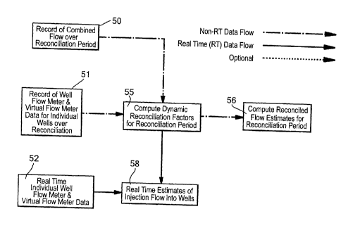
FIG. 5 schematically shows the computation of
reconciliation factors for a cluster of injection wells for
CA 02694014 2010-01-19
WO 2009/024544
PCT/EP2008/060748
- 9 -
reconciled estimates, and optionally for the validation of
individual well meter readings.
FIG. 6 shows schematically how data from well zonal
injection testing is used to construct the well zonal
injection estimation models and how real time estimates of
injection for individual zones are generated.
FIG. 7 shows the steps in the use of the data to
generate setpoints for the surface injection control and
the subsurface ICV settings to control injection rates and
pressures at each zone.
DETAILED DESCRIPTION OF PREFERRED EMBODIMENTS OF THE
INVENTION
FIG. 1 depicts a fluid injection system comprising a
cluster of injection wells which receive the injection
fluid from a common source 30 for which a header flow meter
28 measures overall injection flow rate, and a header
pressure transmitter 25 measures the fluid supply pressure.
The injected fluid may comprise water, steam, natural gas,
carbon dioxide, nitrogen, chemical enhanced oil recovery
(EOR) agents and/or other fluids.
The fluid is distributed via an injection manifold 21
to the cluster of injection wells, each with an isolation
valve 16 on the well flowline 15. Injection well 1 is
shown in detail, and may be taken as representative of the
other injection wells in the cluster. Well 1 comprises a
well casing 3 secured in a borehole in the underground
formation 4 and production tubing 5 extending from surface
to the wellbore in contact with the underground formation.
The flow path in the annulus between the tubing and the
casing is blocked by a packer 6. The well 1 further
includes a wellhead 10 provided with well variable
monitoring equipment for making well variable measurements,
typically a THP gauge 13 for measuring Tubing Head Pressure
(THP). Optionally, the well monitoring equipment comprises
a Flowline Pressure (FLP) gauge 12 for monitoring pressure
CA 02694014 2010-01-19
WO 2009/024544
PCT/EP2008/060748
- 10 -
in the well surface flowline, and an injection fluid
flowmeter 14. Optionally, an injection choke valve will be
available for regulating the injection flow into the well,
and further optionally, a means of controlling the valve
automatically via an actuator 11, of which position will be
recorded. Optionally, there may be downhole monitoring
equipment for making subsurface measurements, for example a
Downhole Tubing Pressure(DHP) Gauge 18. The wellheads of
the injection wells in a cluster may be located on land or
offshore, above the surface of the sea or on the sea bed.
One or more injection wells may also inject into two or
more subsurface zones or branches, with subsurface
configurations typically as shown FIG. 2 and FIG. 3. FIG.
2 illustrates a multizone fluid injection well 80 with
tubing 5 extending to well segments, which form three
distinct producing zones 80a, 80b and 80c, separated by
packers 6. Each zone has means of measuring the variations
of thermodynamic quantities of the fluids within zone as
the fluid injection to each zone varies, and these can
include one or more downhole tubing pressure gauges 83 and
one or more downhole annulus pressure gauges 82. Each zone
will have a means for remotely adjusting the injection into
the zone from the tubing, for example, an inflow (or
interval) control valve (ICV) 81, either on-off or step-by-
step variable or continuously variable. The multizone well
80 further includes a wellhead 10 provided with well
variable measurement devices, for example, "Tubing Head
Pressure" (THP) gauge 13 and "Flowline Pressure" (FLP)
gauge 12, with the most upstream downhole tubing pressure
gauge corresponding to item 18 in FIG. 1.
FIG. 3 illustrates an optional configuration with a two
zone injection well (Zones A and Zone B, separated by
packers 6) with tubing 5 branching into to separate
concentric flow paths to Zone A and Zone B, controlled via
CA 02694014 2010-01-19
WO 2009/024544
PCT/EP2008/060748
- 11 -
inflow control valves ICV A and ICV B, 81, either on-off or
step-by-step variable or continuously variable.
Each zone has means o f measuring the variations of
thermodynamic quantities of the fluids within zone as the
fluid injection to each zone varies, and these can include
one or more shared downhole tubing pressure gauges 83 and
one or more downhole annulus pressure gauges 82 for each
zone.
The well measurements comprising at least data from 13,
82 and 83, position of injection choke 11, and optionally
from 12, 14 and from other measurement devices, as
available, are continuously transmitted to the "Data
Acquisition and Control System" 40. Similarly, the
injection fluid supply measurements 25, 28 are continuously
transmitted to the "Data Acquisition and Control System"
50, in FIG. 1. The typical data transmission paths are
illustrated as 14a and 28a. The data in 40 is stored in the
"Production data Historian" 41 and is then subsequently
available for non-real time data retrieval for data
analysis, model construction and control as outlined in
herein.
Reference is now made to FIG. 4, which provides a
preferred embodiment of the "PU Inj" modelling process
according to this invention. The intent is to generate
sustainably useful models fit for the purpose of the
invention, taking into account only significant injection
system characteristics and effects.
The cluster of injection wells may comprise a number of
n wells indexed i=U¨,n, and the method may comprise the
initial steps of injection testing the wells 60. This is
achieved by performing a series of actions during which
injection to a tested well is varied by adjusting 11,
optionally 16, including closing in the well injection for
a period of time, and then injection of the tested well is
started up in steps such that the tested well is induced to
CA 02694014 2010-01-19
WO 2009/024544
PCT/EP2008/060748
- 12 -
produce at multiple injection rates over a normal potential
injection range of the well, at the same time controlling
the other wells in the cluster such as to cause their
tubing head pressures or optionally flow meter readings to
be approximately constant for the duration of the test.
For the duration of time of the test, including the periods
immediate before and after the test, the supply flow 28 and
pressure 25 and all available measurements at the wells are
recorded, which test is hereinafter referred to as a
"Deliberately Disturbed Injection Testing" (DDIT). In this
test, the injection flow rate through the tested well is
inferred by the difference in the header flow between when
the well was closed in and the recorded the header flow
during the test.
Optionally, if a well has a flowmeter, then the
historical information of the variation of flowrate 61 and
other measured variables at the well 62 may be used to
construct a well injection estimation model.
Further optionally, the common supply pressure, as
recorded by 25, may be varied in steps so that the
injection rates of the wells are simultaneously varied.
Optionally, if each well has a flowmeter, the common
supply pressure, as recorded by 25, may be varied in steps
so that the injection rates of the wells are simultaneously
varied.
Further optionally, other methods as described in the
International Patent application PCT/EP2007/053345 may be
used to construct a well injection estimation model. As an
example, a sequence of injection well tests may be
performed such that sequentially each of the wells of the
well cluster is tested for characterization by initially
closing in all the wells in the cluster, and subsequently
starting up injection to one well at a time, in sequence,
with wells individually started up in steps to produce at
multiple injection rates over the normal potential
CA 02694014 2010-01-19
WO 2009/024544
PCT/EP2008/060748
- 13 -
operating range of the well, at the same time the supply
flow 28 and pressure 25 are recorded. From
this sequence
of well tests: (i) an estimate of the injection of a first
well to be started up is directly obtained from the
injection well test of the first well, and the well
injection estimation model is calculated for that well,
(ii) the injection from the second well to be started-up up
is derived from subtracting the injection of the first well
using the well model of the first well already established
and (iii) the injection and well injection estimation model
of the third and any subsequently started well are computed
in sequence of their start-ups, thereby obtaining the well
injection estimation model of each well of the well
cluster.
Given the injection test data 60 as described above,
the "well injection estimation model" for each well i is
expressed as yi(t)=ai+fi(Pouii(t),u2i(t),...), wherein the value (t)
is the estimated injection into well i as monitored
throughout the period of time t of the well test, and
are the dynamic measurements at well i that are
determined during the well test, including one or more of
Items 12, 13, 11, 25 in FIG. 1. The scalar ai and vector
with f(P012101720.-)=0 for all Pi for some nominal set of
well operating measurements are
computed to provide
a mathematical least squares best fit relating Y(t) and
In this embodiment of the mathematics,
f(Pou1(0,u2W,..) can be viewed as the "gain" of the "well
production estimation model" about the nominal operating
point /110/72Ø-, and ai can be viewed as the "bias" or
"offset" or "anchor" about that operating point, and the
function(al) f(Pou,(0,u,W,..) can be linear or non-linear but
in any case parameterised by the vector A;
CA 02694014 2010-01-19
WO 2009/024544
PCT/EP2008/060748
- 14 -
The "well injection estimation model" 64 is then
where ',(t) is the estimate of
injection flow of well i at time t. The
model 64 may then
be combined with real time values of tt1(0,tt2(0."
, item 65 in
FIG. 4, to give j)jo, the estimated well injection fluid
flow of well i, item 52 in FIG. 4.
Optionally, if the injection well flow meter 14 is
operational and providing good estimates, the estimates of
injection rate YJO may also be replaced by the actual
reading of 14, denoted MO per Item 66 in FIG. 4. In this
case, the estimates ',(t) are the backup for the actual
injection flow reading MO. The measured MO and
estimated 2,(0 injection rates are recorded in the
Production Data Historian, 41.
Given injection estimates 9,(0, or actual injection flow
(t) for n wells indexed i=1,2õ,n
readings Yi the
invention
provides for improving the individual well injection
estimates or injection measurements via a dynamic
reconciliation process with the total header measurement
FIG. 1, Item 28. This extends
the dynamic reconciliation
method of PCT/EP2005/055680 to injection wells and to the
case where one or more the component measurements is a
meter, as opposed to an estimate.
Let the total header measurement FIG. 1, Item 28 be
denoted by s(t). In general, due
to the topology of flow
per FIG. 1, s(t)=(t), where for simplicity, 9(t) denotes
either the measurement 14 in FIG. 1 / 66 in FIG 4, or the
virtual meter estimate 52 for the well i. In general, over
n
a time period T the relation s(t)=(t) will not hold due
CA 02694014 2010-01-19
WO 2009/024544
PCT/EP2008/060748
- 15 -
to meter and estimate inaccuracies as well as measurement
noise. A dynamic reconciliation process 55 to improve the
accuracy of the estimates and to identify estimates which
are inaccurate may then be optionally implemented as per
FIG. 5. The process works on a pre-determined specified
time interval. In that time interval, the models of the
estimates are varied in a limited way so that the estimate
of total injection
YJO substantially matches the measured
value s(t) over the entire specified time interval. The
process is then repeated in the next time interval.
A simple embodiment of the above may assume that 9J0
is related to the true value of flow by S'i=ciYi di, where Yi
is the true value, and ciodi are gain error and bias errors.
Dynamic reconciliation over a period of time T may then be
based on an integrated squared error criterion
-2 -2
E(T)= s(t)¨E5),(t) dt = s(t)¨E(ci 5),(0+ di) dt which is to be
minimised by appropriate choice of ci , di, i = 1,2, ..., n In
general, it is easy to check the bias terms of the
measurement or estimate error, di, i = 1,2, ..., n for example by
shutting off flow. Therefore neglecting the di, i = 1,2, ..., n
-2
terms, the error model then becomes E(T)= s(t)¨Ecji(t) dt
which is a conventional least squares form solvable by an
expert in the field given discrete samples of s(t) and 9J0
at intervals within T, respectively FIG. 5, Items 50 and
51, to give reconciliation factors ci,i= 1,2, ..., n The
computed reconciliation factors are then used to compute
that best current real time estimate of flow as ,
CA 02694014 2010-01-19
WO 2009/024544
PCT/EP2008/060748
- 16 -
Item 58.
Similarly, for the period T, the best estimates
of injection flow to the wells are given by
Item 56.
The computation of the factors ci,d,i=1,2õ..,n applied to
each of the well injection estimation models at each
reconciliation computation for a particular reconciliation
period may be related further to the factors ci,d,i=1,2õ..,n
from the previous reconciliation period, to reflect a
balance between the information available in the previous
reconciliation period and the current reconciliation
period. To save on the computational memory load, the
computation may optionally use the recursive least squares
method of, for example, the textbook "Lessons in Digital
Estimation Theory", J.M. Mendel, Prentice Hall 1987.
The computation of the factors ci,d,i=1,2õ..,n may also be
subjected to additional auxiliary constraints or
optimization target terms, such a limitation of 0=1,2õ..,n
deviation from 1 to be less than 10%, or minimizing the
-
difference in total volumes A(T)= f[s(t)idt ¨ Ecji(t) dt . The
foregoing additional auxiliary constraints or optimization
targets lead to a problem formulation as a general convex
quadratic programme, efficiently solvable using standard
numerical iterative optimization tools.
For the wells that have at subsurface (or downhole)
level, multiple fluid injection zones or branches with
appropriate instrumentation, the invention provides a
method for the allocation of injection to the individual
zones of the wells and zones and the control of pressures
and injection rates to the individual zones. In the sequel
the details are illustrated by reference to a multizone
well of FIG. 2, but the principles are equally applicable
to a multi-branch or a multilateral well.
CA 02694014 2010-01-19
WO 2009/024544
PCT/EP2008/060748
- 17 -
With reference to FIG. 6, the procedure leading to the
generation of "Surface and Zone Prediction Models" for a
multizone injection well with m zones indexed j=1,2õttt, is
described as follows: A "Deliberately Disturbed Multi
Zonal Injection Test" (DDMZIT) 85 is conducted during which
the injection from each zone is varied by changing the ICV
of the zones as well as the surface injection control valve
11. Well surface flow 14 and tubing head pressure 13
measurements are recorded, and optionally measurements 11,
12. Similarly, downhole annulus 82 and tubing 83
pressures and ICV positions 81 are recorded throughout the
test. The DDZIT data 85 is used to generate "subsurface
models" 88a,b,c as well as "surface injection estimation
model" 88d. The "surface injection estimation model" of a
well is of the form Y=fs(us,vs,t), valid for a range of us,vs
within a set of real numbers UsxVsxT, wherein the vector Y
is the fluid injection rate of well, us is the vector of
measurements at the well, vs is the surface injection
control valve position, and t is time. In a preferred
embodiment, u5 can be the tubing head pressure 13 and the
downhole tubing pressure 18 or alternatively, the tubing
head pressure 13 and the flowline pressure 14. The
function f
J,5 is constructed using the data from the zonal
well test 85 and optionally, from surface well testing as
outlined previously.
The zonal well test data 85 is used to generate a set
of "subsurface models": (i) "Zonal ICV Models" 88a, (ii)
the "Zonal Inflow Model" 88b, and (iii) "Tubing Friction
Models" 88c. The "Zonal ICV Models" will be of the form
yi=ki(upvi,t), valid for a range of ttpvpt within a set
U.xV Y
. ,
xT, wherein . is the fluid injection into zone j u.
J J
is the vector of measurements at zone j, most commonly the
CA 02694014 2010-01-19
WO 2009/024544
PCT/EP2008/060748
- 18 -
annulus and tubing pressure gauges 82 and 83 in FIG. 2, and
vi is the manipulated variable at zone j, the ICV opening.
The "Zonal Inflow Model" will be of the form
yi=li(uppRij), valid for a range of uppRjj within a set
U.xP.
R,xT wherein y. is the fluid injection into zone j, u.
is the vector of measurements at zone j, in particular the
annulus pressure gauges 82 in FIG. 2, and pRi is the
underlying reservoir pressure for zone j, which is
obtained from the downhole annulus pressure 82 after the
zone is closed in for a period of time. The zonal inflow
/j characteristic and reservoir pressure PR; can be expected
to decline with time t. Finally, the "Tubing Friction
Models" will be of the form yik=mik(uik), valid for a range
of u. within a setUjk, wherein the vector yjk is the fluid
flow between from zonej to zone kr ufl, is the vector of
measurements at zone i
J and zone k, in particular the
downhole tubing pressure gauges 83 in FIG. 2. The "Tubing
Friction Models" 88c are required due to the daisy chain
configuration of the extended reach wells, and may
incorporate pressure differentials due to fluid weights
within the tubing arising from differences in vertical
elevation. Given the Multizonal Well test data 85, the
data driven procedures for constructing the particular
"Zonal ICV Models" yi=ki(upvi,t), the "Zonal Inflow Models"
yi=/i(uppõi3O and the "Tubing Friction Models" yik=mijuik) is
as previously outlined in "PU RTM", "PU DDPT" and "PU RTO".
From the "Zonal ICV Models" 88a, and real time
subsurface pressure and ICV opening data from the Data
Acquisition and Control System 40, real time estimates of
the zonal production flows may be estimated 89. The "Zonal
Inflow Models" 88b may also be used to estimate 89. As
CA 02694014 2010-01-19
WO 2009/024544 PCT/EP2008/060748
- 19 -
the total of the zonal injections should equal the surface
injection, the zonal injection estimates may be dynamically
reconciled with the surface injection measurement 14 over a
period of time, using the methods previously outlined
herein to obtain the daily reconciled zonal injection
estimates 93.
Similarly, the injection estimate from the multizone
extended reach well can be combined with estimated
productions from the other wells in the cluster 92, and
reconciled with the overall well cluster injection header
flow measurements 28 in FIG. 1, to give item 94 in FIG 6.
Given surface and subsurface models,
= fs (us vs 9 yi = ki (Ui 91)i , yi = PRi Y jk = n
jk(U jk) f
j,k=1,2,...,m, and boundary conditions of zonal reservoir
pressures PRJ, time t, flowline pressure 12, and the
relation Y=2,i=1Yi, it should be clear to an expert in the
field that the resulting system of equations is similar to
a network problem with pressure measurements at its nodes,
and is solvable for both the flows and pressures
Y,ypui j=1,2".õIn, for given combinations of v5,vpj=1,2¨in.
Hence the relations above constitute the "Surface and Zonal
Injection and Pressure Prediction Model" 97, of FIG. 4.
Optionally, the difference form of the relations of 97 may
be used:
AY = (Au Av ) AY = En' Ay . Ay . = . (Au . Av .) Ay = (Au . )
,vs s 9 S j=1 J r J J J r J r
Ay ik = ik) j, k 1,2,...,m , where AY denotes differential
changes to Y and fs denotes the first order
approximation of fs with respect to the differenced
variables at us,vs, and so on. The differenced form is
useful as it is even more easily solvable and allows
consideration of changes only as a result of changes in the
CA 02694014 2010-01-19
WO 2009/024544
PCT/EP2008/060748
- 20 -
manipulated variables, and the results of the computation
to be consistent with the current state of the multizone
well as measured in real time in terms of the measured
downhole and surface pressures, us, ui, j =1,2,= = =,n
Once the "Surface and Zonal Injection and Pressure
Prediction Model" 97 is available, the control of the well
injection and pressures is implemented as per the workflow
in FIG. 7. If the required surface and ICV control
setpoints vs, j = 1,2,. .,m were continuously variable based on
the desired zonal and surface production and pressure
levels, then v5,vi,j=1,2,...,m can be computed using an
continuous optimization framework 100 as follows:
max
VS ,vi
subject to K constraints cjY,u,v,õypupvp j=1,2õ.,a00,
k=1,2""JC.
where R is the objective function 98a for the injection
well to be maximized by varying v5,v,j=1,2".õIn, the
manipulated variables at well and its zones, subject to K
constraints 98b on Yji,v,ypupvp j=1,2_111, the well and
zone injection, the well and zone measured variables and
the well and zone manipulated variables, respectively. The
optimization objectives and constraints may come from an
overall field or reservoir management plan 99.
However, it is currently the state of the art that the
subsurface ICV positions, vpj=1,2,",m, can only vary a
limited number of positions, say, N. The surface
injection control may also by restricted to the same number
of positions. Hence, since the number of zones per
extended reach injection well is limited to date to
there are only Nm+ipossible combinations for
and it is the preferred approach to enumerate the entire
CA 02694014 2010-01-19
WO 2009/024544
PCT/EP2008/060748
- 21 -
range of possibilities to produce an Enumeration Table 103.
m+1
Given the enumeration based on the Afpossible
combinations for vs,l'pj=1,2--/n, and the surface and zonal
injection and pressure prediction model 97, it is straight
forward to filter the table 103 as per the constraints 98b
and rank the remaining alternatives using the objective
function 98a. The best set of setpoints for
is therefore computed 101.
The set of "optimised setpoints" is then available for
further action. Reference may be made to the Applicant's
International Patent Application PCT/EP2007/053348, for a
variety of possible actions to suit operational
requirements following the computation of the setpoints.