Note: Descriptions are shown in the official language in which they were submitted.
CA 02694037 2010-01-29
WO 2009/026386 PCT/US2008/073751
FIRING PATTERNS FOR DEEP BRAIN TRANSCRANIAL MAGNETIC
STIMULATION
CROSS REFERENCE TO RELATED APPLICATIONS
[0001] This application claims priority to the following applications: U.S.
Provisional
Patent Application Serial No. 60/956920, filed on August 20, 2007, titled
"FIRING PATTERNS
FOR DEEP BRAIN TRANSCRANIAL MAGNETIC STIMULATION."; U.S. Provisional
Patent Application Serial No. 60/970958, filed on September 9, 2007, titled
"PULSING
MULTIPLE INDEPENDENTLY TRIGGERED ELECTROMAGNETS FROM ONE OR
MORE ENERGY SOURCES."; and U.S. Provisional Patent Application Serial No.
61/077488,
filed on July 2, 2008, titled "DIFFERENTIAL PULSE PATTERNS IN PARALLEL
STIMULATION ARRAYS." Each of these applications is herein incorporated by
reference in
its entirety.
INCORPORATION BY REFERENCE
[0002] All publications and patent applications mentioned in this
specification are herein
incorporated by reference in their entirety to the same extent as if each
individual publication or
patent application was specifically and individually indicated to be
incorporated by reference.
FIELD OF THE INVENTION
[0003] The devices and methods described herein relate generally to the
triggering of
electromagnets used for Transcranial Magnetic Stimulation.
BACKGROUND OF THE INVENTION
[0004] Transcranial Magnetic Stimulation (TMS) of the brain has been employed
in a
limited way to treat depression refractory to the administration of drugs. The
number of treatable
conditions may significantly increase as the depth of the target increases.
Systems for targeting
neural structures at depth (e.g., Schneider and Mishelevich, U.S. Patent
Application No.
10/821,807, and Mishelevich and Schneider, U.S. Patent Application No. 11/429,
504) may
include multiple electromagnets, the firing of which must be coordinated. TMS
stimulation of
deep targets would potentially permit treatment of a variety of conditions
such as chronic pain,
addiction, obesity, depression, Alzheimer's disease, and Parkinson's disease.
Conventional
rTMS (repetitive transcranial magnetic stimulation) is capable of effectively
stimulating only the
outer cortical layer of the brain, and treats depression indirectly, by
stimulating neural pathways
that run from the prefrontal cortical surface to the cingulate gyrus, rather
than hitting the target
1
CA 02694037 2010-01-29
WO 2009/026386 PCTIUS2008/073751
directly. It is preferable to stimulate deep structures such as the cingulate
gyrus directly, but
when targeting deep neural structures with rTMS, care must be taken to avoid
over-stimulating
superficial structures to eliminate undesired side effects such as seizures or
producing unintended
neural-stimulation results. It is thus necessary to avoid having too many
successive pulses from
the same electromagnet passing through such superficial structures while
targeting the deep
structure.
[0005] To effectively elicit an action potential in a neural structure,
adequate stimulation
must be received in a time period which is less than the minimum time (usually
expressed as
chronaxie) that it takes the target neural membrane to re-polarize. Otherwise
threshold for
generating an action potential will not be achieved. With respect to another
time scale, for a
given neural structure, stimulating pulses must be received within a maximum
effective time
interval such that the effect of the generated action potentials is additive.
Neural elements are
typically highly interconnected and the actual final target element to be
stimulated will receive
inputs from multiple sources
[0006] The pulse-rate frequency from any given electromagnet location is
preferably
limited, typically to a rate of less than 50 pulses per second (i.e., 50 Hz).
While limiting the
frequency from a single stimulating location will protect structures
superficial to the deeper
target, it may be impossible to effectively stimulate a deep target because of
the rapid fall off of
the magnetic field (roughly 1/(distance)2 at short distances). Thus, different
trajectories must be
stimulated in turn. We have previously suggested accomplishing this by either
moving the
electromagnets, as is described in Schneider and Mishelevich, U.S. Patent
Application No.
101821,807 ("Robotic apparatus for targeting and producing deep, focused
transcranial magnetic
stimulation") or by sequentially firing electromagnets located at distributed
locations. The
approach of this latter case may avoid over-stimulating superficial neural
structures at a single
location and causing seizures or other undesired impacts, but to be
successful, the pulsed
magnetic fields must reach the target at a higher effective rate of
stimulation than the pulsed
magnetic fields hitting superficial tissue. The coordination of the
orientation, timing, frequencies
and power levels for controlling multiple magnets to stimulate one or more
targets, and
particularly deep tissue targets is a difficult task that has not yet been
effectively accomplished.
Described herein are methods, devices and systems for accomplishing this.
[0007] Furthermore, different tissues may have differing requirements in terms
of the
amount of fimction augmentation or suppression that they require, or that they
can tolerate. For
example, when seeking to suppress the activity of a remote target using slow
rate rTMS
delivered from multiple intersecting pathways, one or more intermediate
tissues may be
2
CA 02694037 2010-01-29
WO 2009/026386 PCT/US2008/073751
inadvertently suppressed in the process, when, in fact, such tissue(s) require
functional
augmentation.
100081 For example, Isenberg et al., and others, have shown that either fast
rate (e.g., 10
Hz) rTMS applied to the left dorsolateral prefrontal cortex (LDLPFC) or slow
rate rTMS (e.g., 1
Hz) applied to the right dorsolateral prefrontal cortex (RDLPFC), are
effective treatments for
depression. Published studies have involved treating either of those two
targets. The practical
limitations of currently available equipment prevent the alternative or
concurrent slow right and
fast left treatment. These limitations stem from logistical difficulties in
positioning TMS coils,
and applying selected pulse parameters at the correct positions.
[0009] Arrays of multiple magnetic coils have been proposed. For example,
Ruohonen
et al. (1998) modeled in software an array of small adjacent magnets intended
to stimulate the
outer cortical surface of the brain. While power requirements are calculated
in this study, no
specific means for delivering or switching that power are disclosed. Ruohonen
et al. (1999)
modeled in software a multi-coil array for the purpose of limb rehabilitation.
Again, no specific
means for switching or delivering power to the appropriate coil were
described. Instead, "the
multichannel design allows the stimulus to be moved without moving the coils.
This is
accomplished by individually adjusting the strength and direction of the
current in each coil."
Han et al. (2004) proposed a multiple coil array, but they also had no
particular strategy for
powering the coils other than turning them on simultaneously, and describes,
"[i]n the
multichannel magnetic stimulation, it is assumed that the predetermined
optimal currents are fed
in-phase to the coils. Therefore, all the channels are generally ON state when
a stimulation pulse
is applied to the subject."
[00010] Thus, there is a need for appropriately controlling the stimulation
from magnets
so that the stimulation can be focused on deep tissue without creating
undesired stimulation or
inhibition effects in tissue superficial to the deep target. Furthermore, if
effects are to be induced
upon the intervening neural structures, those effects should be calculated,
controllable, desirable
effects. ]Me control of the system must allow powering of the array of magnets
by tapping the
stored charge from one or more sources, and delivering them precisely, under
the appropriate
circumstances to each coil, individually. There is also a need for a system by
which the pulse
rate, power and pattem of stimuli delivered through intermediately juxtaposed
brain tissue may
be different in the different coils of the array, thereby better suiting the
characteristics and
therapeutic needs of that intermediate brain tissue as well as that of the
principal target.
Depending on the number of electromagnets, the capacity of the power sources,
and other
factors, it may be more appropriate to supply power for the triggering of the
electromagnets from
3
CA 02694037 2010-01-29
WO 2009/026386 PCT/US2008/073751
either a single power source or multiple power sources. Systems, devices and
methods to
address these needs, as well as others, are described in greater detail below.
SUMMARY OF THE INVENTION
[000111 Described herein are methods, devices and systems for controlling the
firing of
electromagnets located at different positions to stimulate at least one brain
region, including deep
brain regions. The firing may be performed at fixed, random, or mixed fixed
and random
intervals, and/or at different pulse rates. In general, the methods described
herein include
methods of focusing stimulating from multiple magnets on one or more brain
region so that
energy from the magnets sums in a desired brain region to trigger firing of
neurons (e.g., action
potentials) in the target brain regions without triggering firing in adjacent
(and particularly
superficially located) brain regions. The methods further include controlling
the timing, rate,
and power of each magnet in an array of magnets to achieve transcranial
magnetic stimulation so
that energy applied by the magnets to non-target regions is below a threshold
for stimulation and
energy applied to target regions is above the threshold. Furthermore, the rate
of stimulation
(e.g., the rate that action potentials are evoked) in target regions may be
controlled to modulate
the effects of stimulation of a target region.
[000121 In one embodiment, one or more pulses can be generated (e.g., 3, 2, 2,
1, 5 pulses
etc.) at one location before moving on to the next. Alternatively, some or all
the pulses can be
concurrently fired from two or more locations. Instead of whole trains of
pulses stimulating a
given volume of superficial tissue, relatively few pulses per a given period
of time may be fired
from locations close to, and potentially stimulate the superficial tissues,
but the magnetic pulses
reaching the deep target location from a plurality of magnets may combine to
form a pulse train
that activates the desired volume of target tissue. The plurality of
electromagnets referred to
herein may be in fixed positions or may be mobile (as in Schneider and
Mishelevich, U.S. Patent
Application No. 10/821,807). The net effect at the target location is due to
combined elements
of temporal and spatial sununation.
[00013] This approach may also be used to take advantage of the individual
properties of
different brain regions, permitting each region to be stimulated with the
pulse sequence that
maximally contributes to the overall intended effect of the treatment. For
example, adverse
effects may result if pulse rates exceed 3 Hz when the pulse trajectory passes
through the right
dorsolateral prefrontal cortex on the way to a cingulate target. Consequently,
it may benefit the
overall treatment strategy to limit the rate of pulses passing through the
right dorsolateral
prefrontal cortex, even though a faster pulse rate would help the temporal
summation effect.
4
CA 02694037 2010-01-29
WO 2009/026386 PCT/US2008/073751
[00014] By coordinating the activity of a plurality of electromagnets, each of
which must
receive a certain amount of pulsed electrical charge at specific times with
respect to one another,
the devices, methods and systems described herein may control the stimulation
of one or more
brain regions, including regions previously thought to be too deep for
controlled transcranial
magnetic stimulation. This process may occur in configurations in which the
charge pulses
received by these electromagnets are simultaneous, and when the charge
delivery among these
coils is not simultaneous.
1000151 In one variation, a single power source has an output directed to
multiple
electromagnets by controlling which driver is gated to conduct to a given
electromagnet via a
distributor element controlled by a stimulation controller. In another
variation, multiple power
sources (for example, one for each electromagnet) are each controlled via an
associated driver.
The gating of the drivers is determined by a distributor element controlled by
a stimulation
controller. Single power source and multiple power source configurations can
be mixed in a
single system.
[00016] These methods, systems and devices may also allow a neuromodulation-
produced
energy source to simultaneously deliver different effects to different neural
tissues. For example,
multiple stimulation trajectories or multiple stimulation sources (e.g., TMS
coils) may be
controlled to achieve targeted stimulation. Each of these sources may be
capable of independent
fanction. The cumulative effect of the multiple sources at the intersection of
their paths, as well
as the independent effects of each source in proximal tissue, are calculated
and controlled by the
system described.
BRIEF DESCRIPTION OF THE DRAWINGS
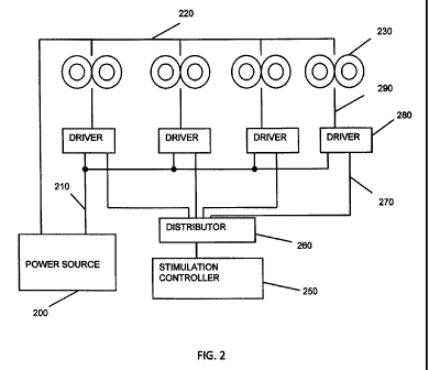
[00017] FIG. 1 shows five coil-pair sets of electromagnets.
[00018] FIG. 2 illustrates one embodiment of a system for stimulating neuronal
tissue
deep within a subject's brain in which the power for the electromagnets is
provided by a single
energy source.
1000191 FIG. 3 illustrates another embodiment of a system for stimulating
neuronal tissue
deep within a subject's brain in which the power for the electromagnets is
provided by multiple
individual energy sources.
1000201 FIG. 4 illustrates various forms of control that can be provided for
the plurality of
coils.
[00021] FIG. 5 shows an array of 3 energy sources around a patient's head,
shown in
frontal external view (left), and in cross section (right).
5
CA 02694037 2010-01-29
WO 2009/026386 PCT/US2008/073751
[000221 FIG. 6 is a table that illustrates three variations of ways in which
the coils such as
those shown in FIG. 5 may be activated in order to achieve a desired effect,
including three
threshold-based (action-potential-elicited versus no- action-potential-
elicited) calculations.
[00023] FIGS. 7A and 7B show two exemplary arrays of 4 (double) stimulator
coils
positioned around a patient's head.
[000241 FIG. 8 is a table that tallies the effect of different pulse patterns
in the coils shown
in FIGS. 7A and 7B in a manner that considers distance from each coil, and the
strength of the
magnetic pulses (measured continuously rather than as a binary variable), and
the resultant effect
upon the target structure relative to interposed superficial structures.
[00025] FIG. 9 is an flowchart showing one variation of a Transcranial
Magnetic
Stimulation method, as described herein.
1000261 FIG. 10 illustrates distances measured from the bottom of cortical
sulci to a deep
target, in this example, the cingulate bundle.
1000271 FIG. 11 is one variation of a portion of a method of determining
stimulation
parameters for Transcranial Magnetic Stimulation.
DETAILED DESCRIPTION OF THE INVENTION
1000281 The Transcranial Magnetic Stimulation (TMS) methods, devices and
systems
described herein are capable of triggering action potential (including
specified patterns of action
potentials) in one or more target brain regions without trigger action
potential sin nearby non-
target regions, including regions that are superficial (e.g., between the
target region and the
external magnets(s) stimulating the brain). These TMS systems may support a
variety of action
potential firing patterns by controlling the pulsing of multiple,
independently triggerable,
electromagnets from one or more energy sources. The system may also monitor or
control the
one or more power supplies so that there is sufficient capacity from the power
supplies so when a
given pulse is triggered, adequate power is available to deliver a stimulus
from each
electromagnet as needed to trigger the desired action potentials from the
target brain region.
[000291 FIG. 1 illustrates a configuration incorporating five electromagnets
110, 120, 130,
140, and 150 which may be used as part of a TMS system as described herein.
The
electromagnets need not be of equal size, and do not have to be in a uniform
relationship to each
other. The electromagnets may move as a group (say on a gantry or robotic arm)
and/or in
relationship to each other over time. For example, the electromagnets may be
moved during
stimulation (TMS) or they may be fixed during stimulation. In FIG. 1, a target
neural (brain)
tissue region 170 is illustrated. This region need not be equidistant from the
electromagnets.
6
CA 02694037 2010-01-29
WO 2009/026386 PCT/US2008/073751
Two or more electromagnets must be included; in the description of the
embodiments illustrated
in FIGS. 2 and 3, four electromagnets are incorporated.
[00030] In general, the devices and systems described herein may be used to
stimulate one
or more regions of the brain. As used herein "stimulation" of a brain region
may refer to the
eliciting of one or more (or a series of) action potentials from the brain
region. Deep brain
regions in particular may be stimulated with these devices and methods. As
used herein the
phrase "deep brain regions" may refer to cortical and sub-cortical brain
regions, or just sub-
cortical brain regions (e.g., regions below the subject's cortex). In some
variations, multiple
brain regions (including a cortical and a sub-cortical brain region, two or
more sub-corkical
regions, etc.) may be stimulated. For example, a complex pulse rhythm such as
the "theta"
pattern (Huang et al., 2005) on one region of the brain may facilitate TMS-
induced
neuromodulation effects in another part of the brain. Thus, the systems
described herein may be
used to simultaneously stimulate such a pattern in one region while
simultaneously stimulating
another region.
[00031] In order to stimulate one or more brain regions, the TMS systems
described
herein control the plurality of electromagnets to trigger pulses of an
appropriate strength,
duration and frequency (including complex patterns of stimulation), at each of
the plurality of
electromagnets so that only target brain region(s) are activated. Triggering
of pulses can be done
mechanically (e.g., through notches in a cam) or electronically using a built-
in fixed, random, or
mixed pattern or such patterns can be generated under computer control.
1000321 In general, the system may generate appropriate firing patterns for
each of the
plurality of electromagnets in the system. The "firing pattern" may refer to
the duration of a
pulse, the frequency of the pulse, and the intensity (strength) of the pulse
(e.g., the
current/voltage applied to generate the pulse). The system typically controls
and coordinates the
firing patterns of tall of the electromagnets. For example, the electromagnets
may be fired in a
sequential order (e.g., first electromagnet, second electromagnet, third
electromagnet, etc.) or in
some other order (including random or pseudo-random). An example of a
sequential fring
pattern is shown in Table I and of a random firing is shown in Table 2, below.
In Table 1,
electromagnets at five different locations, A through E represented in the
table columns, are
triggered sequentially as the process steps through times I through 10
represented in the table
rows. The objective is to minimize the number of pulses received by tissues
close to a given
electromagnet to avoid undesirable side effects while maximizing the number of
pulses
stimulating the target. Each pulse must be of sufficient duration so that the
neural membrane
will not' re-polarize. For example, the chronaxie of a typical cortical neuron
is 450
microseconds. The electromagnets are physically distributed such that tissues
close to one
7
CA 02694037 2010-01-29
WO 2009/026386 PCT/US2008/073751
electromagnet location (e.g., location "A") will be little impacted by pulses
from a different
location (location "B"). In Table 1, for location A, pulses may be triggered
at time steps 1 and 6,
so at the end of time step 10, two pulses have passed through neural tissue
from the
electromagnet at location A. The same effect will be true for electromagnets
at locations B
through E. The common target, however will have received a pulse at each time
step, albeit at a
someone lower magnitude because it is further away than tissues close to the
electromagnets at
locations A through E. As demonstrated, at the end of 10 time steps, tissues
near the individual
electromagnet locations A through E will have received only two pulses where
the target deep
location will have received ten pulses.
[00033] TABLE 1: SEQUENTIAL FIRING PATTERN
LOCATION
TIME A B C D E TARGET
1 1 1
2 1 1
3 1 1
4 1 1
5 1 1
6 1 1
7 1 1
8 1 1
9 1 1
10 1 1
CUM 2 2 2 2 2 10
TOTALS
[00034] The TMS systems described herein may include control logic that
coordinates the
firing pattern, as well as the timing, strength and duration of the pulses
applied by the
electromagnets. This control logic (which may be part of a controller, and may
be hardware,
software, or both) may receive inputs regarding the subject's target anatomy
(e.g., the location of
one or more targets relative to the electromagnets), as well as information
regarding the status of
the power supply(s) indicating available power. Finally, inputs such as the
desired rate of evoked
action potentials for a target region may also be included. Additional inputs
may be used as
well. These inputs may help the control logic to determine the stimulation at
each of the
electromagnets, including what the firing pattern should be.
[00035] An example of a random firing pattern is demonstrated in Table 2. In
this
example, the same net number of pulses is delivered to tissues close to the
electromagnets at
locations A through E while the deep target receives 10 pulses, similar to the
pattern shown in
8
CA 02694037 2010-01-29
WO 2009/026386 PCTIUS2008/073751
Table 1. Sequential and random firing patterns can be mixed to produce the
same results, and
more than one pulse can be triggered at a given time step before moving on to
the next time step.
Some or all the pulses can be simultaneously fired from two or more locations.
[00036] TABLE 2: RANDOM FIRING PATTERN
LOCATION
TIME A B C D E TARGET
1 1 1
2 1 1
3 1 1
4 1 1
5 1 1
6 1 1
= 7 1 1
8 1 1
9 1 1
1 1
CUM 2 3 1 2' 2 10
TOTALS
[00037] The time interval between time steps 1 through n may be tailored to
deliver the
pulses at a rate that is faster than the interval at which the target neural
elements (neurons of the
10 target brain region) will re-polarize; at this faster rate, the threshold
for the target neural elements
will be exceeded and desired effective stimulation may occur, triggering an
action potential. The
firing rate of the individual electromagnets at locations A through n (and
thus the combined
pulse rate that will be delivered at the target location) depends on the
number of those individual
electromagnets. For example, to achieve a pulse rate at the target to be 1000
Hz, if there are five
individual electromagnets (e.g., A through E), this can be achieved by
stimulating those five
electromagnets at an effective rate of about 200 Hz each. If there are three
only individual
electromagnets (e.g., A through C), this can be achieved by stimulating those
five electromagnets
at an effective rate about 333 Hz each. All of the electromagnets need not be
fired at the same
frequency to achieve the effect. For example to get a pulse rate of 1000 Hz at
the target, two of
three electroinagnets could have an effective firing rate of 400 Hz and the
third could have an
effective firing rate of 200 Hz. It is also not necessary that the
electromagnets be of uniform
type or size. In any situation involving random firing, the time interval can
vary as well as the
firing sequence.
9
CA 02694037 2010-01-29
WO 2009/026386 PCTIUS2008/073751
[00038] The system may also control the firing pattern in order to achieve a
desired rate of
stimulation of the target tissue (e.g., a rate of action potential firing).
For example, the system
may control the electromagnets so that high pulse rates (e.g., 1000 Hz) may be
achieved for only
a fraction of a second, for example over 5 successive pulses, closely spaced,
one from each of 5
electromagnets, followed by a pause. In such a case, the "1000 Hz" pulse burst
may be
experienced by neurons as a single stimulation. Provided that a sufficient
period of wait (e.g.,
0.2 seconds) separates the rapid (e.g. 1000 Hz) multi- electromagnet bursts,
the net effect
experienced by a deep target tissue will of a much slower pace, for example,
between 5-50 Hz.
The same principle may be applied to the production of temporally summated
multi-
electromagnet bursts in the production of slow-rate or fast-rate rTMS. For
example, even if 5
electromagnet are discharged once each at a 1000 Hz rate, so long as about 1
second separates
the overlapping bursts (e.g., the bursts summed in the target tissue), the
effective pulse rate and
safety profile experienced by a given brain part will be just short of 1 Hz.
Thus, by firing each
electromagnet once, each in rapid (e.g., 1000 Hz) succession (a "burst"), but
then waiting 0.2
seconds to 1 second between bursts, we can get temporal summation and the
safety of normal
rTMS rates.
1000391 The TMS systems described herein may therefore attend to the overall
stimulation
pattern while controlling each electromagnet (or groups of electromagnets)
individual firing
rates, durations and strengths. In general, the stimulation of target tissue
results from the
temporal and spatial summation of the effect of the applied electromagnetic
field at the target
tissue. Thus, the system determines the appropriate firing pattern for all of
the electromagnets as
well as the individual firing (strength, duration and rate) for each
electromagnet so that the firing
of each electromagnet results in a sub-threshold energy for the non-target
tissue, but the focused
energy on the target tissue is above-threshold. As indicated, controlling the
power applied by the
system is one part of this control. In general, each electromagnet may be
powered by a single
power source, multiple power sources, or one power source may be used to power
multiple
electromagnets.
[00040] FIG. 2 illustrates an embodiment of a TMS system in which power for
the
electromagnets is provided by a single energy source. One output of power
source 200 is
provided in common via connection 220 to all of the electromagnets 230. While
four
electromagnets 230 are shown in the figure, any number feasible in the applied
geometry can be
powered. The firing of the individual electromagnets is determined by
stimulation controller
250, which activates distributor 260 to select the appropriate driver 280
which when selected at
the given time delivers power via connection 210 from power source 200 to the
associated
electromagnet 230 via connection 290.
CA 02694037 2010-01-29
WO 2009/026386 PCTIUS2008/073751
[00041] FIG. 3 illustrates an embodiment in which power for the electromagnets
is
provided by individual power sources. One output of all the power sources
(e.g., power sources
A through D) 300, 302, 304, 306 is provided in common by connection 320 to all
the
electromagnets 330, 332, 334, 336. Although four electromagnets 330, 332, 334,
336 are shown
in the figure, any number of electromagnets feasible to the applied geometry
can be powered.
The firing of the individual electromagnets in this example determined by
stimulation controller
350, which activates distributor 360 to select the appropriate driver (e.g.,
drivers A through D)
380, 382, 384, or 386 which when selected at the given time delivers power via
associated
connection 390, 392, 394 or 396 from respective power source 300, 302, 304 or
306 to the
associated electromagnet 330, 332, 334 or 336. The controller 350 may run the
control logic
coordinating the stimulation of the target while avoiding stimulation of non-
target regions.
[00042] In either variation illustrated in FIG. 2 and FIG. 3, more than a
single
electromagnet can be pulsed simultaneously, so long as the power source (e.g.,
FIG. 2) or power
sources (e.g., FIG. 3) have sufficient capacity. As mentioned, the control
logic may determine
the appropriate output based on the available capacity of the power source(s).
This capacity may
be monitored directly (e.g., by one or more inputs), based on specification,
or based on
calculation or estimate.
[00043] FIG. 4 illustrates various examples of control of the firing pattern
and excitation
of the electromagnets (coils) that can be provided for the plurality of coils
in accordance with the
present invention as above described. Electromagnet charge storage 400 may be
divided into
Single Source methods 410 and Multiple Source methods 420. Single Source
methods 410 may
be subdivided into categories, as shown in FIG. 4. Single Source Synchronous
pulses 411 are
used in order to make the single power source deliver charge to each of a
plurality of coils at
timings that bear a fixed relationship to one another. Examples may include
simultaneous (414)
pulses, and non-simultaneous (415) pulses. Single Source Asynchronous pulses
412 describe
those in which charge from a single charge storage device is metered to a
plurality of coils in a
manner such that each coil fires based upon a signal other than a time scale
shared by the coils.
The initiation of asynchronous firing may in include, for example, sensing
that a series of pulses
delivered by one coil has finished. Single Source Independent pulses 413
describe those in
which the activity of one coil is not synchronized with, and does not
influence the activity of
another coil. Very large stored charge reservoirs are required to successfully
use this approach.
[00044] Multiple Source methods (420) may also be subdivided into categories.
Multiple
Source Synchronous pulses 421 are used in order to make the single power
source deliver charge
to each of a plurality of coils at timings that bear a fixed relationship to
one another. Examples
may include simultaneous (424) pulses, and non-simultaneous (425) pulses.
Multiple Source
11
CA 02694037 2010-01-29
WO 2009/026386 PCT/US2008/073751
Asynchronous pulses 422 describe those in which charge from a single charge
storage device is
metered to a plurality of coils in a manner such that each coil fires based
upon a signal other than
a time scale shared by the coils. The initiation of asynchronous firing may in
include, for
example, sensing that a series of pulses delivered by one coil has fmished.
Multiple Source
Independent pulses 423 describe those in which the activity of one coil is not
synchronized with,
and does not influence the activity of another coil. This may be more readily
accomplished than
with a single source, as power may be specifically allotted to the activity of
any given coil.
[00045] FIG. 5 shows an array of 3 (double) stimulator coils (referred to
herein as three
`electromagnets') around a patient's head, in an image based in part on image
data from Voxel-
Man 3D Navigator. The head of the subject 505 is shown transected by plane
510. V-shaped
double coil 520 (also designated as coil A or electromagnet A) is composed of
circular coils 521
and 522, and bent at the center where the return path of the current in both
coils is in the same
direction. Similarly, V-shaped double coil 530 (also designated as coil B or
electromagnet B) is
composed of circular coils 531 and 532 joined at a bent center, and V-shaped
double coil 540
(also designated as coil C or electromagnet C) is composed of circular coils
541 and 542, joined
at a bent center. Within the sub-cortical (or "deep") target area 580 (in this
example the left and
right cingulum), there is targeted anatomy 590, in this example, cingulate
fiber bundle 580. In
another embodiment the electromagnets are not V-shaped, but traditional figure-
8 double coils.
In still another embodiment, not all of the axes across the faces of the
electromagnets are
oriented in the same direction.
1000461 It is assumed that the distance between the bottom of the nearest
cortical sulcus
and the underlying deep target is less than the distance between the physical
coil centers. Under
these conditions, the magnetic fields will summate at the deep target to a
greater degree than at
the cortical surface.
1000471 By pulsing one or more coils at a polarity that is same as that of an
adjacent coil,
magnetic flux reaching some locations may be augmented. Conversely, by pulsing
one or more
coils a polarity that is opposite that of an adjacent coil, magnetic flux
reaching some locations
may be neutralized. For example if Coil 560 is reverse-biased with respect to
coils 550 and 570,
respectively, the medial aspect of the field emitted by coils 550 and 570 may
be largely
cancelled. This effect may be controlled by the TMS system described herein,
and may be
helpful in focusing the target area.
[00048] For example, a TMS system as described herein may be used to generate
a fast
rTMS pulse rate to a peripheral brain region and slow pulse rate to a deep
target region. This
pattern of stimulation (and the resulting firing pattern and set of
instructions for the
electromagnet) may be particularly useful for reducing dorsal anterior
cingulate metabolic rate
12
CA 02694037 2010-01-29
WO 2009/026386 PCT/US2008/073751
while increasing motor cortex or prefrontal metabolic rate, such as in the
context of a subject
being treated for pain or OCD with depression. When the pulses are rapid but
temporally
staggered for a time interval that exceeds the chronaxie of the target, a
rapid stimulation effect
will be registered near each coil, but the target at the intersections of the
energy path does not
summate because of temporal staggering of the pulses from the periphery. By
having some
pulses (for example, 1 per second) from the periphery coincide temporally (or
occur in rapid
succession such that they fall within the chronaxie time of the deep target
neurons), a slow rate at
the deep target can be achieved even as the sites at the periphery achieve a
fast stimulation rate.
[00049] In another example, it may be clinically desirable to have a slow rTMS
pulse rate
to peripheral brain and fast pulse rate to a deep target, at the intersection
of the energy paths. For
example, it may be desirable to decrease excessive prefrontal metabolism and
increase dorsal
anterior cingulate activity, for treating attention deficit hyperactivity
disorder. The controller
may receive the target information (identifying the location of the targets
relative to the
electromagnets), and may calculate, either before stimulation or on-the-fly,
during stimulation, to
achieve the desired effect. For example, pulses from each of the multiple
sources may be
delivered in a staggered fashion so as to make pulses in the periphery slow,
and pulses at the
intersection of the energy fast. By powering pulses at a rapid rate, but sub-
threshold in power
(e.g. 99% MT), interspersed with slow rate pulses of suprathreshold power
(e.g. 120% MT), the
target at the intersection of the energy paths center will experience rapid
stimulation, while the
20. locations beneath one or more coils will experience only slow-rate
stimulation. Because rTMS
pulses are quite brief (approx 0.1 to 0.3ms in duration), there is an
abundance of temporal
"space" in between pulses of even a rapid train in which to deliver pulses in
an asynchronous
fashion, distributed between several different coils.
[00050] FIG. 6 shows a table illustrating three example of activation of
electromagnets of
a TMS system similar to that shown in FIG. 5, in order to achieve a desired
effect, including
three threshold-based (action-potential-elicited versus no- action-potential-
elicited) calculations.
In this table, the value of "1" means that an action potential is elicited, as
the critical threshold
has been exceeded. By contrast, "0" means that no action potential has
occurred, as the critical
threshold value of the cumulative effect has not been exceeded. Tl through T10
are sample
times within an interval, which in this case are defined as 0.1 ms intervals.
In alternative
embodiments, Tl-T10 may represent different time periods. They may or may not
be spaced at
regular time intervals. In each of the three tables, it is assumed that the
distance between the
bottom of the nearest cortical sulcus and the underlying deep target is less
than the distance
between the physical coil centers. Under these conditions, the magnetic fields
will summate at
the deep target to a greater degree than at the cortical surface. The
assumptions behind what
13
CA 02694037 2010-01-29
WO 2009/026386 PCTIUS2008/073751
produces an adequate summation in each of these scenarios will be further
explored below in the
discussion of FIG. 8. Control logic (e.g., part of a controller) may be used
to determine (e.g.,
calculate) this stimulation pattern, as well as the parameters of each
stimulation provided by the
individual electromagnets, including the powering of each electromagnet,
necessary to achieve
this stimulation pattern.
[00051] In the first of the three tables shown in FIG. 6, the top table shows
a scenario in
which pulses are delivered from each of Coil A, Coil B, and Coil C at each of
the ten time
intervals. Accordingly, the summated "mutual deep target" is stimulated to
action potential at
each pulse, for a net deep stimulation rate of 10 Hz. In this example, the
deep target region (at
the intersection of the pulses emitted by Coils A, B, and C) is stimulated, as
is the more
superficial cortical regions beneath Coils A, B and C.
[00052] In the second of the three tables shown in FIG. 6, Coils A and B are
shown being
pulsed at a fast 10Hz rate, while Coil C is pulsed a slow 1Hz rate, with a
pulse only at Tl.
Because it is assumed that two coils at these spacing are too far from the
mutual deep target to
produce summation, the output at the mutual deep target is shown to be a"1 ",
or action potential
only at TI. Thus the net effect at the mutual deep target is 1 Hz stimulation,
while the more
superficial regions are stimulated at 10 Hz.
1000531 In the final of the three tables shown in FIG. 6, Coils A and B are
shown being
pulsed at a fast 10Hz rate, while Coil C is pulsed a medium rate of 5 Hz,
occurring at every other
time interval. Because it is assumed that two coils at these spacing are too
far from the mutual
deep target to produce summation, the output at the mutual deep target is
shown to be a"1", or
action potential only at every other time interval. Thus the net effect at the
mutual deep target is
5 Hz stimulation.
[00054] Of course, in FIG. 6, the stimulation at each of the cortical regions
is indicated as
"100% MT" (above threshold) for stimulation at those regions. "MT" refers to
motor threshold,
a standard (based on stimulation of motor cortex) for evoking a response via
Transcranial
Magnetic Stimulation; "100% MT" or greater (e.g., "115% MT") may result in an
evoked action
potential. The stimulation applied may be below threshold (< 100% MT), while
still summing to
provide sufficient (at or above 100% MT) for the deeper brain regions. Thus,
the cortical or
regions superficial to the deep target may be un-stimulated so that they do
not fire action
potentials, while still stimulating the deeper region(s).
[00055] FIGS. 7A and 7B shows two different exemplary array configurations,
each
consisting of four double coils around a patient's head, and centered upon the
same cingulate
target illustrated as the mutual deep target in FIG. 5. The electromagnets may
be movable
during the TMS treatment, so that the position of the applied energy may be
moved. Such a coil-
14
CA 02694037 2010-01-29
WO 2009/026386 PCT/1JS2008/073751
moving device may be like that described in Schneider and Mishelevich, US
Patent Application
No. 10/821,807. In other example, the TMS system may include stationary coil
arrays.
Stationary coils may be moved (repositioned) prior to treatment, or between
treatment steps.
[00056] In FIG. 7A, the upper portion of the figure, coils 705, 710, 715 and
720 are in
locations too distant from the dorsal anterior cingulate target 700 to
effectively modulate its
activity. However, by moving coils into a closer pattern as shown in the lower
figure, FIG. 7B,
effective use of the array becomes possible. In FIG. 7B, coils 755, 760, 770
and 780 have
moved much closer together and closer to dorsal anterior cingulate target 750
in a 3D pattern
overlaid upon a 2D axial slice. This configuration may also be achieved using
three or more
standard flat TMS coils, with their "flat planes" at right angles to one
another, as described by
the present inventors in US Patent Application 11/429,504.
[00057] FIG. 8 is a table that tallies (simulates) the effect of different
pulse patterns of the
coils shown in FIG. 7B in a manner that considers distance from each coil, and
the strength of
the magnetic pulses (measured continuously rather than as a binary variable),
and the resultant
effect upon the target structure relative to interposed superficial
structures. The distance to the
target for a given electromagnet is DTDT which is the "Distance to The Deep
Target" in
centimeters measured from the bottom of the cortical sulcus through which the
magnetic field
from that electromagnet passes. The falloff factor (FF) is an index that
reflects what percent of
an energy source is present after having traveled 1 cm from its previous
position. The % of
power at each time period (Tn) reflects the energy applied to the coil
(duration and power)? As
shown, at the Mutual Deep Target (which is the target at the intersection of
the plurality of the
stimulation provided by the electromagnets), the percent power is 115%, which
is
suprathreshold. In the case of 70mm double coils that may be used for TMS,
this factor is
approximately 0.50 (fifty percent). Percent power at Mutual Deep Target is the
percent of target
activation threshold or percent motor threshold. As previously designated, Tn
(e.g., Tl, T2...
Tn) is an arbitrary time: these times may be equally spaced, but are not
necessarily so. Percent
power shown at Mutual Deep Target may be calculated at each Tn as:
Percent Power at MDT =(FFD1 T x % Power at Tõ)Coil A + (FFDTDT x % Power at
Tõ)coii B+(FFDMT x%
Power at Tõ)Cil C+(Ft' TDT x%a Power at Tõ)coii D
[00058) Because the cingulate is a bilateral structure that happens to be
close to the
midline, such distances may be used for both the right and left cingulate
structures if target is
assumed to be (for the sake of easy calculate) a point between to two
cingulate bundles. In the
specific scenario illustrated with the particular values shown in the table,
it is illustrated that two
coils in which the underlying sulci are 2.5cm from the target plus two coils
in which the
underlying sulci are 0.5 cm from the target, only 65% power is required from
each coil to
CA 02694037 2010-01-29
WO 2009/026386 PCT/US2008/073751
produce 115% of motor threshold at the target. Of course many other
power/distance
requirements may be determined with the method shown in this figure. A variant
of the method
illustrated by this table may be used to separately calculate the effect upon
only one target at a
time, based upon the distance of that target from each of the energy sources.
[00059] As mentioned above, any of the Transcranial Magnetic Stimulation (TMS)
systems described herein are typically configured so that each electromagnet
is individually
controlled or instructed. Thus, these systems may include a controller that
specifically
coordinates each individual electromagnet, and the individual electromagnets
are configured to
be capable of acting independently of the others, so that each electromagnet
may execute a
separate stimulation protocol from the other electromagnets. The controller,
which may be a
separate component or an integrated component in the system, and may include
both hardware
and software (or firmware), typically executes a stimulation strategy that
includes instructions
for the control of each electromagnet. These instructions may include
controlling the position,
frequency or rate of firing, strength of firing, duration of firing, shape of
applied voltage/current
(e.g., waveform shape), position (e.g., angle and/or distance from patient,
orientation around the
patient, and in some variations, movement of the electromagnet), and direction
of
electromagnetic field. The instructions for controlling stimulation executed
by the controller
may also be referred to as a treatment plan or treatment strategy. In addition
to controlling the
activity of each electromagnet, the treatment strategy may also include a
stimulation pattern,
indicating the pattern of firing of individual electromagnets. As used herein
"individual"
electromagnets may include sets (e.g. pairs, etc.) of electromagnets.
[00060] In some variations the controller also includes logic (hardware and/or
software)
for generating the treatment strategy. Alternatively, a separate module or
component for
calculating the treatment strategy may be used. For example, scheduling logic
may be used to
generate one or more treatment strategies. FIG. 9 is a flowchart illustrating
one method of
generating a treatment strategy. In general, this treatment strategy is
formulated by first
determining (or inputting, e.g., by user input) the treatment objectives for
each target region, as
well as any other regions that may be affected by activation of the
electromagnets, such as the
brain regions between the electromagnet and the target.
[00061] Referring to FIG. 9, the first step in controlling a TMS system such
as the systems
described herein includes determining the deep brain tissue target(s) to be
stimulated 1001. Any
appropriate target may be chosen. The deep brain region target (e.g. sub-
cortical target) may be
chosen based on the treatment effect desired (e.g., treatment of depression,
etc.). The target
deep region of the subject's brain chosen may be provided to the controller
(or other module) of
the system by numeric (e.g., providing coordinates), by graphical (e.g.,
indicating on a subject's
16
CA 02694037 2010-01-29
WO 2009/026386 PCT/US2008/073751
brain scan), or any other appropriate means. For example, the system may
include brain
scanning or mapping, or may receive input from brain scanning or mapping. For
example, the
system may receive the position or coordinates of the target(s) relative to
the positions of the
electromagnets. Once the primary target(s) (e.g., deep brain targets) have
been determined, the
system may determine what secondary targets may be affected by the stimulation
of the target
regions. A secondary target may also be called an incidental target or a
collateral target,
because, although it is not an intended target, it may be stimulated during
the attempt to
stimulate the intended target. For example, the cortical region between the
deep brain region and
the electromagnet, along the pathway of the pulse emitted by the
electromagnet, may be
considered a secondary or collateral target. In some cases, a collateral
target may also be a
primary target.
[00062] The position of the electromagnets (coils) around the subject may also
be
adjusted. For example, once the target deep brain region(s) have been
selected, the coils around
the subject heads may be moved to better reach them. In some variations, the
magnets may be
continuously moved (e.g., rotated, tilted, or otherwise repositioned) to reach
the target region(s).
The movement may be coordinated or controlled by the controller, and may be
made either at the
start of a treatment, or it may occur continuously or periodically during the
treatment. Thus the
treatment strategy may include control of magnet position and/or movement.
[000631 Once the primary target regions and collateral or secondary target
regions have
been identified, the system may then determine objectives for the primary and
secondary targets
1003. The objective may be input from the user (e.g., doctor, technician,
etc.) and/or may be
selected form a database of objectives. In some variations, the objective for
a particular region
(e.g., target region) may be expressed as a level of stimulation desired, such
as stimulation at a
set frequency or range of frequencies (e.g., 5 Hz, 50 Hz, 100Hz, 200 Hz, 500
Hz, etc.) or a
predetermined pattern (e.g., bursts of pulses separated by a delay period). In
some variations, the
objectives may be broadly characterized as "up regulation", "down regulation"
or "non-
stimulation." For example, an objective of non-stimulation may be interpreted
as limiting the
target region (e.g., a collateral target region) so that threshold stimulation
from the electromagnet
(e.g., stimulation less than 100% MT for that region) is not achieved. Thus,
although pulses may
pass through the target region, they should not achieve 100% MT in that
region. Similarly, an
objective of "up-regulation" in a particular region may mean stimulation at a
frequency of about
5 Hz or greater within the target region. Similarly, an objective of "down-
regulation" of a target
region may refer to stimulation at a rate of 1 Hz or less. An inventory or
database of stimulation
objectives for multiple different brain regions may be used (and may be
included as part of the
17
CA 02694037 2010-01-29
WO 2009/026386 PCT/US2008/073751
system) to provide an adjustable default or pre-set to the system. For
example, the adjustable
default for collateral targets may be non-stimulation.
1000641 Once targets and target objectives have been selected, the system may
then apply
a method to determine a stimulation strategy. One variation of such a method
is shown in FIG.
9, steps 1005-1019. For example, the system may generate a plurality of
candidate strategies
1005 (e.g., m candidate strategies) by applying the target strategies, then
score these strategies
after simulating their application, and apply the highest-scoring treatment
strategy.
[00065] FIG. 11 provides one illustration of a method for choosing parameters
for
candidate strategies, as indicated in steps 1005 and 1007. In general, the
step of choosing
parameters for each magnet during a treatment strategy may include generating
a stimulation
pattern wherein the timing of firing of each magnet in the system is
coordinated. This
stimulation pattern may be fixed, random or mixed, as described above.
Further, the firing
characteristics of each electromagnet during the stimulation paitern may be
selected, including
strength, duration, shape of the applied waveform, position of the
electromagnet, direction of the
field, etc . These parameters (the stimulation pattern and the firing
characteristics) may be
constrained by the target and target objectives. For example, FIG. 11, steps
2001-2027,
describes on variation of a method of determining generating a target number
of candidate
stimulation strategies. For example, permutations of strength, duration, rate,
field orientation,
etc. may be determined 2005 for different permutations of stimulation patterns
2003, and
simulated 2015 to determine if they achieve the target objectives 2017 for
both primary and
collateral targets. This process can be iteratively repeated until an array of
candidate strategies
(or a best candidate strategy, if they are being scored and compared during
this process) is
identified. In some variations, pre-set or historical treatment strategies may
be applied or used as
a starting point for determining a candidate treatment strategy. For example,
a database of
treatment strategies for particular targets may be used. Thus, in some
variations, the system
may include such a database, and may add to or modify this database.
[00066] Simulation of a candidate treatment plan (e.g., during determination
of a
treatment plan, as shown in FIG. 11, or during scoring of a treatment plan, as
shown in FIG. 9,
may be based on the application of the summation (both temporal and spatial)
of the applied
pulse(s) within each target region. For example, as indicated by FIG. 8,
described above, a
matrix of simulated stimulation values may be generated to determine what the
rate and level of
stimulation is for each target region, which can then be compared against the
objectives for that
target region. Thus, the simulation may apply the attenuation factor, based on
the location of the
target region relative to the electromagnets. In some variations, particular
characteristics of the
18
CA 02694037 2010-01-29
WO 2009/026386 PCT/US2008/073751
tissue may also be applied (e.g., region attenuation factors, regional
thresholds for stimulation,
the effect of field orientations in certain regions, etc.).
[00067] FIG. 10 is an adaptation of a figure from the Talairach Atlas in which
distances
are measured from the bottom of a cortical sulci to a deep target, in this
case the cingulate
bundle. Brain 901 includes gyrus 902 (a representative example), sulci 903 (a
representative
example), and longitudinal fissure 904. Sulci 903 and longitudinal fissure 904
are typically
filled with clear cerebrospinal fluid (not illustrated). Cerebrospinal fluid
is composed principally
of water with sodium chloride salt, which makes these spaces highly
electrically conductive.
Inside brain 901 is also the cingulum: principally gray matter but also
containing cingulate
bundle 910, which is composed of axons, or white matter. The distances between
the deep target
(e.g., cingulate bundle 911) and the bottom of two nearby highly conductive
sulci are relatively
short: distance 911 and distance 920. Distance 911 and distance 920, when
represented in
centimeters, may be used within the context of the table in FIG. 8 as DTDT
(distance to deep
target) numbers. Because the cingulate is a bilateral structure that happens
to be close to the
midline, such distances may be used for both the right and left cingulate
structures if target is
assumed to be a point between to two cingulate bundles.
[00068] In accordance with the method described, even though there may be
radical
difference in way the different sources (e.g. coils) behave, the net results
at various locations
may still be predicted and controlled. Fast and slow stimulation rates may be
simultaneously
applied to neural tissue on the periphery, while either fast or slow
stimulation is being applied to
the shared deep target. While the examples of electromagnets shown in the
figures are V-shaped
double TMS coils, the present method is intended to be generic to any
neurostimulation energy
source, including, but not limited to standard (flat) double TMS coils or
circular TMS coils. The
method is also intended to generically apply to neurostimulation energy
sources including but
not limited to direct or alternating current electrodes, optical
neurostimulation light sources, and
ultrasound emitters, any of which may be either implanted, externally placed,
or within natural
orifices.
[00069] The various embodiments described above are provided by way of
illustration
only and should not be construed to limit the invention. Based on the above
discussion and
illustrations, those skilled in the art will readily recognize that various
modifications and changes
may be made to the present invention without strictly following the exemplary
embodiments and
applications illustrated and described herein. Such modifications and changes
do not depart
from the true spirit and scope of the present invention, which is set forth in
the following claims.
19
CA 02694037 2010-01-29
WO 2009/026386 PCTIUS2008/073751
REFERENCES
Huang, Y-Z, Edwards, M.J. Rounia, Elizabeth, Bhatia, K.P., and J.C. Rothwell,
"Theta Burst
Stimulation of the Human Motor Cortex," Neuron, 45:201-206, 2005.
U.S. Patent Application No. 10/821,807 "Robotic apparatus for targeting and
producing deep,
focused transcranial magnetic stimulation," Schneider MB and Mishelevich DJ.
Mishelevich DJ, Schneider MB, U.S. Patent Application No. 11/429,504
"Trajectory-Based
Deep-Brain Stereotactic Transcranial Magnetic Stimulation," WO 2007130308
20071115
Ruohonen J, Ilmoniemi RJ. Focusing and targeting of magnetic brain stimulation
using multiple
coils. Med. Biol eng. Comput., 1998, 36, 297-301.
Ruohonen J, Ravazzani P, Grandori F, Ilmoniemi R. Theory of Multichannel
Magnetic
Stimulation: Toward Functional Neuromuscular Rehabilitation. IEEE Transactions
on
biomedical Engineering, Vol 46, No. 6, June 1999. 646-651
Han B, Chun IK, Lee SC, Lee SY. Multichannel Magnetic Stimulation System
Design
Considering Mutual Coupling Among the Stimulating Coils. IEEE Transactions on
Biomedical
Engineering. Vo151. No. 5, May 2004. 812-817
Mishelevich DJ, Schneider MB. Pulsing Multiple Independently Triggered
Electromagnets from
One or More Energy Sources, USPTO 60970958, 09/09/07
Schneider MB, Mishelevich DJ Target-Specific Coil Configurations for
Transcranial Magnetic
Stimulation. USPTO 60990300. 11/27/07.
Isenberg K, Downs D, Pierce K, Svarakic D, Garcia K, Jarvis M, North C, Kormos
TC. Low
frequency rTMS stimulation of the right frontal cortex is as effective as high
frequency rTMS
stimulation of the left frontal cortex for antidepressant-free, treatment-
resistant depressed
patients. Ann Clin Psychiatry. 2005 Jul-Sep;17(3):153-9.
Talairach J, Toumoux P (1988). Co-planar stereotaxic atlas of the human brain.
Thieme, New
York.
20
CA 02694037 2010-01-29
WO 20091026386 PCT/US2008/073751
Voxel-Man 3D Navigator V. 2.0 Karl Heinz Hohne and Springer Verlag Electronic
Media.
Heidelberg, Germany 2001.
21