Note: Descriptions are shown in the official language in which they were submitted.
CA 02694077 2012-08-03
_ CABLE GUIDE =
FIELD
[0001] This disclosure relates generally to cable guides, and more
particularly, to
a one-piece cable guide used to slidably capture cables, ropes and the like
against a
surface.
BACKGROUND
[0002] In some applications it may be desirable to locate or fix a cable to
an
object such as a flat surface. Various locating apparatus such as mounts,
pulleys, hooks
etc., are available that can provide a user the ability to at least partially
fix a cable to a given
location. In some instances it may be desirable to allow the cable to slidably
communicate
along the locating apparatus.
SUMMARY
[0003] Accordingly, in one aspect there is provided a guide adapted to retain
a
flexible member, the guide comprising:
a body defining an arcuate intermediate portion having a u-shaped cross-
section and extending between a first end that terminates at a first planar
end surface and a
second end that terminates in a second planar end surface, the intermediate
portion defining
a throat adapted to slidably capture the flexible member;
a mounting aperture defined through the first end; and
at least one finger formed on the body and extending from at least one of
the first and second planar end surfaces toward the throat, the at least one
finger adapted to
retain the flexible member within the throat.
[0004] According to additional features, the first and second ends can be
generally planar. The at least one finger can include a first finger extending
from the first end
and a second finger extending from the second end. The fingers and the body
can be
monolithic such that the fingers are pliable relative to the body.
[0005] According to other features, the arcuate intermediate portion of the
body
can define a first and second arched wall portions and a transverse support
wall extending
between the arched wall portions. A tab can be formed on the body of the cable
guide that
extends generally into the mounting aperture.
1
CA 02694077 2012-08-03
[0006] According to anotheraspect there is provided a guide adapted to retain
a
flexible member, the guide comprising:
a body defining a first U-shaped portion laterally offset from a second U-
shaped portion, the first and second U-shaped portions cooperating to define a
throat
adapted to slidably capture the flexible member, wherein first terminal ends
of the first and
second U-shaped portions terminate at a first planar end of the body and
wherein second
terminal ends of the first and second U-shaped portions terminate at a second
planar end of
the body, wherein the first and second planar ends are coplanar;
a transverse wall extending between the first and second U-shaped
portions; a mounting aperture defined through the first planar end; and
at least one finger formed on the body and extending toward the throat,
the at least one finger capturing the flexible member above the at least one
finger and within
the throat in an installed position
[0007] According to yet another aspect there is provided a method for securing
a
portion of a flexible member in a slidable relationship with a mounting
surface, the method
comprising:
locating an intermediate portion of the flexible member;
advancing a guide over the intermediate portion of the flexible member,
wherein an arcuate intermediate portion of the guide locates partially around
the flexible
member and the flexible member is introduced within a boundary partially
defined by the
arcuate intermediate portion, wherein at least one of a pair of fingers formed
at the planar
surfaces deflects to accommodate introduction of the flexible member to a
location beyond
the at least one of the pair of fingers into the arcuate intermediate portion
of the guide;
further advancing the guide until planar surfaces defined at opposite ends
of the arcuate intermediate portion locate against the mounting surface; and
advancing a fastener through a mounting aperture defined in the guide.
[0008] According to additional features, advancing the guide can further
comprise, introducing the flexible member within a boundary partially defined
by the arcuate
intermediate portion. At least one of a pair of fingers formed at the planar
surfaces can
deflect to accommodate introduction of the flexible member into the arcuate
intermediate
portion of the guide.
2
CA 02694077 2012-08-03
[0008a] According to still yet another aspect there is provided a guide
adapted to
retain a flexible member, the guide comprising:
a body defining an arcuate intermediate portion having a u-shaped cross-
section and extending between a first end and a second end, the intermediate
portion
defining a throat adapted to slidably capture the flexible member;
a mounting aperture defined through the first end;
at least one tab formed on the first end and extending into the mounting
aperture; and
at least one finger formed on the body and extending toward the throat,
the at least one finger adapted to retain the flexible member within the
throat.
[0009] Further areas of applicability of the present disclosure will become
apparent from the detailed description provided hereinafter. It should be
understood that the
detailed description and various examples, while indicating various
embodiments of the
invention, are intended for purposes of illustration only and are not intended
to limit the
scope of the following claims.
BRIEF DESCRIPTION OF THE FIGURES
[0010] The skilled artisan will understand that the drawings, described below,
are
for illustration purposes only. The drawings are not intended to limit the
scope of the present
teachings in any way.
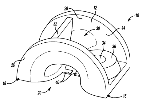
[0011] FIG. 1 is a perspective view of a cable guide according to the present
teachings;
[0012] FIG. 2 is a side view of the cable guide of FIG. 1;
2a
CA 02694077 2010-01-22
WO 2009/009051 PCTIUS2008/008389
[0013] FIG. 3 is a bottom view of the cable guide of FIG. 1;
[0014] FIG. 4 is top view of the cable guide of FIG. 1; and
[0015] FIG. 5 is a perspective view of the cable guide secured to an
exemplary mounting surface with a fastener and having a cable extending
through a securing portion in a secured position.
DETAILED DESCRIPTION OF VARIOUS EMBODIMENTS
[0016] Aspects of the present teachings may be further understood in
light of the following examples, which should not be construed as limiting the
scope of the present teachings in any way.
[0017] Turning now to the drawings, and initially to FIG. 1, a cable
guide is shown and generally identified at reference 10. The cable guide 10
generally includes a body 12 defining an intermediate portion 14 extending
between a first end 16 and a second end 18. The arcuate intermediate portion
14 can define a throat 20 for receiving a flexible member 25 (FIG. 5). The
arcuate intermediate portion 14 can generally define a first arched wall 26
and a
second arched wall 28 that connect through a generally parabolic central
portion
30. The first arched wall 26, the second arched wall 28, and the generally
parabolic central portion 30 collectively define a u-shaped cross-section of
the
cable guide 10. A transverse wall 32 can extend between the first and second
arched walls 26 and 28, respectively. A mounting aperture 34 can be defined
through a raised boss 36 formed on the first end 16. The mounting aperture 34
can receive a fastener 38 (FIG. 5) in a mounted position as will be described.
A
pair of fingers 40 can be formed on the body 12 at the first and second ends
16
and 18.
[0018] Turning now to FIG. 2, the first and second ends 16 and 18 can
terminate at generally planar end surfaces 42 and 44, respectively. The
transverse wall 32 can be generally perpendicular to the planar end surfaces
42
and 44. In one example, the fingers 40 can extend along the respective planar
end surfaces 42 and 44 in a direction toward the throat 20. The fingers 40 at
the
first and second ends 16 and 18 can facilitate retention of the flexible
member 25
(such as a cable, etc.) within the throat 20 if the cable guide 10 deflects or
the
3
CA 02694077 2010-01-22
WO 2009/009051 PCT/11JS2008/008389
fastener 38 is not completely tightened. The fingers 40 can be bendable or
pliable relative to the body 12. In one example, the fingers 40 may slightly
temporarily deflect to accommodate introduction of the flexible member 25 into
the throat 20.
[0019] With reference to FIG. 3, the cable guide 10 can define tabs 50
extending generally into the mounting aperture 34. The tabs 50 can assist in
holding the fastener 38 (FIG. 5) in place (i.e. relative to the body 12 in the
mounting aperture 34) while mounting the cable guide 10 to a surface.
[0020] Exemplary dimensions will now be described. The cable guide
10 can define a length L, a height H and a width W. In one example, the length
L can be 1.56 inches, the height H can be 0.84 inch and the width W can be
1.12
inches. It is appreciated that these dimensions are merely exemplary and may
vary according to application.
[0021] The cable guide 10 can be a unitary component (i.e. monolithic)
that can be formed of lightweight, low-friction, and wear-resistant material.
In
one example, the cable guide 10 can be formed of injection molded plastic such
as acetal resin engineering plastic. One exemplary material includes DeIrin
manufactured by DuPont.
[0022] With reference to FIG. 5, the cable guide 10 is shown mounted
to a mounting surface 52 with a flexible member 25 captured within the throat
20.
The smooth surface of the arcuate intermediate portion 14 of the cable guide
10
allows the use of cables that would normally fray if wrapped around objects
with
a smaller contact radius. The large radius contact surface can facilitate
cable
movement through the throat 20 (and discourage snagging) at any angle less
than 90 degrees relative to the mounting surface 52 while holding the flexible
member 25 close to the mounting surface 52.
[0023] One advantage of the cable guide 10 is that it can be installed
over a cable. Explained differently, a cable end need not be threaded through
the throat 20 as is required for other devices such as anchors (i.e., pulleys,
etc.).
In one exemplary method, the cable guide can be located adjacent to a cable
with the throat 20 generally aligned toward the cable. The planar end surfaces
42 and 44 can then be advanced toward the mounting surface 52 such that the
4
CA 02694077 2010-01-22
WO 2009/009051 PC T/US2008/008389
cable 25 locates through (between) the respective fingers 40. The fastener 38
can then be driven through the mounting aperture 34 to secure the cable guide
to the mounting surface 52.
[0024] While this disclosure has been described in connection with
5 particular examples thereof, the true scope of the disclosure should not be
so
limited. Furthermore, other modifications will become apparent to the skilled
practitioner upon a study of the drawings, the specification and the following
claims.
5