Note: Descriptions are shown in the official language in which they were submitted.
CA 02694637 2010-01-26
WO 2009/020556
PCT/US2008/009290
TITLE
ENDOLUMINAL PROSTHETIC CONDUIT
SYSTEMS AND METHOD OF COUPLING
FIELD OF THE INVENTION
The present invention relates to endoluminal prosthetic conduit
systems and in particular to methods and components for joining
together endoluminal prosthetic conduit components.
BACKGROUND OF THE INVENTION
Stents or stent grafts are forms of transluminal prosthetic
components which are used to maintain, open or dilate stenotic lesions
in body lumens or to cover and repair an aneurysm. It is often the case
that an aneurysm occurs at a branch or bifurcation in a vessel. To repair
such an aneurysm using modular components, one current technique is
to initially deploy across the aneurysm a main body stent or stent graft
having a side wall opening. The side wall opening is aligned with the side
branch ostium. A second stent or stent graft is then deployed through the
main body stent side wall opening and into the side branch vessel. This
modular repair approach requires the modular components to be
effectively sealed at their connection points to prevent blood leakage into
the aneurysm. In addition the modular components must be locked or
joined together to prevent subsequent relative displacement of the
modular components. Similar requirements apply to those procedures
that use multiple stent grafts that are coupled together to increase the
effective length of the repair device.
SUMMARY OF THE INVENTION
The present invention provides modular prosthetic conduit
systems such as stent or stent graft systems. The modular prosthetic
conduit systems may be tailored for the repair of aneurysms or for the
repair of compromised vessel walls. The systems incorporate various
1
CA 02694637 2010-01-26
WO 2009/020556
PCT/US2008/009290
embodiments for the secure interlocking of the multiple modular
components used in a vessel repair procedure.
An aspect of the invention includes a prosthetic conduit system
comprising: an expandable main conduit having a first open end, a
second open end, a main conduit wall extending therebetween, an outer
conduit surface, and an inner conduit surface having at least one
protuberance thereon; an expandable secondary conduit having a first
open end, a second open end, a secondary conduit wall extending
therebetween, and attachment portion extending at an angle of less than
90 degrees from the secondary conduit wall when in a deployed state;
and wherein at least a portion of the secondary conduit is sized to fit
inside the main conduit.
A further aspect of the invention includes a prosthetic conduit
system comprising: an expandable main conduit having a first open
end, a second open end, a main conduit wall extending therebetween, at
least one opening through the main conduit wall, and an internal channel
having an inner surface, an outer surface, a first open end located within
the main conduit and a second open end at the opening in the main
conduit wall; an expandable secondary conduit having a first open end, a
second open end, a secondary conduit wall extending therebetween,
and attachment portion extending at an angle of less than 90 degrees
from the secondary conduit wall when in a deployed state; and wherein
at least a portion of the secondary conduit is sized to fit inside the
internal channel and through the opening in the main conduit wall.
BRIEF DESCRIPTION OF THE DRAWINGS
Figure 1 is a side view of a main conduit with an interconnected
secondary conduit as implanted across an aortic aneurysm.
Figure 2 is a perspective view of a main conduit having an internal
protuberance.
Figure 3 is a cross-sectional view of a main conduit having an
internal protuberance.
Figure 4 is a perspective view of a main conduit joined to a
secondary conduit.
Figures 5A and 5B are perspective and side views of a secondary
conduit having an attachment portion. Shown is a defined angle between
2
CA 02694637 2010-01-26
WO 2009/020556
PCT/US2008/009290
an attachment portion and a secondary conduit longitudinal axis or
secondary conduit wall.
Figure 6 is a perspective view of a main conduit and an
interconnected secondary conduit.
Figure 7 is a cross-sectional view of a main conduit having an
internal protuberance that is discontinuous or segmented.
Figure 8 is a cross-sectional view of a main conduit having an
internal protuberance that incorporates stiffening support structures.
Figure 9 is a cross-sectional view of a main conduit having an
internal stent or support structure with barbs or hooks configured to
engage a secondary conduit.
Figures 10A and 10B are cross-sectional views of a main conduit
having internal barbs or internal hooks configured to engage a
secondary conduit.
Figures 11A and 11B are perspective views of a secondary
conduit having external barbs or external hooks configured to engage a
main conduit.
Figure 12 is a perspective view of a secondary conduit having an
external cuff that is configured to engage and lock onto an open end of a
support channel.
Figure 13 is a cross-sectional view of a main conduit having two
opposed cuffs.
Figure 14 is a side view of a secondary conduit having two
opposed cuffs.
Figures 15 A and 15B are side views of main conduits according
to certain aspects of the invention.
Figures 16 A and 16B are side views of main conduits and
secondary conduits according to certain aspects of the invention.
DETAILED DESCRIPTION OF THE INVENTION
A better understanding of the invention will be had with reference
to the several figures.
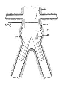
Shown in Figure 1 is a main conduit 20 having a first open end 22
and a second open end 24. A secondary conduit 26 is shown inserted
into the second open end 24 of the main conduit 20. The secondary
conduit 26 is shown as a bifurcated endoluminal device bridging an
3
CA 02694637 2010-01-26
WO 2009/020556
PCT/US2008/009290
aortic aneurysm 28. The main conduit 20 and the secondary conduit 26
are expanded and share an engagement portion or engagement length
30. In an aspect of the invention the main conduit 20 and the secondary
conduit 26 can be self-expanding or balloon expandable.
A main conduit can have various configurations including stent
grafts with or without side-branches or side-branch openings. Stent
grafts can be fabricated, for example, according to the methods and
materials as generally disclosed in US Patent Nos. 6,042,605;
6,361,637; and 6,520,986 all to Martin et al. Details relating to the
fabrication and materials used for a main conduit with an internal side
branch support tube or channel can be found in, for example, US Patent
No. 6,645,242 to Quinn.
The main conduit comprises at least one protuberance on the
inner surface of the main conduit. Protuberances according to an aspect
of the invention can be in many forms. For example, shown in Figure 2
is a perspective view of a main conduit 20 having a first open end 22 and
a second open end 24. Internal to the main conduit is protuberance in
the form of cuff 32 on the inner surface of the main conduit.
Figure 3 is a cross-sectional view of a main conduit 20 as viewed
along the cross-sectional plane 3 of Figure 2. Shown is a section of a
main conduit 20, first and second open ends 22, 24 and protuberance
32. The protuberance 32 is in the form of a cuff 34 that is configured to
engage an attachment portion of a secondary conduit. A protuberance or
cuff can have various configurations and can be fabricated, for example,
from tubes, sheets or films formed into tubular shapes, woven or knitted
fibers or ribbons or combinations thereof. Protuberance or cuff materials
can include conventional medical grade materials such as nylon,
polyester, polyethylene, polypropylene, polytetrafluoroethylene,
polyvinylchloride, polyurethane and elastomeric organosilicon polymers.
A protuberance or cuff can be joined to a graft or stent wall by sutures,
medical grade adhesives or thermoplastics or can be integral to the graft
or stent wall.
Shown in Figure 4 is a main conduit 20 having a first open end 22
and a second open end 24 and a wall 25 extending between the two
open ends. The wall defines an outer conduit surface 21 and an inner
conduit surface 23. A secondary conduit 26 is shown inserted into the
second open end 24 of the main conduit 20. The secondary conduit 26
4
CA 02694637 2011-12-16
WO 2009/020556
PCT/US2008/009290
has a first open end 27 a second open end 29 and a wall 31 extending
between the two open ends. The secondary conduit 26 has an
attachment portion 36 shown in a deployed state as flared apices of a
stent support structure. The attachment portion 36 is shown engaged
into the protuberance 32 of main conduit 20. The flared apices of the
stent support are therefore engaged and interlocked into the cuff 34,
preventing or inhibiting the secondary conduit 26 from dislodging toward
the direction indicated by arrow 38. An improved sealing surface
between the secondary and the main conduits may also be provided by
the protuberance 32. Forces exerted by the flow of blood may encourage
or drive the flared apices of the stent support into contact with or full
engagement with the cuff 34.
Shown in Figure 5A is a secondary conduit 26 having open ends
27 and 29, a wall 31 extending from open end 27 to open end 29, a
longitudinal axis 40 and attachment portion 36 shown in an
unconstrained or deployed state as flared-out apices of a support stent.
The inner surface 42 of the attachment portion 36 defines axis 44. An
angle 46 is shown between the secondary conduit longitudinal axis 40
(and the wall 31) and the attachment portion axis 44. Shown is an angle
of about 45 . Angle 46 can be any angle less than about 90 . For
example angle 46 can be just less than 90 , about 80 , about 70 , about
60 , about 45 , about 30 , about 20 or less.
Similar to Figure 5A, shown in Figure 5B is a secondary conduit
26 having open ends 27 and 29, a wall 31 extending from open end 27
to open end 29, a longitudinal axis 40 and an attachment portion 36
shown in a deployed state as flared-out apices of a support stent. The
inner surface 42 of the attachment portion 36 defines axis 44. An angle
46' is shown between the secondary conduit wall 31 and the attachment
portion axis 44. Shown is an angle of about 45 .
Various alternate configurations of attachment portions and/or
protuberances are possible. For example the protuberance 32 can be
discontinuous, forming discrete protuberance segments along the inner
wall of a main conduit. A main conduit can have two, three, four or five or
more discrete protuberance segments, spaced along the inner wall.
Shown in Figure 7 is a cross-sectional view of a main conduit 20 as
viewed along the cross-sectional plane 3 as defined in Figure 2. Shown
is a section of a main conduit 20, first and second open ends 22, 24 and
CA 02694637 2011-12-16
= .
WO 2009/020556
PCT/1JS2008/009290
discontinuous protuberances 34. The protuberances 34 form a series of
cuffs that are configured to engage attachment portions of a secondary
conduit, such as depicted in Figure 4.
To assist in the engagement of an attachment portion, a
protuberance can incorporate semi-rigid or densified segments along its
length. Such semi-rigid sections along a protuberance may prevent or
inhibit the protuberance from collapsing. Shown in Figure 8 is a cross-
sectional view of a main conduit 20 as viewed along the cross-sectional
plane 3 as defined in Figure 2. Shown is a section of a main conduit 20,
first and second open ends 22, 24 and a protuberance, shown as cuff
34. Densified or semi-rigid sections 62 are incorporated into the
protuberance to add rigidity to cuff 34 and thus inhibiting or even
preventing the cuff from collapsing. Semi-rigid sections 62 can be
incorporated into segmented or discontinuous protuberances as
previously described in Figure 7.
Semi-rigid or densified segments may be formed= from
conventional medical grade materials such as nylon, polyacrylamide,
polycarbonate, polyethylene, polyformaldehyde, polymethylmethacrylate,
polypropylene, polytetrafluoroethylene, polytrifluorochlorethylene,
polyvinylchloride, polyurethane, elastomeric organosilicon polymers;
metals such as stainless steels, cobalt-chromium alloys and nitinol and
biologically derived materials such as pericardium and collagen. Semi-
rigid or densified segments can also comprise bioresorbable materials
such as poly(amino acids), poly(anhydrides), poly(caprolactones),
poly(lactic/glycolic acid) polymers, poly(hydroxybutyrates) and
poly(orthoesters).
The at least one protuberance of the main conduit may comprise
an intemal stent or support structure that incorporates barbs, hooks or
other suitable configurations to engage and/or lock with a secondary
conduit. Shown in Figure 9 is a cross-sectional view of a main conduit 20
as viewed along the cross-sectional plane 3 of Figure 2. Shown is a
section of a main conduit 20, first and second open ends 22, 24 and an
intemal stent or support structure 64. Protruding out of the stent or
support structure 64 are a series of barbs or hooks 66. The barbs or
hooks are oriented inwards toward the center of the main conduit and
are configured to engage and/or lock onto a wall or attachment portion of
a secondary conduit.
6
CA 02694637 2011-12-16
WO 2009/020556
PCT/US2008/009290
A main conduit may have a series of internal, barbs or hooks that
are integral to the main conduit wall or integral to a main conduit support
stent. For example if the main conduit has a stent support structure,
portions of the stent can be formed into hooks or barbs that are
configured to engage and lock a secondary conduit. Shown in Figure 10A
is a cross-sectional view of a main conduit 20 as viewed along the cross-
sectional plane 3 of Figure 2. Shown is a section of a main conduit 20,
first and second open ends 22, 24 and a series of internal barbs 68.
Similarly shown in Figure 10B are a series of internal hooks 70. The barbs
or hooks are oriented inwards toward the center of the main conduit and
are configured to engage and/or lock onto an external wall of a
secondary conduit. Barbs or hooks may be formed from conventional
medical grade materials such as those listed above.
Secondary conduits can also incorporate various forms of
attachment portions to engage and/or lock onto main conduits. For
example shown in Figure 11A is a perspective view of a secondary
conduit 26 having first and second open ends 27, 29 and a wall 31.
Protruding outwardly away from the secondary conduit wall 31 are a
series of external barbs 72. Similarly, shown in Figure 11B are a series
of external hooks 74. The barbs or hooks are oriented outwardly away
from the center of the secondary conduit and are configured to engage
and lock onto an internal wall and/or protuberance of a main conduit.
A secondary conduit may also incorporate an external cuff that is
configured to engage a main body protuberance or an open end of an
internal channel. For example shown in Figure 12 is a perspective view
of a secondary conduit 26 having first and second open ends 27, 29 and
a wall 31. Formed about the first open end 27 is an external cuff 76
configured to engage an internal protuberance or a first open end of an
internal channel of a main conduit. The external cuff may incorporate
semi-rigid sections as shown in Figure 8 to add rigidity to the cuff.
=A main conduit may have opposed anchoring cuffs that prevent a
secondary conduit from being displaced in two directions. Shown in
Figure 13 is a cross-sectional view of a main conduit 20 having two
opposed engagement cuffs 78. The cuffs 78 are configured in a linear
state as shown in Figure 2 and Figure 3 . The cuffs 78 are configured to
engage attachment portions 36 of a secondary conduit 26. The
engagement of the attachment portions 36 to the cuffs 78 inhibit or
7
CA 02694637 2011-12-16
WO 2009/020556 PCT/US2008/009290
prevent dislodgement of the secondary conduit in the two directions
shown by arrows 38 and 80.
Secondary conduits can also incorporate attachment portions in
the form of bi-directional cuffs that inhibit or prevent dislodgement in two
directions. Shown in Figure 14, is a secondary conduit 26 having bi-
directional cuffs 82. The bi-directional cuffs 82 are configured to engage
opposed main conduit cuffs as shown in Figure 12.
In some surgical procedures it is desirable to have a side-
branched endovascular device, particularly for the repair of a vessel that
is in close proximity to branched vasculature.
Figure 6 is a perspective view of an alternate main conduit 50
having a first open end 22 and a second open end 24. Within the main
conduit 50 is an internal channel 54 having a first open end 56 and a
second open end 58 that is aligned to an opening 60 in the main conduit
wall 25. Such a main conduit can be fabricated according to the teaching
in U.S. Patent No. 6,645,242 to Quinn. A secondary conduit 26 having a
first open end 27, a second open end 29, a wall 31, and an attachment
portion 36 in a deployed state is shown inserted into the internal channel
54. The secondary conduit 26 is shown exiting out through the second
open end 58 of the internal channel 54 and through the opening 60 in
the main conduit wall. The attachment portion 36 is configured to engage
and/or interlock onto the first open end 56 of the internal channel. This
interlocking may prevent the dislodgement of the secondary conduit 26
along the direction depicted by arrow 38. Forces exerted by the flow of
blood may encourage or drive the attachment portion 36 into full contact
with the first open end 56 of the internal channel 54.
Stents can have various configurations as known in the art and
can be fabricated, for example, from cut tubes, wound wires (or ribbons)
or flat patterned sheets rolled into a tubular form. Stents can be formed
from metallic, polymeric or natural materials and can comprise
conventional medical grade materials such as nylon, polyacrylamide,
polycarbonate, polyethylene, polyformaldehyde, polymethylmethacrylate,
polypropylene, polytetrafluoroethylene, polytrifluorochlorethylene,
polyvinylchloride, polyurethane, elastomeric organosilicon polymers;
metals such as stainless steels, cobalt-chromium alloys and nitinol and
biologically derived materials such as bovine arteries/veins, pericardium
and collagen. Stents can also comprise bioresorbable materials such as
8
CA 02694637 2010-01-26
WO 2009/020556
PCT/US2008/009290
poly(amino acids), poly(anhydrides), poly(caprolactones),
poly(lactic/glycolic acid) polymers, poly(hydroxybutyrates) and
poly(orthoesters).
Grafts can have various configurations as known in the art and
can be fabricated, for example, from tubes, sheets or films formed into
tubular shapes, woven or knitted fibers or ribbons or combinations
thereof. Graft materials can include conventional medical grade
materials such as nylon, polyester, polyethylene, polypropylene,
polytetrafluoroethylene (including expanded polytetrafluoroethylene
("ePTFE")), polyvinylchloride, polyurethane and elastomeric
organosilicon polymers.
Stents can be used alone or in combination with graft materials.
Stents can be configured on the external or internal surface of a graft or
may be incorporated into the internal wall structure of a graft. Moreover,
main and secondary conduits can incorporate various stent or support
structures. For example as shown in Figure 15A, a main conduit 20 may
comprise separate stent segments 90A and 92A, positioned at or near
the first and second open ends 22 and 24 of the main conduit 20.
Similarly the stent segments 90A and 92A can comprise a single stent
94A extending from the first open end 22 to the second open end 24 of
the main conduit 20.
Shown in Figures 16A and 16B are secondary conduits 26
tailored to be inserted into main conduits 22 along direction arrows 96.
As shown in Figure 16A, a secondary conduit 26 can incorporate stents
90B and 92B at or near the first and second open ends 27 and 29 of the
secondary conduit 26. Similarly the stent segments 90B and 92B can
comprise a single stent 94B extending from the first open end 27 to the
second open end 29 of the secondary conduit 26.
Expandable conduits according to the invention can be delivered
in a constrained state endoluminally by various catheter based
procedures known in the art. For example self-expanding endoluminal
devices can be loaded onto the distal end of a catheter, compressed and
maintained in a constrained state by an external sheath. The sheath can
be folded to form a tube positioned external to the compressed device.
The sheath edges can be sewn together with a deployment cord that
forms a "chain stitch". Once the constrained device is positioned at a
target site within a vessel the device can be deployed. In the deployed
9
CA 02694637 2010-01-26
WO 2009/020556 PC
T/US2008/009290
state, the device may still be constrained by the vasculature or by
another device. For example a device may assume a diameter of 20mm
when fully un-constrained. This same device may be deployed into a
vessel (or other device) having a lumen diameter of 15mm and would
therefore be "constrained" in the deployed state. An "un-constrained
state" can therefore be defined as the state assumed by the device
when there are no external forces inhibiting the full expansion of the
device. A "constrained state" can therefore be defined as the state
assumed by the device in the presence of external forces that inhibit the
full expansion of the device. The deployed state can be defined as the
state assumed by the device when expanded into a vessel or other
device.
To release and deploy the constrained device, one end of the
deployment cord can be pulled to disrupt the chain stitch, allowing the
sheath edges to separate and release the constrained device.
Constraining sheaths and deployment cord stitching can be configured
to release a self-expanding device in several ways. For example a
constraining sheath may release a device starting from the proximal
device end, terminating at the distal device end. In other configurations
the device may be released starting from the distal end. Self expanding
devices may also be released from the device center as the sheath
disrupts towards the distal and proximal device ends. Details relating to
constraining sheath materials, sheath methods of manufacture and main
body compression techniques can be found in US Patent No. 6,352,561
to Leopold et al., and US Patent No. 6,551,350 Thornton et al.
In the deployment of a secondary conduit for example, the
secondary conduit can be released from a constraining sheath starting at
the proximal (or hub) end of the constrained conduit. In typical
procedures, the attachment portion of the secondary conduit is located
about the proximal end of the conduit and in an aspect of the invention
this proximal end is the first end released from a constraining sheath,
thus also deploying the attachment portion.
While particular embodiments of the present invention have been
illustrated and described above, the present invention should not be
limited to such particular illustrations and descriptions. It should be
apparent that changes and modifications may be incorporated and
CA 02694637 2011-12-16
=
WO 2009/020556
PCT/US2008/009290
embodied as part of the present invention.
11