Note: Descriptions are shown in the official language in which they were submitted.
CA 02694764 2010-02-25
1 "SOLAR HEATING SYSTEM WITH OVERHEATING PROTECTION"
2
3 FIELD OF THE INVENTION
4 Embodiments of the invention relate to solar heating systems
and
more particularly to systems for use with solar water heaters that are
independent of
6 the electrical utility grid and that substantially prevent overheating of
fluids
7 circulating therethrough.
8
9 BACKGROUND OF THE INVENTION
Collection of solar energy for use in heating fluids, such as water, is a
11 well known concept with rudimentary systems originating in ancient
times. Modern
= 12 solar heating systems typically incorporate a solar
collector that converts the sun's
13 energy to thermal energy and utilize a variety of means to transfer the
collected
14 thermal energy into the fluid to be heated, such as for residential,
commercial or
industrial heating applications.
16 Solar water heaters may be combined systems or distributed
systems.
17 In the case of a combined system, a domestic water storage tank is
typically
18 mounted directly to the solar collector. Combined systems are generally not
19 practical in colder climates as the hot water storage tank is cooled by
the cold
ambient air. In the case of a distributed system, the solar collector is
typically
21 located remote from the heated water storage tank, the storage tank
being placed in
22 a sheltered location to avoid heat loss to the atmosphere. Distributed
solar water
23 heaters are common.
1
CA 02694764 2010-02-25
1
"Direct" solar water heater systems circulate the domestic water to be
2 heated
through the solar collector. Direct systems are typically prone to scaling of
3 the
collector as a result of the domestic water passing therethrough. Further,
direct
4 systems
require the collector to be drained when ambient temperatures fall below
the freezing point of water (0 C). Direct systems can be configured as either
6 combined systems or distributed systems.
7 More
sophisticated distributed systems known as "indirect" heating
8 systems
circulate a heat transfer fluid or working fluid between the solar collector
9 and a
potable water heat exchanger which transfers the solar heat from the working
fluid into the potable water. The heat exchanger, such as a tubular coil, may
be
11 placed
inside a potable water tank for transferring heat from the working fluid
12
circulating through the coil to the water in the tank. Alternatively, the heat
exchanger
13 can be
located external to the potable water tank, the potable water circulating on
14 one
side of the heat exchanger and the working fluid on the other side. Indirect
systems typically use a working fluid that comprises agents to reduce scaling
and
16 an anti-freeze agent to avoid freezing of the working fluid.
17 Solar
energy can only be harnessed when the sun is shining and
18 some of
the heat gained during the day is lost if the potable water or working fluid
19
continues to circulate during nights or during periods of low solar potential.
Consequently conventional solar systems require a means for stopping
circulation
21 of the
working fluid during non-heating conditions. Some systems use a "drain-back"
22
approach that drains the working fluid into a holding tank during the non-
heating
2
CA 02694764 2010-02-25
1 periods. Systems that don't "drain-back" require enough anti-freeze agent
to ensure
2 the working fluid does not freeze up and damage the piping or solar
collector.
3 A significant issue with solar water heating systems is how to
mitigate
4 excessive heat. During periods when solar heating of the potable water
exceeds
the demand for heated potable water, heat will build up in the system. If
means for
6 releasing pressure are not provided, excess heat leads to boiling of the
working fluid
7 and the resultant pressure increases will rupture the piping or solar
collector.
8 Conventionally, overheating is addressed using a number of different
mechanisms.
9 "Heat dumps" dissipate excess heat to the atmosphere or through a ground
loop or
other location. Alternatively, the system is drained back and shut down or the
11 system controller can be manually set to a "vacation" setting that
diverts the heat
12 from the potable water system.
13 Often systems are deliberately under-sized to avoid the overheating
14 challenge. In this case, the solar collector system is sized such that
its peak output
will provide 90% of the minimum anticipated heat load. As the output of the
solar
16 collectors is seasonally dependent, this approach usually results in the
solar water
17 heating system contributing about half of the water heating requirement,
the
18 remainder being provided through conventional non-solar water heating
systems
19 and requiring a reliance on the electric utility grid or other external
energy provider.
Thus, it is clear in these cases that solar collection is not maximized.
21 Canadian Patent 1,080,566 to Cummings teaches a solar water
22 heater incorporating a heat rejecting loop to attempt to cool the
system. The system
23 is complex and incorporates two separate fluid circuits; one comprising
a heat
3
CA 02694764 2010-02-25
1
absorbing loop fluidly connected to a heat rejecting loop and the second
comprising
2 a heat pickup loop thermally coupled to the solar panel to carry thermal
energy
3 away
from the panel to the point of use. Circulation of fluid through at least the
heat
4 absorbing and heat rejecting loops is solely by gravity and thermal
convective
effects.
6 EP
04727915 to Torrens teaches a complex solar collection system in
7 series
with a hot water system. A heat dissipater circuit, which may comprise at
8 least
part of the panel framework, is used for cooling at least a portion of hot
water
9 exiting
the solar panels when the water is overheated. The inlet to the heat
dissipater is downstream from the solar panels and thus all of the fluid must
first be
11 heated
and then at least a portion cooled for cooling the system. Torrens relies
12 upon
thermosiphon effects in the event of pump failure to ensure all of the water
in
13 the
system is directed through the heat dissipater to prevent overheating.
Applicant
14
believes it is likely that there will be insufficient impetus for thermosiphon
within the
complex piping of Torrens, resulting in the possibility of overheating of the
fluids
16 therein
despite the heat dissipation circuit. The Torrens system is particularly
17
unsuitable for use where ambient temperatures fall below freezing as it is a
direct
18 system.
19 Apricus
Solar Co. Ltd. (www.apricus.com/html/solar_heat_dissipator.htm)
teaches a solar hot water system comprising a fin and tube heat dissipater
21
connected downstream from solar collectors. The system as described utilizes
an
22
electrically powered controller and a solenoid valve operated by the
controller, to
23 direct
overheated fluid from the solar collectors to the heat dissipater.
Alternatively,
4
CA 02694764 2010-02-25
1 it is mentioned that a thermostatic valve may be used. All of the fluid
in the heat
2 transfer circuit is first heated in the solar collector after which at
least a portion of
3 the fluid is directed to the heat dissipater for cooling after which the
cooled fluid is
4 mixed into the stream of overheated fluid. In cases of peak insolation,
sufficient heat
may not be released by the heat dissipater. Following heat dissipation, the
6 temperature of the re-mixed working fluid may be inconsistent as the
efficiency of
7 the heat dissipater varies with atmospheric conditions. If excessive heat
dissipation
8 occurs the efficiency of the system is reduced. If insufficient heat
dissipation occurs
9 there remains a risk that the system will over-heat.
Current indirect-distributed systems typically utilize electronic control
11 systems to activate pumps and valves to operate the system. The
electronic
12 controller utilizes preprogrammed logic to operate the valves and pumps as
13 conditions determine when to circulate fluid to the solar collector,
when to drain-
14 back or load the working fluid, if applicable, when to circulate through
an external
heat exchanger and when to activate systems which handle excess heat, if
16 available. The operating conditions are measured by electronic
temperature and
17 pressure sensors which are connected electrically to the electronic
controller. Thus,
18 these control and operating systems require electrical energy which is
usually
19 supplied from the electric utility grid. Loss of electrical energy will,
at a minimum,
cause loss of solar heating. It can also potentially cause damage to the
system
21 should the system overheat, result in injuries such as scalding and
result in
22 collateral damage to the building such as stained walls and floors
caused by
23 overflow of working fluid from ruptured lines and the like.
5
CA 02694764 2010-02-25
1 In order to deal with these problems, some systems provide a
battery
2 backup to enable the system and controller to operate for a period of
time when the
3 power goes out. In some cases, solar photovoltaic (PV) systems are
available to
4 supply the necessary electrical energy either directly to the solar
heating system
and controller or indirectly, such as through a battery pack.
6 In addition to requiring electrical energy to operate the solar
heating
7 system, electronic control methods are prone to component failure
especially when
8 considered in the context of the twenty-year life of a typical solar
water heating
9 system. Failure of the electronic control system can lead to piping or
component
damage and collateral damage similar to that which occurs with the loss of
electrical
11 energy. Battery systems also have a shorter life expectancy, usually in
the five to
12 ten year range. Failure to test and replace the battery system can lead
to same
13 type of damage seen with loss of electrical energy.
14 Ideally, what is required is a solar water heater system that is
simple,
efficient and requires no reliance on the electric utility grid or other
external energy
16 provider. The solar water heater system should be capable of meeting
maximum
17 demand during periods of low insolation without concern of overheating
and the
18 resulting potential damage to the systems and structures during periods
of high
19 insolation, and particularly during periods where there is also a low
demand.
6
CA 02694764 2010-02-25
1 SUMMARY OF THE INVENTION
2 A self-
controlled solar heating system and method of use is
3
independent of the electrical utility grid or external energy provider and
operates
4
substantially without risk of overheating during periods of maximum
insolation,
despite being sized for maximum solar energy absorption. When the temperature
or
6 pressure of a fluid in the heat exchange circuit exceeds a preset operating
7
maximum, some of the fluid is caused to automatically bypass the solar
collectors to
8 enter a
heat dissipater. Fluid in the system is pumped at a rate relative to the
9 amount of solar energy available using a solar powered pump.
In one broad aspect of the invention, apparatus for maximizing
11 thermal
energy collection in a solar collection system independent from the electric
12 utility
grid or external energy provider comprises: one or more solar collectors; a
13 heat
exchange circuit having fluid therein and being thermally connected between
14 the one
or more solar collectors and a point of use; a solar powered pump for
substantially continuously pumping the fluid through the heat exchange circuit
16 during
solar energy collection; a heat dissipater fluidly connected to the heat
17
exchange circuit and having an inlet upstream from the one or more solar
collectors
18 and an
outlet downstream from the one or more solar collectors; and a valve
19
positioned downstream from the heat dissipater which, when closed in response
to
a condition being at or below a maximum preset operating condition, prevents
fluid
21 from
entering the heat dissipater; and when opened in response to the condition
22
exceeding the maximum preset operating condition, permits at least a portion
of the
23 fluid
in the heat exchange circuit to bypass the one or more solar collectors to
flow
7
CA 02694764 2010-02-25
1 through the heat dissipater for cooling the at least a portion of the
fluid, the cooled
2 fluid being returned to the heat exchange circuit thereafter through the
outlet for
3 maintaining the working fluid at or below the maximum preset operating
condition.
4 In another broad aspect of the invention, a method for maximizing
thermal energy collection in a solar collection system independent from the
electric
6 utility grid or external energy provider comprising one or more solar
collectors, and
7 a heat exchange circuit having fluid therein, the heat exchange circuit
being
8 thermally connected between the one or more solar collectors and a point
of use,
9 the method comprising: continuously pumping fluid through the heat
exchange
circuit and the one or more solar collectors during solar energy collection
using a
11 solar-powered pump to heat the fluid and when a condition of the heated
fluid
12 exceeds a maximum preset operating condition; bypassing at least a
portion of the
13 continuously pumped fluid around the one or more solar collectors
through a heat
14 dissipater for producing a cooled fluid; and recombining the cooled
fluid with the
heated fluid in the heat exchange circuit downstream from the solar collector
for
16 cooling the heated fluid for maintaining the working fluid at or below
the maximum
17 preset operating condition.
18 In embodiments of the invention, the valve which opens to flow
fluid to
19 the heat dissipater and bypass the solar collectors is actuated by
either temperature
or pressure.
21 In embodiments of the invention the system can be either an
indirect
22 system, wherein the working fluid flowing through the heat exchange
circuit is a fluid
23 such as glycol, or a direct system wherein the fluid which is circulated
through the
8
CA 02694764 2015-02-19
1 heat
exchange circuit is the fluid to be used at the point of use, such as potable
2 water.
3
4 BRIEF DESCRIPTION OF THE DRAWINGS
Figures 1A-1D are schematics illustrating flow paths of some prior art,
6 more complex, solar heater systems;
7 Figure
2A is a schematic illustrating a solar water heater system
8 according to an embodiment of the invention;
9 Figure
2B is a schematic illustrating flow paths in the solar water
heater system of Fig. 2A;
11 Figure
3 is a schematic illustrating flow of working fluid through the
12 solar water heater system of Fig. 2A, during a normal heating cycle;
13 Figure
4 is a schematic illustrating flow of working fluid through the
14 solar
water heater system of Fig. 2A, at a maximum operating condition of the
working fluid in the system; and
16 Figure
5 is a graphical representation of working fluid temperature in
17 degrees
Centigrade, BTU's generated and BTU's dissipated using an embodiment
18 of the
invention and monitored through a mid-day period where solar energy is at a
19 maximum.
21
9
CA 02694764 2015-02-19
1 DETAILED DESCRIPTION OF THE PREFERRED EMBODIMENT
2 Embodiments of the invention comprise self-controlling solar
heating
3 systems having one or more solar collectors, an excess heat dissipater,
and an
4 elegant yet simple heat transfer circuit fluidly connected between the
solar
collectors and a point of use. A variable speed direct current (DC) pump
circulates
6 fluid through the heat transfer circuit, powered by a photovoltaic panel
so as to
7 remove any reliance upon an external energy provider. The pumping rate of
the
8 fluid is self-controlling and relative to the amount of solar energy
available.
9 The heat dissipater is fluidly connected around the solar
collectors.
Without a need for a sophisticated controller, upon overheating, a valve
directs at
11 least a portion of the fluid to flow through the heat dissipater for
bypassing the solar
12 collectors and cooling the fluid. The valve opens when the fluid exceeds
a present
13 threshold condition in the fluid which is indicative of overheating. The
valve is
14 positioned in the heat transfer circuit downstream from both the solar
collectors and
the heat dissipater. As the valve opens, at least a portion of the fluid
bypasses the
16 solar collector, fluid flowing both through the heat dissipater and the
solar collectors.
17 Cooled fluid from the heat dissipater mixes with heated fluid exiting
the solar
18 collectors for maintaining the working fluid below the preset threshold
operating
19 condition, being either temperature or pressure.
As atmospheric conditions vary, the valve modulates between open
21 and closed so to alter the rate of fluid flowing through the heat
dissipater. Thus the
22 system automatically and efficiently maintains the working fluid at as
close to the
23 maximum operating conditions without exceeding the preset threshold.
CA 02694764 2010-02-25
1 In order to understand the simplicity and the reliability of the
2 overheating protection accomplished without reliance upon the electric
utility grid or
3 external energy provider and according to embodiments of the invention,
it is first
4 necessary to understand the flow paths of some complex prior art systems
which
also employ heat dissipaters.
6
7 Prior art systems
8 As shown in simplified schematic Fig. 1A, Canadian Patent
1,080,566
9 to Cummings teaches two separate fluid circuits. A first circuit 10
within a solar
panel 12 comprises both a heat absorbing loop 14 and a heat dissipating loop
16. A
11 second circuit or heat-pickup loop 18 picks up heat within the panel 12
and
12 circulates fluid therein outside the solar panel 12 to a point of use
20, typically a
13 heat exchanger in a water tank. A thermally actuated valve 22 is
positioned
14 between the heat-absorbing loop 14 and the heat-dissipating loop 16.
When the
temperature in the heat-absorbing loop exceeds a preset threshold, the valve
22
16 opens for directing the fluid to the heat-dissipating loop 16. The
system relies solely
17 upon differential buoyancy and thermosiphon effects to circulate fluid
through at
18 least the first circuit 10. Applicant believes that the heat-dissipating
loop 16 acts to
19 cool the solar panel 12, but is less effective in cooling the working
fluid. Further
Applicant believes that there are potential efficiency losses if the heat-
pickup loop
21 18 loses heat to the first circuit 10.
22 Simplified schematics, Figs 1B and 1C, illustrate two embodiments
23 taught by EP04727915 to Torrens. Torrens utilizes a heat exchange
circuit 30 to
11
CA 02694764 2010-02-25
1 circulate water through a series of solar panels 12. In a first
embodiment (Fig. 1 B) a
2 thermostatic T-valve 32 is positioned downstream from the solar panels 12
and
3 upstream from a heat dissipater 34. In this embodiment, all of the fluid
in the heat
4 transfer circuit must pass through the solar panels 12 and be heated
therein.
Thereafter, a portion of the flow is directed to the heat dissipater 34 for
cooling
6 therein. Torrens employs a check valve 36 between the heat dissipater 34
and the
7 heat exchange circuit 30. Torrens states that the check valve 36 is designed
to
8 ensure fluids exiting the heat dissipater 34 return to the heat exchanger
circuit 30
9 upstream from a point of use 38 for cooling the fluid therein, when a
pump 40 which
circulates fluid in the heat exchange circuit 30 is functioning. Applicant
believes it
11 likely that there is more resistance to flow through the heating load
and therefore,
12 unless a very high resistance check valve is used, fluids are likely to
bypass the
13 heating load through the check valve. In this case there is reduced flow
of fluids
14 though the heating load reducing the energy available to the working load
and
ultimately reducing the efficiency of the overall system.
16 Torrens also illustrates that in the event of a pump failure or
loss of
17 electricity, hot fluid exiting the solar panel is directed by
thermosiphon through the
18 check valve 36 and back to the series of solar panels 12, bypassing the
point of use
19 38. If a high resistance check valve 36 is used to prevent bypass of the
heating load
in regular use, it is more unlikely that there would be significant impetus
for fluids to
21 flow through the check valve 36 by thermosiphon in the event that the
pump 40 or
22 the electricity fails.
12
CA 02694764 2010-02-25
1 In an alternate embodiment (Fig. 1C), where the heat dissipater 34
is
2 part of the solar panel framework, Torrens does not use a check valve 36
but
3 instead separates a first solar collector 12' from the remaining solar
collectors 12
4 using a thermostatic valve 32 and in the event of a need to cool water
exiting the
remaining solar collectors 12, passes water through the heat dissipater 34 for
6 recycling through the remaining solar collectors 12. Applicant assumes
that in the
7 event of a pump failure, maintaining the first solar panel 12' cooler
than the
8 remaining solar panels 12 permits some thermosiphon effect, however it is
unclear
9 if the system would operate as described.
As illustrated in Fig. 1D, Apricus Solar Co. Ltd., teaches a system
11 having solar panels 12 and a heat exchange circuit 50, incorporating a
fin and tube
12 heat dissipater 52 connected downstream from the solar collectors 12. An
13 electrically powered controller and a solenoid valve, operated by the
controller,
14 direct overheated fluid from the solar collectors 12 to the heat
dissipater 52.
Alternatively, it is mentioned that a thermostatic valve 54 may be used. All
of the
16 fluid in the heat transfer circuit 50 is first heated in the solar
collectors 12 after which
17 at least a portion of the fluid is directed to the heat dissipater 52
for cooling after
18 which the cooled fluid is mixed into overheated fluid in the heat
exchange circuit 50
19 for cooling the fluid therein.
21 Embodiments of the invention
22 Embodiments of the invention are described herein in the context
of a
23 domestic hot water heater. As those of skill in the art will appreciate
however, the
13
CA 02694764 2015-02-19
1 system as described can be used to collect solar energy for a variety of
purposes
2 and therefore the system is not limited solely for use as a water heater
for domestic
3 hot water use. Other uses may include pool heating, space heating via
hydronics,
4 forced-air, radiant or other fluid-based space heating processes, process
water or
fluid heating for industrial, refining, processing, smelting or commercial
operations;
6 heating of cleaning water for commercial laundries, car washes or similar
uses; or
7 any other heating or pre-heating application, either directly or
indirectly from the
8 solar heated fluid.
9 In an embodiment of the invention, as shown in Figs. 2A, 2B, 3 and
4,
the solar water heater system 110 comprises one or more solar collectors 112,
such
11 as evacuated-tube heat-pipe collectors, flat plate solar collectors or
any other type
12 of solar thermal collector or panel, for absorbing solar energy from the
sun.
13 A heat transfer or exchange circuit 114 is connected for
circulating a
14 working fluid between the solar collectors 112 and a point of use 115.
The solar
water heater system 110 can be either an indirect system or a direct system.
16 Embodiments of the solar heater system 110, whether direct or
17 indirect, further comprise a heat dissipater 120 which is connected to
the heat
18 exchange circuit 114. The heat dissipater 120 forms a bypass around the
solar
19 collectors 112, connected at an inlet upstream of the solar collectors
112 and
connected at an outlet downstream thereof. The heat dissipater permits at
least a
21 portion of the circulating fluid in the heat exchange circuit 114 to
bypass the solar
22 collectors 112 when a condition of the fluid related to overheating
exceeds a
14
CA 02694764 2010-02-25
1 preset
threshold. The flow of fluid to the heat dissipater is modulated to maintain
2 the condition of the fluid at or below the maximum preset condition.
3 In
embodiments of the invention, the condition of the fluid is generally
4 either the temperature of the fluid or the pressure of the fluid.
In embodiments of the invention, the solar collectors 112 are sized to
6 absorb
the maximum solar energy available and the heat dissipater 120 is sized
7 accordingly.
8 The
system 110 is further described herein in the context of an indirect
9 system
using temperature as the condition indicative of overheating. Those of skill
in the art would appreciate however that the description is equally applicable
in the
11 case of
a direct system or where pressure is the condition of the fluid indicative of
12 overheating.
13
Accordingly, using temperature as the condition, a thermally-actuated
14 control
valve 124 is positioned in the heat exchange circuit 114 downstream from
the solar collectors 112. In one embodiment, the valve 124 is located at the
16
conjunction of the heat dissipater 120 and the solar collectors 112. As shown,
the
17 valve
124 can be a three-way valve, receiving fluid from the solar collector or both
18 the
heat dissipater and the solar collectors for discharge back to the heat
exchange
19 circuit 114.
If the temperature of the working fluid exiting the solar collectors 112
21 reaches
a preset threshold, the valve 124 opens to fluidly connect with the heat
22
dissipater 120 to permit at least a portion of the circulating working fluid
to exit the
23 heat
dissipater 120. Accordingly, at least a portion of the fluid which would
CA 02694764 2010-02-25
1 otherwise enter the solar collectors 112 instead enters the heat
dissipater 120 for
2 producing a cooled fluid. The cooled fluid is thereafter mixed with the
heated fluid
3 exiting the solar collectors 112. When the temperature of the working
fluid is below
4 the preset threshold or maximum preset operating temperature, such as when
sufficient heat has been utilized at the point of use 115 or has been
dissipated from
6 the working fluid, the valve 124 closes to again direct the entirety of
the flow of
7 working fluid through the solar collectors 112. The valve 124 modulates
between
8 open and closed. As previously noted, changes in atmospheric conditions
can alter
9 heat dissipation from the heat dissipater 120. As the temperature of the
heated
working fluid changes in response to changes in heat dissipation, the flow of
fluid
11 entering the heat dissipater 120 is automatically changed or modulated
by the
12 thermally-actuated control valve 124 so as to maintain the temperature of
the
13 working fluid at the maximum preset operating temperature.
14 Thus, as shown in Fig. 3, in normal operation, when the
temperature
of the working fluid exiting the solar collectors is below the maximum preset
16 operating temperature, the thermally-actuated control valve 124 remains
closed and
17 none of the working fluid is circulated through the heat dissipater. The
temperature
18 of the working fluid is substantially continuously monitored by the
thermally actuated
19 control valve 124.
As shown in Fig. 4, when the temperature in the working fluid
21 approaches the preset maximum operating temperature, the valve 124
begins to
22 open, permitting at least a portion of the fluid to pass through the
heat dissipater
23 120 to be cooled. The cooler fluid exits the heat dissipater 120 and
mixes or
16
CA 02694764 2015-02-19
1 recombines with the heated working fluid exiting the solar collectors 112
to maintain
2 the temperature of the working fluid in the heat exchange circuit 114 at
the preset
3 maximum operating temperature. In order to permit maximum solar energy
4 absorption by the solar collectors 120 without risk of overheating, the
valve 124 is
capable of opening fully to split the flow of working fluid between the solar
collectors
6 112 and the heat dissipater 120. With the valve 124 fully open, the heat
gain by the
7 solar collectors 112 is balanced with the heat loss from the heat
dissipater for
8 maintaining the temperature of the working fluid at about or below the
preset
9 maximum operating temperature.
In embodiments of the invention, the heat dissipater 120 comprises a
11 fin and tube radiator for exchanging heat from the working fluid to the
atmosphere.
12 Alternatively, the heat dissipater 120 could comprise a flat plate
radiator, a ground
13 loop or other type of heat sink to absorb the excess heat from the
working fluid.
14 With reference again to Fig. 4, during periods of high solar
energy or
insolation, such as midday and when the working fluid temperature approaches
the
16 preset maximum temperature, in this case 90 C, the thermally-actuated
control
17 valve 124 opens to bypass a slipstream of fluid through the heat
dissipater and
18 remove heat from the working fluid. Fig. 5 represents a test of solar
collectors, a fin
19 and tube radiator for dissipating heat and a thermally-actuated control
valve. There
was no heating load on the system.
21 The heat exchange circuit 114 further comprises a variable speed
DC
22 pump 130 for pumping fluids through the heat exchange circuit 114. In
order to
23 remove any reliance upon the electric utility grid, the pump 130 is
powered by a
17
CA 02694764 2010-02-25
1 photovoltaic (PV) array or panel 132. The PV panel 132 may be integrated
with the
2 solar collectors 112 or may be remote from the solar collectors 112. Use
of the PV
3 panel 132 to create solar electricity causes the variable speed DC pump 130
to
4 circulate the working fluid proportionately to the solar conditions. In
other words,
when solar energy or insolation is at a maximum, the pump circulates fluid
more
6 quickly through the heat exchange circuit 114 and, when solar energy is
very low or
7 not available, such as at night or in other low light conditions, the
pumping slows or
8 stops, effectively shutting down the system 110.
9 The heat exchange circuit 114 further comprises an expansion tank
140 to accommodate increases in volume of the working fluid with increased
11 temperature. A pressure relief valve (PRV) 142 is incorporated for
releasing
12 working fluid from the heat exchange circuit 114 in the event of a
failure of the
13 thermally-actuated control valve 124, the pump 130 or a vapor lock
within the
14 system 110. Should the pressure in the heat exchange circuit 114 exceed
a preset
pressure, generally as a result of expansion beyond the capacity of the
circuit 114,
16 including the expansion tank 140, the PRV 142 opens and the working
fluid is
17 discharged. Such conditions can occur if the working fluid begins to
vaporize.
18 To avoid collateral damage, the environmentally-friendly working
fluid
19 is discharged such as onto the roof or through conduits (not shown)
which direct the
working fluid away from structures which may be damaged thereby.
21 As shown in Fig. 2A, and in embodiments where the system is an
22 indirect system, the heat transfer or exchange circuit 114 is connected
between the
23 solar collectors 112 and a heat exchanger 116 which is typically at the
point of use
18
CA 02694764 2010-02-25
1 115. A working fluid, such as glycol, circulates through the exchange
circuit 114. In
2 the case of a water heater, the heat exchanger 116 is typically internal
to a hot
3 water tank 118 for exchanging heat between the working fluid and potable
water
4 contained in the hot water tank 118. Alternatively, the heat exchanger
116 can be
external to the hot water tank 118. When intended for use in climates where
6 ambient temperatures are low, such as in northern climates where
temperatures
7 may be below freezing, the working fluid comprises suitable amounts of
antifreeze.
8 In embodiments where the system is a direct system, the heat
transfer
9 circuit 114 is fluidly connected to the hot water tank 118 and potable
water from the
tank is the working fluid being circulated through the heat transfer circuit
114. Direct
11 systems may be limited for use in climates where the temperature remains
above
12 freezing as antifreeze cannot be mixed with the potable water flowing
therethrough.
13
14
19
CA 02694764 2010-02-25
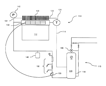
1 Example
2 In an indirect solar water heater system, according to an
embodiment
3 of the invention and as shown schematically in Fig. 2A, a solar collector
112
4 comprising 30, 58mm x 1800mm evacuated tubes, rated at a maximum thermal
output of about 7400 BTU per hour, available from Jiangsu Sunrain Co. Ltd.,
was
6 mounted to the roof of a structure. The collector assembly was mounted at
an angle
7 of about 70 degrees from horizontal to ensure solar gain was maximized
during the
8 winter and minimized during the summer as is known in the art.
9 The solar collector 112 was thermally and fluidly connected to a
300L
(80 USG) hot water tank 118 located within the structure, using 3/4" cross-
linked
11 polyethylene (PEX) pipe and fittings, for forming the heat exchange
circuit 114,
12 through which a working fluid was circulated. All piping in the system
was insulated
13 to reduce energy losses.
14 The working fluid for circulation through the heat exchange
circuit
comprised distilled water mixed at about 50% with non-toxic propylene glycol
to
16 ensure the fluid would not freeze at -40 C temperatures. An expansion
tank 140,
17 having a volume sufficient to contain about 2.5% of the volume of the
fluid at 20 C,
18 was fluidly connected to the heat exchange circuit 114. The pressure
within the heat
19 exchange circuit 114 was maintained at a lower pressure than that in the
hot water
tank 118 to avoid glycol from entering the domestic hot water system in the
event of
21 a leak in the internal heat exchanger 116.
CA 02694764 2010-02-25
1 Fill
and drain valves 150 were incorporated into the heat exchange
2 circuit
114 to facilitate loading the circuit 114 and to permit periodically checking
the
3 pH and strength of the glycol/water mixture.
4 A
pressure relief valve (PRV) 142 having a preset threshold of about
50 psi was connected to the heat exchange circuit 114. Should the pressure
within
6 the
circuit 114 exceed the preset threshold, for example as a result of a failure
in the
7 system,
the PRV 142 would open and the working fluid would be released to the
8 roof of the structure.
9 An 8
foot length of fin and tube radiator 120, sized to exceed the
maximum BTU rating of solar collector 112 by about 5% or about 40 BTU per
hour,
11 was
connected to the heat exchange circuit 114 to bypass the solar collector 112.
12 An
inlet 121 to the radiator 120 was upstream from the solar collector 112 and an
13 outlet 122 from the radiator 120 was downstream from the solar collector
1'12.
14 A
bimetallic thermal by-pass valve 124, available from Caleffi
Hydronics Solutions (Part #309460) was connected to the heat exchange circuit
114
16
downstream from the solar collector 112 and the heat dissipater 120. The
preset
17 maximum
operating temperature of the valve was 90 C (200 F) for diverting flow
18 from
the heat exchange circuit 114 to the inlet 121 of the heat dissipater 120 and
19
bypassing the solar collector 112 if the temperature in the working fluid
exceeded
90 C.
21 A
variable DC Pump 130, such as a 12 VDC, 20 watt, 8 liter/min
22 pump,
such as an El CID pump available from Ivan Labs Inc. or an Ecocirc pump
23
available from Laing Thermotech, Inc., was used to pump the working fluid
through
21
CA 02694764 2010-02-25
1 the heat exchange circuit 114. The pump 130 was powered by a 25 watt
2 photovoltaic panel available from Fuzhou Pingchi Import & Trading Co of
China.
3 An anti-scald valve 160, such as a Danfoss ESSBE 06568870 valve
4 available from Danfoss Hydronic Heating North America, was placed on an
outlet of
the hot water tank 118 to act as a safety device for ensuring water exiting
the tank
6 118 would not exceed a safe temperature, in this case from about 50 C
(122 F) to
7 about 60 C (140 F) where higher temperatures are required for appliances
such as
8 dishwashers and clothes washer.
9
22