Note: Descriptions are shown in the official language in which they were submitted.
CA 02694896 2010-01-28
WO 2009/016139 PCT/EP2008/059843
- 1 -
PROCESS FOR PRODUCING PURIFIED GAS FROM GAS COMPRISING
H2S, CO2 AND HCN AND/OR COS
The invention relates to a process for producing
purified gas from gas comprising hydrogen sulphide (H2S),
carbon dioxide (C02) and hydrogen cyanide (HCN) and/or
carbonyl disulphide (COS).
The gas can be natural gas, synthesis gas or a gas
effluent.
Synthesis gas mainly comprises carbon monoxide and
hydrogen. Syntesis gas is generally produced via partial
oxidation or steam reforming of hydrocarbons including
natural gas, coal bed methane, distillate oils and
residual oil, and by gasification of solid fossil fuels
such as coal or coke. Reference is made to Maarten van
der Burgt et al., in "The Shell Middle Distillate
Synthesis Process, Petroleum Review Apr. 1990 pp. 204-
209" for a general description on the preparation of gas.
Depending on the feedstock used to generate synthesis
gas, the gas will contain contaminants such as carbon
dioxide, hydrogen sulphide, carbonyl sulphide and
carbonyl disulphide while also nitrogen, nitrogen-
containing components, e.g. HCN and NH3 and metal
carbonyls may be present.
Numerous natural gas wells produce what is called
"sour gas", i.e. natural gas comprising acidic compounds
such as carbon dioxide and/or sulphur compounds such as
H2S, sulphides, disulphides and thiophenes. The total
amount of acidic compounds is generally too high, making
the natural gas unsuitable for direct use. Depending on
the intended use of the natural gas, acidic compounds
often have to be removed.
CA 02694896 2010-01-28
WO 2009/016139 PCT/EP2008/059843
- 2 -
Because gas is generally further processed, for
example to generate power in gas turbines, or in the case
of synthesis gas used in catalytic conversion reactions,
or in the case of natural gas transported via pipelines
or cooled and liquefied to form liquefied natural gas,
removal of contaminants to a certain levels is often
desired.
Removal of HCN from gas streams is important not only
because of its own toxic properties, but also in view of
corrosive NOx compounds which can evolve when both HCN
and oxygen are present in a gas stream. In addition, HCN
itself is corrosive to equipment.
Processes to produce purified gas from gas comprising
H2S, CO2 and HCN and/or COS are known in the art. For
example, in US 4,189,307 a process is described wherein
HCN is removed from gas in an HCN absorber, followed by
removal of H2S and/or CO2 in an acid gas absorber.
Purified gas leaves the acid gas absorber and absorbing
liquid rich in H2S and CO2 is regenerated by stripping
with a stripping gas. The resulting stripping gas
enriched in H2S and CO2 is sent to a Claus unit, where
H2S is converted to elemental sulphur by reacting with
S02. However, in the event that the gas comprises a
substantial amount of C02, the stripping gas enriched
with H2S and CO2 will also comprise a substantial amount
of CO2. Because CO2 is not converted in the Claus unit,
an unnecessarily large Claus unit will be needed to
handle the larger volume of Claus feed gas. In addition,
the amount of H2S in the Claus feed gas will be
relatively low, resulting in a less efficient Claus
process.
CA 02694896 2010-01-28
WO 2009/016139 PCT/EP2008/059843
- 3 -
Thus, there is a need for a simple process enabling
producing a purified gas from gas comprising H2S, CO2 and
HCN and/or COS without the disadvantages mentioned
hereinabove.
To this end, the invention provides a process for
producing purified gas from feed gas comprising H2S, CO2
and HCN and/or COS, the process comprising the steps of:
(a) contacting feed gas comprising H2S, CO2 and HCN
and/or COS with a HCN/COS hydrolysis sorbent in the
presence of water in a HCN/COS hydrolysis unit, thereby
obtaining gas depleted in HCN and/or COS;
(b) contacting the gas depleted in HCN and/or COS
with absorbing liquid in an H2S/C02 absorber to remove
H2S and C02, thereby obtaining the purified gas and
absorbing liquid rich in H2S and C02;
(c) heating and de-pressurising at least part of the
absorbing liquid rich in H2S and CO2 to obtain hot flash
gas enriched in CO2 and absorbing liquid enriched in
H2S;
(d) contacting the absorbing liquid enriched in H2S
at elevated temperature with a stripping gas, thereby
transferring H2S to the stripping gas to obtain
regenerated absorbing liquid and stripping gas rich in
H2S; and
(e) leading at least part of the flash gas enriched
in CO2 to the HCN/COS hydrolysis unit and/or to the
H2S/C02 absorber.
It has been found that by taking CO2 from the
absorbing liquid prior to regenerating the absorbing
liquid, and sending the CO2 back into the process, the
CA 02694896 2010-01-28
WO 2009/016139 PCT/EP2008/059843
- 4 -
H2S:C02 ratio of the stripping gas resulting from the
regeneration step can be improved.
The process enables producing a purified gas having
lowered levels of contaminants. The purified gas, because
of its lowered level of contaminants, especially with
regard to HCN and/or COS, is suitable for many uses,
especially for use as feedstock to generate power or for
use in a catalytic reaction or for pipeline
transportation.
Another advantage of the process is that a stripping
gas rich in H2S and comprising little CO2 is obtained,
even when processing a feed gas stream comprising
substantial amounts of CO2. Suitably, the H2S
concentration in stripping gas rich in H2S will be more
than 30 volume%. Such a stripping gas is a suitable feed
for a sulphur recovery unit, where H2S is converted to
elemental sulphur. A high concentration of H2S in the
feed to a sulphur recovery unit enables the use of a
smaller sulphur recovery unit and thus a lower capital
and operational expenditure. Therefore, the process
offers additional advantages when used as part of an
overall line-up comprising a sulphur recovery unit.
The feed gas may be natural gas, synthesis gas or a
gas effluent.
Typically, feed synthesis gas is generated from a
feedstock in a synthesis generation unit such as a high
temperature reformer, an autothermal reformer or a
gasifier. See for example Maarten van der Burgt et al.,
in "The Shell Middle Distillate Synthesis Process,
Petroleum Review Apr. 1990 pp. 204-209".
Apart from coal and heavy oil residues, there are
many solid or very heavy (viscous) fossil fuels which may
be used as feedstock for generating gas, including solid
CA 02694896 2010-01-28
WO 2009/016139 PCT/EP2008/059843
- 5 -
fuels such as anthracite, brown coal, bitumous coal, sub-
bitumous coal, lignite, petroleum coke, peat and the
like, and heavy residues, e.g. hydrocarbons extracted
from tar sands, residues from refineries such as residual
oil fractions boiling above 360 C, directly derived from
crude oil, or from oil conversion processes such as
thermal cracking, catalytic cracking, hydrocracking etc.
All such types of fuels have different proportions of
carbon and hydrogen, as well as different substances
regarded as contaminants.
Synthesis gas generated in reformers comprises
conventionally substantial amounts of carbon monoxide and
hydrogen and further comprises carbon dioxide, steam,
various inert compounds and impurities such as HCN and
sulphur compounds. Gas generated in gasifiers
conventionally comprises lower levels of carbon dioxide.
Synthesis gas exiting a gas generation unit may
comprise particulate matter, for example soot particles.
Preferably, these soot particles are removed, for example
by contacting the gas exiting a gas generation unit with
scrubbing liquid in a soot scrubber to remove particulate
matter, in particular soot, thereby obtaining the feed
gas comprising H2S, CO2 and HCN and/or COS.
It will be understood that the amount of H2S, CO2 and
HCN and/or COS in the feed gas can vary.
Suitably, the amount of H2S in the feed gas will be
in the range of from 1 ppmv to 20 volume%, typically from
1 ppmv to 10 volume%, based on the gas.
Generally, the amount of CO2 in the feed gas is from
about 0.5 to 10 vol%, preferably from about 1 to 10 vol%,
based on the gas. The process is especially useful when a
substantial amount of C02, especially at least 0.5
volume% of C02, is present.
CA 02694896 2010-01-28
WO 2009/016139 PCT/EP2008/059843
- 6 -
If HCN is present, the amount of HCN in the feed gas
will generally be the range of from about 1 ppbv to about
500 ppmv.
If COS is present, the amount of COS in the feed gas
will generally be in the range of from about 1 ppbv to
about 50 ppmv.
In step (a), the feed gas is contacted with HCN/COS
hydrolysis sorbent. Suitable HCN hydrolysis sorbents
comprise an HCN/COS hydrolysis catalyst.
In one preferred embodiment, the HCN hydrolysis
sorbent comprises one or more oxides of a metal selected
from Group VI and Group IVB of the Periodic Table of the
Elements, more preferably from Group IVB (Zr, Ti, Hf).
References to the Periodic Table and groups thereof used
herein refer to the previous IUPAC version of the
Periodic Table of Elements such as that described in the
68th Edition of the Handbook of Chemistry and Physics
(CRC Press). Oxides of alumina and at least one of Mo and
Ti are especially preferred.
To increase the surface area available for contact
with the feed gas, the pore volume and/or pore diameter
it is preferred that the HCN hydrolysis sorbent is
supported on support material, especially an inorganic
support material. Preferably, support material selected
from the group of alumina, silica, titania, zirconia,
carbon, silicon carbide and kieselguhr is used. Either
one type of support material can be used or mixtures of
different support materials can be used.
In a preferred embodiment, the HCN hydrolysis sorbent
comprises alumina. It has been found that the presence of
alumina results in an even better removal of COS.
Preferably, the amount of alumina present in the HCN
hydrolysis sorbent is in the range of from 0.1 to 5 wt%,
CA 02694896 2010-01-28
WO 2009/016139 PCT/EP2008/059843
- 7 -
more preferably from 0.1 to 3 wt%, based on total HCN
hydrolysis sorbent.
Preferably, step (a) is performed at a temperature in
the range of from 80 to 250 C, more preferably from
100 C to 240 C. It has been found that at the preferred
temperatures, removal of HCN to levels in the ppbv range,
even as low as below 10 ppbv can be achieved.
Preferably, step (a) is performed at a pressure in
the range of from 1 to 100 bara, preferably from 20 to
80 bara, more preferably from 40 to 60 bara.
The gas space velocity may be similar to current
processes, for example in the range 1,000-100,000/h,
preferably approximately 10,000-20,000/h.
After step (a), gas depleted in HCN and/or in COS is
obtained. It will be understood that the amounts of HCN
and/or COS in the gas depleted in HCN and/or COS will
depend on the amount of these contaminants in the feed
gas. Preferably, the amount of HCN in the gas depleted in
HCN and/or COS is less than 50%, more preferably less
than 30% and even more preferably less than 10% of the
amount of HCN in the feed gas. Preferably, the amount of
COS in the gas depleted in HCN and/or COS is less than
50%, more preferably less than 30% and even more
preferably less than 10% of the amount of COS in the feed
gas.
In step (b), the gas depleted in HCN and/or COS is
contacted with absorbing liquid in an absorber to remove
H2S and C02, thereby obtaining purified gas and absorbing
liquid rich in H2S and C02.
Suitable absorbing liquids may comprise physical
solvents and/or chemical solvents. Physical solvents are
understood to be solvents that show little or no chemical
interaction with H2S and/or C02. Suitable physical
CA 02694896 2010-01-28
WO 2009/016139 PCT/EP2008/059843
- 8 -
solvents include sulfolane (cyclo-tetramethylenesulfone
and its derivatives), aliphatic acid amides, N-methyl-
pyrrolidone, N-alkylated pyrrolidones and the
corresponding piperidones, methanol, ethanol and mixtures
of dialkylethers of polyethylene glycols. Chemical
solvents are understood to be solvents that can show
chemical interaction with H2S and/or CO2. Suitable
chemical solvents include amine type solvents, for
example primary, secondary and/or tertiary amines,
especially amines that are derived of ethanolamine,
especially monoethanol amine (MEA), diethanolamine (DEA),
triethanolamine (TEA), diisopropanolamine (DIPA) and
methyldiethanolamine (MDEA) or mixtures thereof.
A preferred absorbing liquid comprises a physical and
a chemical solvent.
An advantage of using absorption liquids comprising
both a chemical and a physical solvent is that they show
good absorption capacity and good selectivity for H2S
and/or CO2 against moderate investment costs and
operational costs.
An especially preferred absorbing liquid comprises a
secondary or tertiary amine, preferably an amine compound
derived from ethanol amine, more especially DIPA, DEA,
MMEA (monomethyl-ethanolamine), MDEA, or DEMEA (diethyl-
monoethanolamine), preferably DIPA or MDEA.
Preferably, the operating conditions of the absorber
in step (b) are chosen such that H2S is absorbed
preferentially with respect to CO2. This can for example
be achieved by adjusting the temperature, pressure,
gas/liquid contact time or packing of the absorber.
Another way of enabling preferential absorption of H2S
with respect to CO2 is by choosing a specific type of
CA 02694896 2010-01-28
WO 2009/016139 PCT/EP2008/059843
- 9 -
absorbing liquid. A preferred absorbing liquid comprises
a dialkylether of polyethylene glycol. Another preferred
absorbing liquid comprises sulfolane and an amine
compounds, especially MDEA.
Step (b) is preferably performed at a temperature in
the range of from in the range of from 15 to 90 C, more
preferably at a temperature of at least 20 C, still more
preferably from 25 to 80 C, even more preferably from 40
to 65 C, and most preferably at about 55 C. At the
preferred temperatures, better removal of H2S and CO2 is
achieved. Step (a) is suitably carried out at a pressure
in the range of from 15 to 90 bara, preferably from 20 to
80 bara, more preferably from 30 to 70 bara.
Step (b) is suitably carried out in a zone having
from 5-80 contacting layers, such as valve trays, bubble
cap trays, baffles and the like. Structured packing may
also be applied. A suitable solvent/feed gas ratio is
from 1.0 to 10 (w/w), preferably between 2 and 6(w/w).
Step (b) results in purified gas and absorbing liquid
rich in H2S and/or CO2.
The purified gas obtained in step (b) comprises
lowered levels of HCN, NH3 and optionally H2S and/or COS.
The amount of contaminants in the purified gas
depends on the conditions used in steps (a) and (b). The
conditions in steps (a) and (b) can be adjusted to
achieve a certain degree of purification, depending on
the amount of contaminants present in the feed gas and
depending on the intended use of the purified gas.
The purified gas obtainable by the process is
suitable for many uses, including generation of power or
conversion in chemical processes (for synthesis gas) or
pipeline transportation or liquefication into liquefied
natural gas (for natural gas).
CA 02694896 2010-01-28
WO 2009/016139 PCT/EP2008/059843
- 10 -
In a preferred embodiment, the purified gas is used
to generate power. This is suitably done by combusting
the purified gas and using the resulting hot combustion
gas to generate power. The hot combustion gas can for
example be heat exchanged with one or more water streams
to provide one or more steam streams and the one or more
steam streams can then be used to drive one or more steam
turbines. If the purified gas is intended to be used to
generate power, the total amount of sulphur-containing
contaminants such as H2S and if applicable COS in the
purified gas is suitably below 30 ppmv, preferably below
ppmv.
Alternatively, if the purified gas is synthesis gas
intended to be used in catalytic conversions, the amount
15 of HCN is generally below 1 ppmv, preferably below 50
ppbv, more preferably below 20 ppbv, still more
preferably below 10 ppbv, based on the purified synthesis
gas. It will be understood that the lower level of HCN
depends on the analytical techniques used to determine
20 the amount of HCN. Generally, a detection limit of about
5-7 ppbv applies. In the most preferred embodiment, the
amount of HCN in the purified gas is below the detection
limit of HCN.
If applicable, the amount of COS in purified
synthesis gas intended to be used in catalytic
conversions is preferably 500 ppbv or less, more
preferably 100 ppbv or less, based on the purified gas.
The amount of H2S in purified synthesis gas intended
to be used in catalytic conversions is preferably 1 ppmv
or less, more preferably 100 ppbv or less, still more
preferably 10 ppbv or less and most preferably 5 ppbv or
less, based on the purified gas.
CA 02694896 2010-01-28
WO 2009/016139 PCT/EP2008/059843
- 11 -
One possible use of the purified synthesis gas in a
catalytic conversion is for the preparation of
hydrocarbons, in particular via Fischer-Tropsch reactions
or processes. Catalysts for use in the Fischer Tropsch
reaction frequently comprise, as the catalytically active
component, a metal from Group VIII of the Periodic Table
of Elements. Particular catalytically active metals
include ruthenium, iron, cobalt and nickel. Cobalt is a
preferred catalytically active metal.
In step (c), at least part of the absorbing liquid
rich in H2S and CO2 is heated and de-pressurised to
obtain hot flash gas enriched in CO2 and absorbing
liquid enriched in H2S.
One way of performing step (c) is by first heating at
least part of the absorbing liquid rich in H2S and/or
CO2, followed by de-pressurising the heated absorbing
liquid in a flash vessel, thereby obtaining flash gas
enriched in CO2 and absorbing liquid enriched in H2S.
Another way of performing step (c) is by first de-
pressurising at least part of the absorbing liquid rich
in H2S and/or CO2, followed by heating the absorbing
liquid in a flash vessel, thereby obtaining flash gas
enriched in CO2 and absorbing liquid enriched in H2S.
Suitably, the absorbing liquid is heated to a
temperature in the range of from 90 to 120 C.
Suitably, de-pressurising is carried out at a lower
pressure compared to the pressure in step (b), but
preferably at a pressure above atmospheric pressure.
Suitably, the de-pressurising is done such that a certain
amount of CO2 is released from the heated absorbing
liquid. Preferably, de-pressurising is carried out at a
pressure in the range of from 1.5 bara to 5 bara, more
CA 02694896 2010-01-28
WO 2009/016139 PCT/EP2008/059843
- 12 -
preferably from 2 bara to 3 bara. It has been found that
at these preferred pressures, a large part of the CO2 is
separated from the absorbing liquid enriched in H2S
and/or C02, resulting in flash gas comprising mainly CO2.
Suitably, step (c) results in separating at least
50%, preferably at least 70% and more preferably at least
80% of the CO2 from the absorbing liquid enriched in H2S
and/or CO2. Step (c) results in flash gas enriched in CO2
and absorbing liquid enriched in H2S.
In step (d), the absorbing liquid comprising H2S is
contacted at elevated temperature with a stripping gas,
thereby transferring H2S to the stripping gas to obtain
regenerated absorbing liquid and stripping gas rich in
H2S. Step (d) is suitably carried out in a regenerator.
Preferably, the elevated temperature in step (d) is a
temperature in the range of from 70 to 150 C. The
heating is preferably carried out with steam or hot oil.
Preferably, the temperature increase is done in a
stepwise mode. Suitably, step (d) is carried out at a
pressure in the range of from 1 to 3 bara, preferably
from 1 to 2.5 bara.
In step (e), at least part of the flash gas
comprising CO2 is led to the HCN/COS hydrolysis unit
and/or to the H2S/CO2 absorber. Preferably, at least 80%,
more preferably at least 90%, still more preferably all
of the flash gas enriched in CO2 is led to the HCN/COS
hydrolysis unit and/or to the H2S/CO2 absorber.
Suitably, the flash gas obtained in step (d)
comprises in the range of from 10 to 90 volume% of CO2,
preferably from 50 to 90 volume % of CO2.
CA 02694896 2010-01-28
WO 2009/016139 PCT/EP2008/059843
- 13 -
In the event that the feed gas comprises HCN and
little or no COS, the flash gas comprising CO2 is
preferably led to the H2S/C02 absorber. In the absence of
a substantial amount of COS, the flash gas will mostly
comprise CO2 and little or no COS. Thus, the flash gas
comprising CO2 can be routed to the H2S/C02 absorber as
no removal of COS is needed. This enables the use of a
smaller HCN/COS hydrolysis unit.
In the event that the feed gas comprises a
substantial amount of COS, the feed synthesis is
preferably led to the HCN/COS hydrolysis unit. This
enables further removal of COS in order to prevent or
reduce build-up of COS in the process. Reference herein
to a substantial amount of COS is to an amount in the
range of from 1 ppmv to 500 ppmv, based on the feed gas.
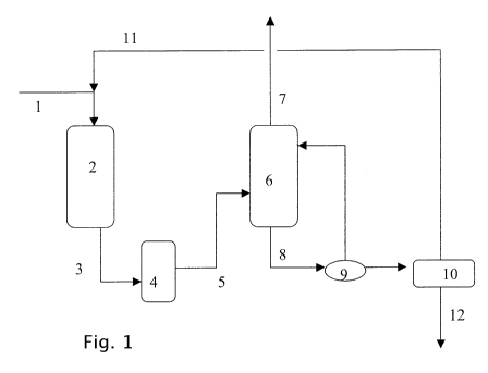
The invention will now be illustrated using the
following non-limiting embodiment with reference to the
schematic Figure.
In the figure, gas comprising H2S, C02, HCN and COS
is led via line 1 to HCN/COS hydrolysis unit 2, where
hydrolysis of HCN and COS takes place. The resulting gas,
depleted in HCN and in COS, is optionally washed in
scrubber 4 to remove any NH3 formed and led via line 5 to
an absorber 6. In absorber 6, the gas depleted in HCN and
in COS is contacted with absorbing liquid, thereby
transferring H2S and CO2 from the gas to the absorbing
liquid to obtain absorbing liquid rich in H2S and CO2 and
purified gas. The purified gas leaves absorber 6 via
line 7. The absorbing liquid rich in H2S and CO2 is led
via line 8 to heater 9, where it is heated. The resulting
heated absorbing liquid is de-pressurised in flash vessel
10, thereby obtaining flash gas rich in CO2 and absorbing
CA 02694896 2010-01-28
WO 2009/016139 PCT/EP2008/059843
- 14 -
liquid rich in H2S. The flash gas rich in CO2 is led via
line 11 to HCN/COS hydrolysis unit 2. The absorbing
liquid rich in H2S is led to a regenerator 12, where it
is contacted at elevated temperature with a stripping
gas, thereby transferring H2S to the stripping gas to
obtain regenerated absorbing liquid and stripping gas
rich in H2S. The resulting stripping gas rich in H2S can
then be led to a sulphur recovery unit (not shown).