Note: Descriptions are shown in the official language in which they were submitted.
CA 02695163 2010-01-29
WO 2009/017832 PCT/US2008/009352
1
Title: METHODS FOR APPLYING MICROCHANNELS TO SEPARATE
GASES USING LIQUID ABSORBENTS, ESPECIALLY IONIC LIQUID
(IL) ABSORBENTS
CROSS REFERENCE TO RELATED APPLICATIONS
[0001] This application claims the benefit of U.S. Provisional Application No.
60/962,784, filed August 1, 2007, U.S. Provisional Application No. 60/962,786,
filed
August 1, 2007, U.S. Patent Application No. 12/ , entitled "METHODS FOR
APPLYING MICROCHANNELS TO SEPARATE METHANE USING LIQUID
ABSORBENTS, ESPECIALLY IONIC LIQUID (IL) ABSORBENTS FROM A
MIXTURE COMPRISING METHANE AND NITROGEN," filed August 1, 2008, and
U.S. Patent Application No. 12/ , entitled "METHODS FOR APPLYING
MICROCHANNELS TO SEPARATE GASES USING LIQUID ABSORBENTS,
ESPECIALLY IONIC LIQUID (IL) ABSORBENTS," filed August 1, 2008, all of which
are incorporated by reference.
BACKGROUND OF THE INVENTION
[0002] The present invention relates to methods of separating gasses and, more
particularly to the methods of separating gasses using microchannel devices
and
ionic liquid absorbents.
[0003] The Losey paper describes a contacting method for a gas and a liquid
reaction system but does not suggest absorption-desorption as a potential unit
operation. Matthew W. Losey et al, "Microfabricated Multiphase Packed-Bed
Reactors: Characterization of Mass Transfer and Reactions," Ind. Eng. Chem.
Res.
2001, 40, 2555-2562. "Solubilities and Thermodynamic Properties of Gases in
the
Ionic Liquid 1-n-Butyl-3-methylimidazolium Hexafluorophosphate", Anthony, J.,
Maginn, E., and Brennecke, J., J. Phys. Chem B 2002, 106, 7315-7320, describes
one example of an ionic liquid that suggests a single stage separation of
methane
and nitrogen are possible. Both of these articles are incorporated by
reference.
[0004] The use of wicks or capillary structures for thin film is described in
U.S.
Patent Nos. 7,051,540 and 6,875,247, which are incorporated by reference.
Surface
features for multiphase processing are discussed in U.S. Patent Application
Publication Nos. 2007/0085227, 2007/0017633, and 2006/0073080, which are
incorporated by reference.
CA 02695163 2010-01-29
WO 2009/017832 PCT/US2008/009352
2
[0005] Gas separations are discussed in U.S. Patent Nos. 6,579,343 and
6,623,659, U.S. Patent Application Publication No. 2006/0251558, and PCT
Published Application No. WO 02/34863, which are incorporated by reference.
[0006] Options for the absorption and desorption of S02 from flue gas
independently or in conjunction with C02 absorption and desorption have been
considered by a few researchers (Wu, W., Han, B., Gao, H., Liu, Z., Jiang, T.,
Huang, J., "Desulfurization of flue gas: S02 absorption by an ionic liquid,"
Angew.
Chem. Int. Ed., vol. 43, pp. 2415-2417, 2004; Anderson, J.L., Dixon, J.K,
Maginn,
E.J., Brennecke, J.F., "Measurement of S02 solubility in ionic liquids," The
Journal of
Physical Chemistry B, vol. 110, no. 31, pp. 15059-15062, 2006, each of which
is
incorporated by reference). Problems with typical wet and dry absorption
techniques, including large water requirements and post-absorption treatment,
dust
formation and sorbent poisoning, plugging, or deactivation have led to
consideration
of ionic liquids as potential sorbents.
[0007] Foam flow is discussed in Stemmet,C.P., Jongmans, J.N., van der Schaaf,
J., Kuster, B.F.M., Schouten, J.C., "Hydrodynamics of gas-liquid counter-
current flow
in solid foam packings," Chemical Engineering Science, 60, 6422-6429, 2005;
Stemmet,C.P., van der Schaaf, J., Kuster, B.F.M., Schouten, J.C., "Solid Foam
Packings for Multiphase Reactors - Modelling of Liquid Holdup and Mass
Transfer,"
Trans. ChemE, Part A, Chemical Engineering Research and Design, 84 (A12), 1134-
1141, 2006; and Stemmet,C.P., Meeuwse, M., van der Schaaf, J., Kuster, B.F.M.,
Schouten, J.C., "Gas-liquid mass transfer and axial dispersion in solid foam
packings," Chemical Engineering Science, 62, 5444-5450, 2007. The
aforementioned references are incorporated herein by reference.
INTRODUCTION TO THE INVENTION
[0008] Embodiments of the present invention include methods of using
microchannel separation systems including absorbents to improve thermal
efficiency
and reduce parasitic power loss. Energy is typically added to desorb a solute
and
then energy or heat is removed to absorb a solute using a working solution.
The
working solution or absorbent may comprise an ionic liquid, or other fluids
that
demonstrate a difference in affinity between a solute and other gasses in a
solution.
CA 02695163 2010-01-29
WO 2009/017832 PCT/US2008/009352
3
[0009] The application of microchannel separation systems using absorbents
represents an opportunity for improved efficiency by integrating a complete
system
and reducing parasitic power loss. Energy is typically added to desorb the
solute
and then removed to absorb the solute using the working solution. The working
solution or absorbent may comprise an ionic liquid, an amine solution for
primarily
carbon dioxide or -H2S separation, or other fluids that demonstrate a
difference in
affinity between two or more solutes.
[0010] An ionic liquid is one absorbent option that can be sued in its pure
form or
in conjunction with water or other solvent. Ionic liquids have a relatively
low (below
100 C) melting point and are typically liquid at room temperature.
[0011] In a first aspect, a method for separating gaseous components according
to the present invention may include contacting a gaseous mixture with an
ionic
liquid by flowing the gaseous mixture and the ionic liquid through a
microchannel;
absorbing at least a portion of a first component of the gaseous mixture by
the ionic
liquid, thereby creating a resultant mixture including a resultant gas and the
ionic
liquid; directing the resultant gas away from the ionic liquid; and desorbing
at least
some of the first component gas from the ionic liquid by changing the
temperature of
the ionic liquid.
[0012] In a detailed embodiment of the first aspect, the step of desorbing at
least
some of the first component gas may include raising the temperature of the
ionic
liquid. In another detailed embodiment of the first aspect, the step of
desorbing at
least some of the first component gas may include lowering the temperature of
the
ionic liquid. In yet another detailed embodiment of the first aspect, the step
of
desorbing at least some of the first component gas includes lowering the
pressure of
the ionic liquid. In still another detailed embodiment of the first aspect,
the method
may include the step of changing the temperature of the ionic liquid prior to
the step
of absorbing at least a portion of the first component gas.
[0013] In another detailed embodiment of the first aspect, the step of
desorbing at
least some of the first component gas may include raising the pressure of the
ionic
liquid. In a further detailed embodiment, the step of changing the temperature
of the
ionic liquid may include lowering the temperature of the ionic liquid. In
another
further detailed embodiment, the step of changing the temperature of the ionic
liquid
CA 02695163 2010-01-29
WO 2009/017832 PCT/US2008/009352
4
may include raising the temperature of the ionic liquid. In still another
further
detailed embodiment, thermal energy extracted from the ionic liquid in one of
the
desorbing and changing the temperature steps may be supplied to the ionic
liquid in
the other of the desorbing and changing the temperature steps.
[0014] In another detailed embodiment of the first aspect, the microchannel
may
include at least one flow mixing feature. In a further detailed embodiment,
the flow
mixing feature may include a porous packed bed including at least one of rings
and
spheres. In another further detailed embodiment, the flow mixing feature may
include a porous foam, felt, wad and/or other porous structure continuous for
at least
a length greater than a length of three hydraulic diameters of the
microchannel,
wherein the porosity is less than one. In another exemplary embodiment, the
chamber that houses the foam structure may range from 2 mm to 50 mm, for
example, and a microchannel dimension may be found elsewhere in the process,
including integrated heat or mass exchangers or mixers. In an alternate
embodiment, the effluent from a large absorption section may feed to two or
more
channels downstream, wherein the channels are in the microchannel dimension
and
wherein the channels are used for heat or mass exchange or mixing.
[0015] In another detailed embodiment of the first aspect, the contacting step
may
include flowing the gaseous mixture and the ionic liquid co-currently through
the
microchannel. In yet another detailed embodiment of the first aspect, the
contacting
step may include flowing the gaseous mixture counter-currently to the ionic
liquid
through the microchannel.
[0016] In still another detailed embodiment of the first aspect, the
microchannel
may include a a foam, wad, and/or mesh. In a further detailed embodiment, the
flowing step may include wetting the foam, wad, and/or mesh with the ionic
liquid. In
another further detailed embodiment, the microchannel may include a foam
constructed from aluminum, carbon, copper, nickel, stainless steel, alumina,
silicon
carbide, and/or other structurally sound foam or other porous material. In yet
another further detailed embodiment, the microchannel may include a foam
coated
with a material to increase the wetting over the underlying material. In still
another
further detailed embodiment, the microchannel may include a plurality of foams
having different pore densities.
CA 02695163 2010-01-29
WO 2009/017832 PCT/US2008/009352
[0017] In another detailed embodiment of the first aspect, the gaseous mixture
may include methane and nitrogen. In a further detailed embodiment, the first
component gas may include methane and the resultant gas may include nitrogen.
[0018] In another detailed embodiment of the first aspect, the gaseous mixture
may include carbon dioxide. In a further detailed embodiment, the first
component
gas may include carbon dioxide.
[0019] In another detailed embodiment of the first aspect, the first component
gas
may include oxygen gas. In yet another detailed embodiment of the first
aspect, the
first component gas may include a nitrogen compound. In still another detailed
embodiment of the first aspect, the method may include the step of using the
resultant gas in a subsequent process. In another detailed embodiment of the
first
aspect, the first component gas may include at least one of nitrogen, hydrogen
sulfide, ammonia, Ni(CO)4, and a thiol.
[0020] In another detailed embodiment of the first aspect, the ionic liquid
may
have been diluted to reduce the viscosity by at least 5% from the neat
material. In a
further detailed embodiment, the ionic liquid may have been diluted with
greater than
0.1 % water.
[0021] In a second aspect, a method for separating component gases from a
gaseous mixture according to the present invention may include the steps of
providing a gaseous mixture including a first component gas and a second
component gas; flowing a first ionic liquid and the gaseous mixture through a
first
microchannel; absorbing at least a portion of the first component gas into the
first
ionic liquid while the first ionic liquid and the gaseous mixture flow through
the first
microchannel, thereby forming a first resultant mixture including a first
resultant gas
and the first ionic liquid; flowing the first resultant mixture into a first
liquid/gas
separator; directing the first resultant gas away from the first ionic liquid
using the
first liquid/gas separator; desorbing at least a portion of the first
component gas from
the first ionic liquid by changing the temperature of the first ionic liquid;
flowing a
second ionic liquid and the first resultant gas into a second microchannel;
absorbing
at least a portion of the second component gas into the second ionic liquid
while the
second ionic liquid and the separated first resultant gas flow through the
second
microchannel, thereby forming a second resultant mixture including a second
CA 02695163 2010-01-29
WO 2009/017832 PCT/US2008/009352
6
resultant gas and the second ionic liquid; flowing the second resultant
mixture into a
second liquid/gas separator; directing the second resultant gas away from the
second ionic liquid using the second liquid/gas separator; and desorbing at
least a
portion of the second component gas from the second ionic liquid by changing
the
temperature of the second ionic liquid. In a similar fashion, more than two
ionic
liquids may be used in sequential processing steps of the cycle. In exemplary
embodiments, two or more ionic liquids may be used in sequential processing
steps.
[0022] The foregoing is a summary and thus contains, by necessity,
simplifications, generalization, and omissions of detail; consequently, those
skilled in
the art will appreciate that the summary is illustrative only and is not
intended to be in
any way limiting. Other aspects, features, and advantages of the devices
and/or
processes and/or other subject matter described herein will become apparent in
the
teachings set forth herein.
[0023] In a third aspect, a microchannel device according to the present
invention
may include a first plurality of microchannels; and a second plurality of
microchannels, each of the second plurality of microchannels being separated
from
at least one of the first plurality of microchannels by one of a plurality of
walls. At
least one of the walls may include a plurality of voids, the voids being
arranged to
permit heat transfer from one of the first plurality of microchannels to one
of the
second plurality of microchannels while reducing heat conduction along a
length of
the wall.
[0024] In a fourth aspect, a processing system according to the present
invention
may include a first microchannel including a first absorbent inlet, a first
absorbent
outlet, a feed stream inlet, and a first resultant gas outlet; a second
microchannel
including a second absorbent inlet, a second absorbent outlet, and a second
resultant gas outlet, the second microchannel being arranged in a counterflow
arrangement relative to the first microchannel; an absorbent circulating
through the
first microchannel and the second microchannel. The absorbent may have a
temperature T1 at the first inlet, a temperature T2 and the first outlet, a
temperature
T3 at the second inlet, and a temperature T4 at the second outlet. At least
one of
the following conditions may be satisfied: T2 is greater than T3 and T1 is
greater
than T4.
CA 02695163 2010-01-29
WO 2009/017832 PCT/US2008/009352
7
[0025] In a detailed embodiment of the fourth aspect, the absorbent may have a
Henry's law constant that increases with temperature and T4 may be greater
than
T2. In another detailed embodiment of the fourth aspect, the feed stream inlet
may
receive a flue gas feed including nitrogen and carbon dioxide, the first
resultant gas
outlet may exhaust a first resultant gas having a higher concentration of
nitrogen
than the flue gas feed, and the second resultant gas outlet may exhaust a
second
resultant gas having a higher concentration of carbon dioxide than the flue
gas feed.
In another detailed embodiment of the fourth aspect, the feed stream inlet may
receive a mixture including at least one hydrocarbon and nitrogen, the first
resultant
gas outlet may exhaust a first resultant gas having a higher concentration of
nitrogen
than the mixture, and the second resultant gas outlet may exhaust a second
resultant gas having a higher concentration of the at least one hydrocarbon
than the
mixture.
[0026] In another detailed embodiment of the fourth aspect, the feed stream
inlet
may receive a mixture including at least one hydrocarbon and at least one
contaminant, the first resultant gas outlet may exhaust a first resultant gas
having a
higher concentration of the hydrocarbon than the mixture, and the second
resultant
gas outlet may exhaust a second resultant gas having a higher concentration of
the
contaminant than the mixture. In a further detailed embodiment, the mixture
may be
a natural gas feed and the contaminant may include at least one of H2S, a
thiol, and
another sulfur-containing compound.
[0027] In another further detailed embodiment, the system may include a first
Fischer-Tropsch reactor, where the feed stream inlet is coupled to an outlet
of the
Fischer-Tropsch reactor. In a still further detailed embodiment, the system
may
include a second Fischer-Tropsch reactor and at least one of the first
resultant gas
outlet and the second resultant gas outlet may be coupled to an inlet of the
second
Fischer-Tropsch reactor.
[0028] In another detailed embodiment of the fourth aspect, a difference
between
T1 and T4 may be less than 10 C. In a further detailed embodiment, the
difference
between T1 and T4 may be less than 5 C. In a still further detailed
embodiment, the
difference between T1 and T4 may be less than 2 C. In a further detailed
embodiment, the difference between T1 and T4 may be less than 1 C.
CA 02695163 2010-01-29
WO 2009/017832 PCT/US2008/009352
8
[0029] In another detailed embodiment of the fourth aspect, a difference
between
T2 and T3 may be less than 10 C. In a further detailed embodiment, the
difference
between T2 and T3 may be less than 5 C. In a still further detailed
embodiment, the
difference between T2 and T3 may be less than 2 C. In a further detailed
embodiment, the difference between T2 and T3 may be less than 1 C.
[0030] In a fifth aspect, a processing system according to the present
invention
may include a first microchannel including a first absorbent inlet, a first
absorbent
outlet, a feed stream inlet, and a first resultant gas outlet; a second
microchannel
including a second absorbent inlet, a second absorbent outlet, and a second
resultant gas outlet, the second microchannel being arranged in a counterflow
arrangement relative to the first microchannel; an absorbent circulating
through the
first microchannel and the second microchannel. The absorbent may have a
temperature T1 at the first inlet, a temperature T2 and the first outlet, a
temperature
T3 at the second inlet, and a temperature T4 at the second outlet. At least
one of
the following conditions may be satisfied: T3 is greater than T2, T4 is
greater than
T1, and T2 is greater than T4.
[0031] In a detailed embodiment of the fifth aspect, the feed stream inlet may
receive a mixture including nitrogen and oxygen, the first resultant gas
outlet may
exhaust a first resultant gas having a higher concentration of nitrogen than
the
mixture, and the second resultant gas outlet may exhaust a second resultant
gas
having a higher concentration of oxygen than the mixture.
[0032] In another detailed embodiment of the fifth aspect, the feed stream
inlet
may receive a mixture including at least one hydrocarbon and at least one
contaminant, the first resultant gas outlet may exhaust a first resultant gas
having a
higher concentration of the hydrocarbon than the mixture, and the second
resultant
gas outlet may exhaust a second resultant gas having a higher concentration of
the
contaminant than the mixture. In a further detailed embodiment, the mixture
may be
a natural gas feed and the contaminant may be at least one of H2S, a thiol,
and
another sulfur-containing compound. In another further detailed embodiment,
the
system may include a first Fischer-Tropsch reactor, where the feed stream
inlet is
coupled to an outlet of the Fischer-Tropsch reactor. In a still further
detailed
embodiment, the system may include a second Fischer-Tropsch reactor and at
least
CA 02695163 2010-01-29
WO 2009/017832 PCT/US2008/009352
9
one of the first resultant gas outlet and the second resultant gas outlet may
be
coupled to an inlet of the second Fischer-Tropsch reactor.
[0033] In another detailed embodiment of the fifth aspect, a difference
between
T1 and T4 may be less than 10 C. In a further detailed embodiment, the
difference
between T1 and T4 may be less than 5 C. In a still further detailed
embodiment, the
difference between T1 and T4 may be less than 2 C. In a further detailed
embodiment, the difference between T1 and T4 may be less than 1 C.
[0034] In another detailed embodiment of the fifth aspect, a difference
between
T2 and T3 may be less than 10 C. In a further detailed embodiment, the
difference
between T2 and T3 may be less than 5 C. In a still further detailed
embodiment, the
difference between T2 and T3 may be less than 2 C. In a further detailed
embodiment, the difference between T2 and T3 may be less than 1 C.
[0035] In a sixth aspect, a processing device according to the present
invention
may include a pump having an suction and a discharge and a plurality of
microchannels, each of the plurality of microchannels having an inlet and an
outlet.
Each of the inlets may be directly fluidically connected to the discharge and
each of
the outlets may be directly fluidically connected to the suction.
[0036] In a detailed embodiment of the sixth aspect, the inlets may be
arranged
radially around the discharge. In a further detailed embodiment, the inlets
may be
symmetrically arranged.
[0037] In another detailed embodiment of the sixth aspect, the outlets may be
arranged radially around the suction. In a further detailed embodiment, the
outlets
may be symmetrically arranged.
[0038] In a seventh aspect, a method of processing a material according to the
present invention may include forming a plurality of miscelles in an ionic
liquid in a
microreactor; crystallizing the miscelles to form crystals; and separating the
crystals
from the ionic liquid.
[0039] In a detailed embodiment of the seventh aspect, the step of forming a
plurality of miscelles in an ionic liquid may include controlling at least one
of
temperature, residence time, and addition of reactants.
CA 02695163 2010-01-29
WO 2009/017832 PCT/US2008/009352
[0040] In an eighth aspect, a method of processing a material may include
flowing
two fluids into a microchannel, the two fluids including a continuous phase
and a
discontinuous phase, at least one of the continuous phase and discontinuous
phase
including an ionic liquid; and combining the continuous phase and the
discontinuous
phase in the microchannel to form at least one of an emulsion and a
dispersion.
[0041] In a detailed embodiment of the eighth aspect, the step of combining
the
continuous phase and the discontinuous phase may include controlling at least
one
of temperature, residence time, and addition of reactants.
[0042] In a ninth aspect, an emulsion may include a continuous phase and a
discontinuous phase, where at least one of the continuous phase and the
discontinuous phase is an ionic liquid.
[0043] In a detailed embodiment of the ninth aspect, the continuous phase may
be an ionic liquid. In a further detailed embodiment, the discontinuous phase
may
include a plurality of micelles.
[0044] The foregoing is a summary and thus contains, by necessity,
simplifications, generalization, and omissions of detail; consequently, those
skilled in
the art will appreciate that the summary is illustrative only and is not
intended to be in
any way limiting. Other aspects, features, and advantages of the devices
and/or
processes and/or other subject matter described herein will become apparent in
the
teachings set forth herein.
BRIEF DESCRIPTION OF THE SEVERAL VIEWS OF THE DRAWING
[0045] The detailed description particularly refers to the accompanying
Figures in
which:
[0046] FIG. 1 is a diagram showing an exemplary process for extracting C02
from a flue gas feed;
[0047] FIG. 2 is a schematic diagram of an exemplary thermal compressor
utilizing an ionic liquid;
[0048] FIG. 3 is a schematic diagram of an exemplary thermal compressor
utilizing an ionic liquid and an absorption refrigeration cycle;
CA 02695163 2010-01-29
WO 2009/017832 PCT/US2008/009352
11
[0049] FIG. 4 is a diagram of an exemplary absorption/desorption process of
carbon dioxide into an ionic liquid for separation;
[0050] FIG. 5 is a cross-sectional view of an exemplary microchannel heat
exchanger core;
[0051] FIG. 6 is a plot of temperature versus heat exchanger length showing a
calculated temperature profile of an exemplary microchannel heat exchanger;
[0052] FIG. 7 is a cross-sectional view of an exemplary jet-enhanced
contactor;
[0053] FIG. 8 is a diagram of an exemplary multi-stage integrated system for
the
capture of hydrocarbons;
[0054] FIG. 9 is a cross-sectional view of an exemplary gas liquid contactor
using
an apertured substrate;
[0055] FIG. 10 is a cross-sectional view of an exemplary gas liquid contacting
unit;
[0056] FIG. 11 is an isometric view of an exemplary macromanifold arrangement
in a typical microchannel reactor box;
[0057] FIG. 12 is a diagram of an exemplary macromanifold arrangement;
[0058] FIG. 13 is a diagram of an exemplary macromanifold arrangement having
a reduced macromanifold volume;
[0059] FIG. 14 depicts and exemplary absorption and desorption system
[0060] FIG. 15 is a diagram of an exemplary system for removing C02 from a
flue
gas feed;
[0061] FIG. 16 is a diagram of an exemplary integrated absorption desorption
system in a single block to recuperate heat from the two half cycles to reduce
the
overall parasitic power loss;
[0062] FIG. 17 is a diagram of an exemplary system for efficiently
transferring
energy between absorption and desorption cycles to reduce parasitic power use;
[0063] FIG. 18 is a diagram of an exemplary separation system for the
purification
of oxygen from air;
[0064] FIG. 19 is an isometric view of an exemplary solid foam processing
device;
CA 02695163 2010-01-29
WO 2009/017832 PCT/US2008/009352
12
[0065] FIG. 20 is an isometric view of an alternative exemplary solid foam
processing device;
[0066] FIG. 21 is a cross-sectional view of an exemplary feed port assembly;
[0067] FIG. 22 is an exploded isometric view of an exemplary feed port
assembly;
[0068] FIG. 23 is an exploded isometric view of an exemplary feed port
assembly;
[0069] FIG. 24 is a cross-sectional view of an alternative exemplary feed port
assembly.
[0070] FIG. 25 is an exploded isometric view of an alternative exemplary feed
port assembly;
[0071] FIG. 26 is a detailed exploded isometric view of an alternative
exemplary
feed port assembly;
[0072] FIG. 27 is a diagram of an exemplary multiphase manifold where the
liquid
inlet is substantially in contact with the foam or the continuous connected
porous
media;
[0073] FIG. 28 is a diagram showing an exemplary process for the purification
of
methane from a mixture comprising methane and nitrogen;
[0074] FIG. 29 is a diagram showing an exemplary integrated
absorption/desorption system in a single block to recuperate heat from the two
half
cycles to reduce the overall parasitic power loss;
[0075] FIG. 30 is an alternate exemplary system for efficiently transferring
energy
between absorption and desorption cycle to reduce parasitic power use;
[0076] FIG. 31 is a diagram showing an exemplary heat recuperation concept in
a
absorption/desorption process of methane into ionic liquid for separation;
[0077] FIG. 32 is piping and instrumentation diagram of an exemplary
microchannel test stand;
[0078] FIG. 33 is an isometric view of an exemplary microchannel device;
[0079] FIG. 34 is diagram showing exemplary embedded mixing features in a
microchannel device;
CA 02695163 2010-01-29
WO 2009/017832 PCT/US2008/009352
13
[0080] FIG. 35 is that graphical result of a computational fluid dynamics
simulation of the flow patterns (as shown by fluid path lines that trace the
movement)
during the mixing of a gas and liquid in the microchannel device of FIG. 34;
[0081] FIG. 36 is detailed view of detail A of the result of the computational
dynamics simulation of FIG. 35;
[0082] FIG. 37 is detailed view of detail B of the result of the computational
dynamics simulation of FIG. 35;
[0083] FIG. 38 is a piping and instrumentation of an exemplary microchannel
test
stand;
[0084] FIG. 39 is an isometric view of an exemplary microchannel device;
[0085] FIG. 40 is a detailed view of an exemplary port plug of the exemplary
microchannel device of FIG. 39;
[0086] FIG. 41 is a detailed overhead view of the exemplary microchannel
device
of FIG. 39 with the port plugs removed;
[0087] FIG. 42 is a diagram of an exemplary knock-out pot used in the
exemplary
microchannel device of FIG. 39; and
[0088] FIG. 43 is a plot of pressure drop versus liquid flow rate for 100 sccm
vapor and varying liquid flow rates.
DETAILED DESCRIPTION OF THE INVENTION
[0089] In the following detailed description, reference is made to the
accompanying drawings, which form a part hereof. In the drawings, similar
symbols
typically identify similar components, unless context dictates otherwise. The
illustrative embodiments described in the detailed description, drawings, and
claims
are not meant to be limiting. Other embodiments may be utilized, and other
changes
may be made, without departing from the spirit or scope of the subject matter
presented here.
[0090] Exemplary embodiments include a thermally efficient system that
includes
at least an absorption, desorption, and recuperative heat exchange unit
operation.
At least two of these may integrated into a single microchannel apparatus. In
some
embodiments, all three are integrated into a single microchannel apparatus.
CA 02695163 2010-01-29
WO 2009/017832 PCT/US2008/009352
14
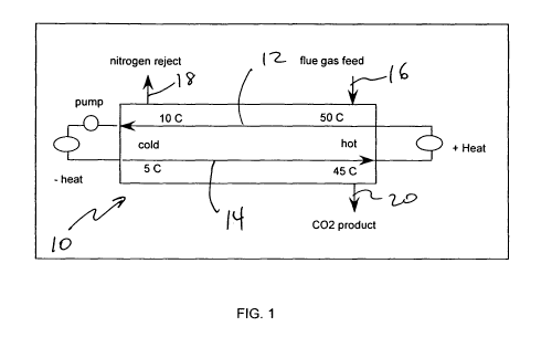
[0091] As shown in FIG. 1, in exemplary three unit operations of absorption,
desorption, and recuperation integrated in a single microchannel apparatus 10,
four
critical temperatures are defined where T1 is the inlet temperature of the
absorbent
at the start of the absorption channel 12, T2 is the outlet temperature of the
absorbent at the end of the absorption section of the channel 12, T3 is the
inlet
temperature at the start of the desorption channel 14 and T4 is the outlet
temperature of the desorption channel 14, wherein T2 is greater than T3 and/or
T1 is
greater than T4. For an exemplary system, heat flows from the absorption unit
operation to the desorption unit operation.
[0092] The applied temperature gradients while counterintuitive aid in the
recuperation of energy between absorption and desorption. Close approach
temperatures are desired between either the T1 and T4 streams at one end of
the
apparatus, the T2 and T3 streams at one end of the apparatus, or both the T1
and
T4 streams and the T2 and T3 streams. The approach temperature between the T1
and T4 end of the apparatus may be less than 10 C, or less than 5C, or less
than
2C, or less than 1 C, or in exemplary embodiments between 0.05 and 1 C. The
approach temperature between the T2 and T3 end of the apparatus may be less
than 10 C, or less than 5C, or less than 2C, or less than 1 C, or in exemplary
embodiments between 0.05 and 1 C. A small amount of energy must be augmented
or added to the absorption fluid as it flows from the desorption 14 to the
absorption
12 channel. A small amount of energy must be removed from the absorbent as it
flows from the absorption to the desorption channel. Further T4 must be
greater
than T2 for absorbents whose Henry's law constants increase with temperature.
[0093] In an alternate embodiment where the Henry's law constant decreases
with temperature, as that reported for oxygen in BmimPF6 ionic liquid, then
the
reverse temperature profile is desirable where T2 is greater than T4 and T3 is
greater than T2 and or T4 is greater than T1.
[0094] In other embodiments, the parasitic power loss for the absorption
system
is less than 20% of the system produced power, and less than 10% in some
embodiments.
[0095] In an alternate embodiment, the process is used to capture dilute
amounts
of a solute 20, roughly less than 30% of the inlet feed stream 16. In this
case, the
CA 02695163 2010-01-29
WO 2009/017832 PCT/US2008/009352
thermal integration scheme may vary and may not need to be as highly
integrated.
In one embodiment, the absorption occurs in a near isothermal zone, as defined
by a
gradient less than 50 C, or less than 20 , or less than 10 C. The unsorbed
species
18 travel through the microchannel absorption unit operation to a second unit
operation for downstream processing, while the dilute species is captured for
either
use elsewhere within a process system, or disposal as a waste product. As an
example, this technology could be used to capture H2S, NH3, Ni-CO, or any
other
dilute species to clean a fluid stream for subsequent downstream processing in
a
reactor, separator, mixer, heat exchanger, or other chemical unit operation.
The
advantage for the capture of the dilute species in a microchannel apparatus is
the
reduced footprint and cost which creates attractive flowsheets for both small
capacity
process systems or large scale systems. As an example, this separation scheme
could be useful for a small scale gas-to-liquids facility to clean up or
remove dilute
unwanted species from the synthesis gas generated from a gassifier,
autothermal
reformer, partial oxidation reactor, steam reformer or any other reactor.
Further, the
clean up technology could be applied to remove H2S, thiols, other sulfur
bearing
species, or other contaminants from natural gas as found in pipelines, natural
gas
wells, or other sources of hydrocarbon feedstocks. The exemplary process has
applications as a gas clean up step for other technologies, including removing
contaminants from any hydrocarbon-laden stream, air, high purity gases for
electronics, welding, or any other application, where the purity must exceed
90% of a
desired component, and more than 95% purity. Applications may also include
methanol synthesis, synthesis of organic liquids or gases, or the purification
of
inorganic fluids.
[0096] Exemplary embodiments may include thin film separations. For example,
mesh flow with counterflow of feeds such that the flow of the liquid absorbent
is
retained or constrained within a channel or structure by the use of capillary
forces
that minimize the mixing or back mixing of a liquid and a gas in a
microchannel.
[0097] Exemplary embodiments may include mixed phase flow using surface
features, for example a one pass process with co-flow feeds. The fluid mixture
of
liquid and gas are co-fed either inside or outside of the microchannel device
and flow
in a co-flow arrangement. The fluid is pushed and pulled in and out of the
surface
features.
CA 02695163 2010-01-29
WO 2009/017832 PCT/US2008/009352
16
[0098] Exemplary embodiments may include multiphase flow through packed bed
with co-flow of feeds. The gas and liquid flow in a co-flow arrangement and
are
mixed to create a high interfacial area by flowing past a series of
obstructions in the
form of posts, baffles, and/or a porous packed bed of rings, spheres, or other
shapes.
[0099] Exemplary embodiments may include contactor based absorption and
desorption unit operations where a thin contactor plate separates the phases
to
assist with countercurrent flow. The contactor plate has sufficiently small
apertures
such that capillary pressure of the liquid retains the liquid on one side of
the
contactor plate and the gaseous stream on the other side of the contactor
plate.
[00100] Exemplary embodiments may include foam flow, where the gas and liquid
stream flow substantially through a foam, wad, mesh or other porous and
connected
media. The connected media may be assembled with the close coupling of several
porous media, such as a stack of foams rather than assembled from a
discontinuous
array of particles such as pellets or beads. The flow of gas and liquid
sorbent
through the foam may be countercurrent or co-current. The liquid
preferentially wets
the foam or continuous and connected media to increase the surface area and
absorbs one or more species during the absorption cycle and desorbs one or
more
species during the desorption cycle.
[00101] Exemplary systems including multiple unit operations may be configured
to
reduce the amount of additional energy or power required to drive the
separation
process. For example, an exemplary microchannel absorber uses an ionic liquid
to
absorb a solute gas from a feed gas comprising same. The feed gas flows into
the
absorber at a first temperature and pressure. The solute is preferentially
absorbed
into the ionic liquid or other absorbent, while the less strongly absorbed
solute, which
has much less affinity to absorption by the ionic liquid or other absorbent,
passes
through and exits the absorber as a lean gaseous stream.
[00102] The solute may be desorbed in a second unit operation. Increasing the
temperature reduces the affinity for the absorbed solute and therefore desorbs
the
solute. For example, the Henry's constant for oxygen is 23000 bar at 10 C and
drops to 1550 bar at 50 C. The temperature of an absorbed mixture of oxygen
and
BmimPF6 would be decreased to desorb the oxygen. Alternative ionic liquids or
CA 02695163 2010-01-29
WO 2009/017832 PCT/US2008/009352
17
other absorbents may have a different response of a cold absorption and hot
desorption. In another exemplary embodiment, the temperature may be either
increased or decreased to assist with the desorption of the solute and/or the
pressure may be decreased to also assist with the desorption of the solute.
[00103] Other exemplary embodiments include single unit operation with a cold
and a hot end to recuperate energy between absorption and desorption to
improve
the energy recovery and system efficiency. Also, two unit operations (one cold
and
one hot), where energy is recuperated between the unit operations to reduce
the
parasitic power requirement. In another exemplary embodiment, a distillation
type
configuration includes an interior feed point and a concentrated methane
stream
removed at the top of the channel and a concentrated nitrogen stream removed
at
the bottom of the column. Heat may be required to add or remove at the top and
or
bottom or interior points of the channel.
[00104] A solute may have little or no affinity in the liquid absorbent and
may be
removed at the end of the absorption channel, while the sorbed species are
absorbed into the liquid. The liquid may be pumped to a desorption stage,
where the
sorbed gases or liquids are removed. A single stage absorption may be
required.
[00105] If the undesired absorbate is partially absorbed in a selected ionic
liquid,
then multiple stages may be required and a counter flow of the liquid and gas
may
be advantageous.
[00106] Exemplary embodiments may perform CO2 removal from a stream to
either purify a product stream or to capture carbon dioxide for reuse or
sequestration
with a small amount of parasitic power loss. It has been suggested that a
conventional amine separation system requires on the order of 40% of the power
plant energy to capture carbon dioxide from a power plant flue gas. An
exemplary
system requires less than 20% parasitic power loss. In alternate embodiments,
less
than 10% and in some cases less than 5% parasitic power loss could be enabled
with the described microchannel absorption system.
[00107] Other exemplary embodiments may perform 02 removal from a stream.
For some systems, the removal of oxygen represents a system advantage to
either
remove a reaction species for purification of a product or to capture oxygen
for use in
other applications. Exemplary systems may incorporate a high degree of thermal
CA 02695163 2010-01-29
WO 2009/017832 PCT/US2008/009352
18
integration as to reduce the parasitic power loss or reduce the specific power
(kW-
hr/ton 02) required to purify the oxygen.
[00108] In another exemplary embodiment, sulfur may be removed from a plant
feed. Sulfur often represents an unwanted species that may foul a catalyst or
contaminate a product stream or the exhaust stream vented to the environment.
Capture of the sulfur species with a minimal requirement of additional energy
may
represent a system advantage.
[00109] In other exemplary embodiments, other gases, dilute or concentrated,
may
be removed from a solute-containing stream, where the purified stream is used
for a
downstream unit operation. For example, the purified stream may be used for a
reaction, mixing, second separation process, heat exchange, and the like.
Other
exemplary embodiments may remove other gases, dilute or concentrated, from a
solute-containing stream, where the purified stream is a final product that is
packaged for market delivery.
[00110] Exemplary microchannel separation systems may provide unique
advantages for biofuels to concentrate the reactants from a gasifier before
entering a
production reactor that may include a Fischer Tropsch or DME or methanol
synthesis
reactor, to remove or reduce the myriad of contaminants that may comprise a
feed
source, especially from municipal or other waste sources, and finally to
concentrate
the oxygen to enable a more efficient gasifier that does not operate directly
on air but
rather a more efficient source of pure or concentrated oxygen. For example,
air
separation for the gasifier feed may include high conversion of 02 (99+%) and
enriched air (90+%) to reduce the amount of diluent (nitrogen) in the gasifier
and
thus the gasifier size and cost.
[00111] Exemplary embodiments may be used for gas cleanup, in which the
absorption process may be used to remove H2S, NH3, C02, N2, heavy tars, and
other impurities, for example.
[00112] Exemplary embodiments may also be utilized to remove C02 from the
gaseous product of a Fischer Tropsch (FT) reactor. For a highly carbon and
thermal
efficient Fischer Tropsch system, the effluent from the outlet of a first
stage FT
reactor is supplied to a second stage FT reactor. Removal of the carbon
dioxide and
or methane from the first FT product stream concentrates the reactant stream
for the
CA 02695163 2010-01-29
WO 2009/017832 PCT/US2008/009352
19
inlet of the second FT reactor. A more concentrated reactant stream reduces
the
size and cost of the second stage of the FT reactor system.
[00113] For oxygen applications, high purity is desired for a number of
applications, including merchant applications, chemical processing, medical,
and
welding among others. For these applications greater than 99% oxygen is sought
and it is desired to have an efficient source of the oxygen and thus reduce
the
energy requirement to concentrate oxygen.
[00114] Enriched air, including enriched air at >90% purity, also represents
applications for some chemical processing including oxidation reactions,
medical,
and combustion processes. Enriched air can improve the performance of furnaces
used in many industries, including chemical, petroleum, and metal processing
(e.g.
steel processing). Applications include the combustion of a fuel comprising
hydrogen, methane, and/or carbon monoxide to drive the endothermic methane
steam reforming reaction. Enhanced air at 50% or greater oxygen also
represents
an opportunity for a thermally advantaged system especially for the fuel
combustion
that drives the endothermic methane steam reforming reaction. For these
applications, the application system will not be advantaged if the energy
requirement
to purify the oxygen is high. For the described thermally advantaged oxygen
capture
systems, the specific power requirement to produce oxygen may be less than
1000
kW-hr/ton, less than 500 kW-hr/ton, or less than 250 kW-hr/ton. In one
embodiment
it may be less than 200 kW-hr/ton and in another between 50 and 250 kW-hr/ton.
[00115] Other exemplary applications for the Gas to Liquids processes includes
the removal of nitrogen from the FT tail gas to reduce the diluent and in turn
reduce
the size and cost of the reactors. In addition the an exemplary system may be
used
to capture water from the combustion exhaust stream to reduce the requirement
for
fresh water in a gas to liquids or other application. Reduction of fresh water
is of
particular advantage for off-shore or remote processing environments. It may
also
be advantageous in a non-attainment area to reduce the need for fresh water or
the
rejection of process water into a local ecosystem.
[00116] For natural gas processing plants, the removal of acid gases including
C02 and H2S in a thermally efficient manner may represent an advantage for the
CA 02695163 2010-01-29
WO 2009/017832 PCT/US2008/009352
upgrading of natural gas including sour sources in an economic and efficient
process.
[00117] Another application for an exemplary system is the purification of
oxygen
from air or production of air enriched with oxygen to drive an autothermal
reformer to
be used for hydrogen or syngas production, which may be used in a fuel
processing,
fuel cell, or a gas to liquids system. In an alternate embodiment, the
purified air may
be used in a partial oxidation system for converting a hydrocarbon, including
methane, to synthesis gas.or any hydrocarbon to a useful oxygenated
hydrocarbon
or an olefinic product.
[00118] Landfill gas is may also benefit from the removal of nitrogen and or
acid
gas and or other trace contaminants that will deleteriously impact the
downstream
processing catalysts required to upgrade the gas to either the purity of a
natural gas
pipeline or for the conversion to a liquid fuel.
[00119] Additional exemplary applications of enriched air include enhancement
of
bioreactors, including fermentation.
[00120] Gas Separations
[00121] The prior art discusses the use of ionic liquids for acid gas removal
from
light gases; separation of olefins from paraffins, dienes from olefins, and
aromatics
from olefins; removal of mercaptans from hydrocarbon streams. The prior art
also
teaches use of ionic liquids as an additive to improve distillation of close
boiling
compounds. However, the prior art does not teach selective
absorption/desorption
of compounds within a homologous series of hydrocarbons, e.g. C2 from C3, etc.
[00122] Differences in relative absorption capacities with respect to
temperature or
pressure may be used to enhance separation of natural gas liquids (NGL). The
current practice for separating natural gas liquids in a gas processing plant
involves
distillation for purification of each of the desired products, e.g. ethane,
propane,
butane, pentane. Distillation operations have a large footprint, and consume
energy
which otherwise could have been recovered as a hydrocarbon product. A train of
microchannel-based multiple absorption/desorption zones within one device or
multiple devices may be used to provide multiple equilibrium stages for
separation of
NGL products based on relative absorption capacities. Microchannel-based heat
CA 02695163 2010-01-29
WO 2009/017832 PCT/US2008/009352
21
exchangers can provide integrated recuperative heat exchange to recover energy
used for desorption.
[00123] Pump Implant
[00124] A limitation with minimizing energy consumption for microchannel-based
processes requiring pumping relates to the practical limitations of pumping
efficiency
of multiple streams at low flow rates vs. the pump efficiency of one stream at
a high
flow rate. Input of mechanical work, including pumping, is typically most
efficient at
higher flow rates to preserve an acceptable efficiency for work input. The
result is
that input of mechanical energy to a working fluid is usually supplied to a
stream
outside of a microchannel device; this approach requires manifolding between
the
macro and micro scales, resulting in excess dead volume for the fluid and, as
well as
loss in exergetic efficiency.
[00125] One way to counter this limitation is to design the microchannel
apparatus
to be built around the casing of a pump, wherein individual connecting
channels or
submanifolds are directed symmetrically into the suction side of a pump
casing, and
then discharged symmetrically on the discharge side of the pump casing.
Alternatively, the pump casing may be built into the microchannel device to
accomplish the same aforementioned goal.
[00126] An exemplary embodiment includes directing microchannels or
submanifold channels in a radial or spherical direction in the suction (inlet)
and/or
discharge (outlet) entrances of the pump. The microchannels connecting to the
pump cavity may need to be at a different angle or orientation than the
microchannels used to conduct additional unit operations, such as mixing, heat
exchange, chemical reaction, and chemical separation. The pump may be of the
centrifugal type, using acceleration of fluid around a moving shaft. The pump
may
include a seal through which the moving shaft is connected to an exterior
motor.
[00127] Emulsification and Crystallization using Ionic Liquids in
Microchannels
[00128] Many compositions and properties are possible for ionic liquid
solvents,
which can be tailored using suitable design and chemical synthesis techniques.
Micelles of materials can be formed within an ionic liquid solvent, and the
size and
morphology of the micelles can change with process conditions (e.g.
temperature).
CA 02695163 2010-01-29
WO 2009/017832 PCT/US2008/009352
22
[00129] Microreactors can be used to precisely control temperature, residence
time, and addition of components/reactants in order to form tailored micelles
in an
ionic liquid medium. Formation of the micelles may be used as a step in a
crystallization process, wherein the solids are formed with controlled size
and
morphology. Once formed, the solids may be removed with a subsequent
separation step. The ionic liquid is used in this case as a green solvent
which
assists the formation of the micelle.
[00130] Ionic Liquid in Thermal Compressor
[00131] The properties of ionic liquid can be tailored to provide thermal and
transport properties as desired. This ability enables ionic liquids as a good
candidate
for absorbents in thermal compressors and in applications requiring thermal
compressor such as vapor absorption refrigerators.
[00132] A schematic of an exemplary thermal compressor 30 is shown in FIG. 2.
A
thermal compressor is an example of utilizing waste heat (available at T>100
C)
from another process to convert a low temperature/pressure fluid to high
temperature/pressure fluid. The absorbate at low temperature and pressure is
absorbed in the absorbent in the absorber 32. This process will require heat
removal
(Qa) as the mixing process gives out heat of mixing. For some ionic liquids,
the heat
of absorption has been reported as endothermic and thus the temperature of the
working solution or absorbent will decrease during absorption. The absorbate
rich
solution is then pumped to Desorber 34 which operates at higher pressure and
temperature by utilizing waste heat (Qd) from other processes. In desorber 34,
the
high temperature removes the absorbate from the mixture and the absorbate is
now
available at high pressure and temperature. The work input at pump 36 is small
(Wp)
while the absorbent rich solution is sent back to the absorber 32 through
solution
heat exchanger 38 and valve 40 (or a pressure reducing medium). The solution
heat
exchanger 38 exchanges heat between absorbate rich solution and absorbent rich
solution to reduce heat duties of absorber 32 and desorber 34. The work input
from
the pump 36 (Wp) is generally small while heat input (Qd) is available as
waste heat
source, so the thermal compressor 30 can operate at a low operating cost. The
exemplary system is thermally integrated using microchannel heat exchangers 38
CA 02695163 2010-01-29
WO 2009/017832 PCT/US2008/009352
23
and/or absorption and desorption channels to reduce the system parasitic power
loss.
[00133] The high temperature and pressure absorbate can be used for absorption
refrigeration cycle as shown in FIG. 3. In vapor absorption cycle, the
absorbate is
sent to condenser 52 where it condensers fully or partially and then send to
evaporator 54 via a pressure reducing valve 56. The absorbate is either
partially or
fully condensed when it goes through the pressure reducing valve 56. The
absorbate
is heated up in evaporator 54 using the heat from the source that requires
cooling.
The generated vapor goes to the absorber thus completing the cycle.
[00134] The ability to manipulate ionic liquids properties provides several
advantages for use in thermal compressor and its applications. Generally the
ionic
liquids have strong affinity for gases such as hydrocarbons allowing less
absorbent
required for the system. The ionic liquids are generally stable over a range
of
temperature which is also an important requirement for the absorbent in a
thermal
compressor. The high volatility ratio results in easier separation of
absorbate and
absorbent in the desorber 34 improving the overall efficiency of the cycle. In
some
embodiments, ionic liquids can also be used in a double effect absorption
cycle.
[00135] In one exemplary embodiment components of thermal compressor and
vapor absorption cycle (evaporator 54, absorber 32, desorber 34, condenser 52)
are
conventional devices. In another exemplary embodiment, components of thermal
compressor and vapor absorption cycle (evaporator, absorber, desorber,
condenser)
are microchannel devices.
[00136] Microchannel Heat Exchanger to Recuperate Ionic Liquid Sorbent
[00137] It may be advantageous to reduce the parasitic energy loss in the
absorption/desorption process of, for example, methane into ionic liquid for
separation in order to make the system operation economical. This means to
reduce
the energy input "-heat" or "+heat" in the exemplary system 60 shown in FIG.
4,
which is equivalent to having a heat recuperation with very tight temperature
approach at the hot and cold end.
[00138] An exemplary microchannel heat exchanger/recuperator is disclosed here
in a design example of the following performance conditions:
CA 02695163 2010-01-29
WO 2009/017832 PCT/US2008/009352
24
Liquid flow rate: 54,000 Umin; closed loop system
CP = 1407 J/mol-K
density = 1.37 gm/cc
viscosity = 30 cP
Tmax = 50 C
T,oW=10C
Thermal conductivity= 0.19 W/m-K
Approach temperature target 0.1 to 0.25 K on each end.
Liquid volume 1000-10000 liter.
Material: stainless steel.
[00139] In an exemplary embodiment shown in FIG. 5, a counter-current flow
arrangement is used in the device 62. The microchannel wall 64 is 0.01" thick
that
separates the hot and cold liquids, while the channel gap size 66 is also
0.01". For
the above given flow rate at each side, a total length of 48" is necessary to
achieve a
0.25 K approach temperature at the two ends for a goal of a temperature
differential
near 40 C between the hot and cold ends of the absorption and desorption
system.
For a system requiring a smaller temperature difference to achieve a desired
system
capacity for the absorbed solute, perhaps 20 C or 10 C or more or less
difference
between maximum and minimum temperature, then the advantaged process may
have a shorter heat exchanger length less than 48" to achieve a very small (<1
C)
approach temperature.
[00140] FIG. 6 shows a calculated temperature profile of the exemplary
microchannel heat exchanger.
[00141] Table 1 provides exemplary parameters of the ionic liquid heat
exchanger
with 0.25 K approach temperature.
CA 02695163 2010-01-29
WO 2009/017832 PCT/US2008/009352
Table 1
# of channel 5000000
Density 1370 kg/m3
Total Flow Rate 50000 Umin
4110000 kg/h
Flow rate /channel 0.01 Umin
822 g/h
Dh 0.038095238 in
0.000967619
A 1.29032E-06 m3
Re 5.707619881
Channel volume 7.86579E-07 m3
Total liquid volume 3.933 m3
Metal volume/channel 9.439E-07 m3
(No perimeter)
4.72 m3
Heat transferred/channel 12.57665 Watts
Total 62883250 Watts
[00142] The building material of the exemplary heat exchanger can be any
chemically compatible metal or non-metal. As long as its thermal conductivity
is in
the range 0.1 - 1000 W/m K, the change in the approach temperature is less
than 1
degree Celsius. However, the liquid conductivity has a great effect. For a
diluted
ionic liquid, for example [bmim][PF6], at a conductivity 0.38 W/m K, the heat
exchanger length can be shortened to less than 30" for the same approach
temperature. Thus, for an optimization combining thermal and chemical
processes, a
diluted ionic liquid with higher thermal conductivity components is an option.
[00143] The Liquid Jet Enhanced Gas-Liquid Contact For Gas Absorption
[00144] For an efficient gas component separation via absorption in liquid
sorbent,
such as separation of CH4 from field gas using ionic liquid, good contact or
mixing
between the gas mixture (feed) and the liquid phase may be desired. However,
because some liquid sorbents are highly viscous, such as the ionic liquid
[bmim][PF6] with a dynamic viscosity of 382 cP at room temperature, to break
up
liquid phase to have a larger-gas-liquid interfacial area is not
straightforward in the
absorption process. Thus, the mass transfer between gas and liquid is often
limited
by lack of good gas-liquid contact or mixing.
CA 02695163 2010-01-29
WO 2009/017832 PCT/US2008/009352
26
[00145] Surface tension that acts at the liquid surface tends to regularize
the
surface based on the facts that a gas-liquid interface possesses a specific
energy
and that liquid is deformable. A drop or a pocket of liquid takes the shape
minimizing
its surface area. On the other hand, there are some situations where a
localized
stress can deform a liquid surface in an extraordinary manner, which may be
used in
exemplary embodiments to enhance gas-liquid contact.
[00146] For example, and as shown in FIG. 7, when a highly viscous liquid 70
(10
- 1000000 cP) is jetted into the same or other also viscous liquid 71 at the
gas-liquid
interface at a high speed (1 mm/s to 100 m/s, for example), the gas is
entrained
between the two liquid parts (the jet and the bath) to form very thin gas film
72 in
between. The thickness of the gas film 72 can be several microns. Some jetted
liquid sheds away from the jet stream to form so-called "anti-bubble" 74which
is a
liquid droplet completely separated from the bulk liquid by thin gas film 72.
However,
these "anti-bubbles" are not stable generally. After their breakups, very
small gas
bubbles 76 are formed downstream of the process channel or the jet zone. In
such
away, the gas and the liquid get excellent contact via a temporally
drastically
increased interfacial area. Hence, mass transfer of the absorbate components
and,
in turn, the absorption process is enhanced. The existence of a gas-liquid
surface at
the jetting site may be important to entrain the gas; thus, the control of the
liquid level
in the mixer or the feed point may be needed. This can be realized by using a
sensor 78, such as electric capacitance or impendence, laser or gamma ray
detector, and a signal feedback controller of the pumps' flow rates of outflow
liquid
and gas residual. In the control logic, the jet flow rate and gas inlet flow
rate may
also be inputs to determine the liquid level inside the process
channel/chamber
space. To the downstream processes, the liquid and gas phases may need to be
separated in a compact configuration, especially when the mixer or the process
channel is in microchannel fashion. An in-line membrane gas-liquid separator
80 is
also disclosed here. The membrane may be of a hydrophobic nature and may be
implemented as part of the downstream channel wall.
[00147] Decomposition of methane hydrates
[00148] Scientists believe that there could be more valuable carbon fuel
stored in
the vast methane hydrate deposits scattered under the world's seabed,
permafrost
CA 02695163 2010-01-29
WO 2009/017832 PCT/US2008/009352
27
and arctic ocean than in all of the known reserves of coal, oil and gas put
together.
Production of methane from hydrates has been made by depressurizing /
gasification
of the natural gas hydrate (NGH) layer plus the existing well-based
technologies.
[00149] On the other hand, besides the current LNG-based energy supply system,
NGH production and utilization systems are also believed to be a new high-
efficient
means to distribute and utilize energy, especially for small to mid-size
markets and
small-scale gas suppliers. The known aspects involved in the NGH technology
development include: multi-component mixed gas hydrate processing
technologies,
technologies to remove the heat from NGH formation by utilizing untapped cold
energy, technologies to enable continuous cooling and depressurizing NGH,
technologies and systems to deliver and use NGH.
[00150] From the above two scenarios, a discharge, gasification or
depressurize
step is required in the NGH production and utilization. Here, depressurization
/
gasification is also referred to decomposition.
[00151] An exemplary controlled NGH decomposition process combined with
adsorption function/process (via liquid or solid sorbent) using microchannel
technology is disclosed. The exemplary process is multi-staged. The system 100
includes microchannel adsorption separators 102, 104, 106, 108, 110 named
"microchannel adsorbers" in FIG. 8. In each microchannel adsorber 102, 104,
106,
108, different sorbents, including ionic liquids, may be used to achieve
maximum
removal of the targeted component by making use of the corresponding pressure
excursion segment in the overall NGH decomposition process. Valves and other
components known to those of skill in the art are not included in FIG. 8 for
clarity.
[00152] Exploiting surface tension effects for separations in microchannel
systems
[00153] Inlet effect and a micro-bubble mixer
[00154] One of the directly useful surface tension effects in microchannel
separation systems is the history effect of two-phase flow pattern, i.e. the
flow or
mixing pattern in the inlet of the microchannel process remains for a distance
downstream. The reason is that the fluids flow downstream in the time needed
to
correct the gas-liquid interface shape. This effect fades in the flow
direction after a
distance. However, a certain distance with a forced flow pattern may be
important
for mixing and, in turn, in the overall adsorption reaction efficiency between
the
CA 02695163 2010-01-29
WO 2009/017832 PCT/US2008/009352
28
phases, because the processing microchannel is usually short due to its
capacity.
As such, the design of an inlet or mixer may be important.
[00155] An exemplary embodiment inlet 120 shown in FIG. 9 may generate "micro
bubbles" 122 as the form of the gas feed using a hydrophobic membrane or sieve
124 at the process microchannel inlet. The opening of the membrane or other
apertured wall ranges from 1 micrometer to 100 micrometer, for example. The
micro-
bubbles may coalescence into larger bubbles or slugs 126, but this may occur
in the
exit. To ensure a uniform phase distribution, the liquid is introduced from
the
periphery of the channel - an apertured wall. The feed channel 128 may be
"ring-
like," meaning annular or rectangular cross section depending on cross section
shape of process channel, for example.
[00156] An exemplary slug type mixer 140 is shown in FIG. 10. It may be used
in
a microchannel adsorption process using liquid sorbent, when the microchannel
gap
is small (< 1.5 mm). By adjusting the pressure in the gas 142 and liquid 144
feeds,
the short liquid slugs 146 can be formed. The contact surface area in the
phase
interface can be maximized by an optimal slug 146 length. Actually, there will
be
liquid film underneath the gas slug. And vortices in the tail tips of each
liquid slug
significantly enhance the mass transfer and in turn the adsorption process.
[00157] Mimimizing Liquid in Macromanifold
[00158] For a typical application, a macromanifold design may have a small
pressure drop and may be able to distribute flow uniformly among the
microchannel
openings. Also, a macromanifold for a microchannel reactor device may be
designed
such that the entire flow rate of the fluid (whether the fluid is a reactant
or a heat
exchanger fluid) through the reactor can be flowed through the macromanifold.
These requirements generally result in use of large size pipes (>1" diameter)
as a
macromanifold. FIGS. 11 and 12 show a typical microchannel reactor 160 with
macromanifold arrangement, including inlet macromanifold 162 and outlet
macromanifold 164.
[00159] For applications which involve a high cost thermal fluid medium,
volume in
the macromanifold adds additional cost with no returns since the fluid in the
macromanifold does not contribute directly to the productivity. Hence there is
always
CA 02695163 2010-01-29
WO 2009/017832 PCT/US2008/009352
29
an effort to reduce the total volume of the macromanifold to minimize the
total
quantity of expensive fluids needed.
[00160] For a cylindrical geometry of macromanifold, the volume of manifold is
proportional to square of the diameter. If the diameter is reduced by half,
the volume
of the macromanifold is reduced by 4 times.
[00161] For applications like thermal swing absorption, where the temperature
of
the process channel needs to be cycled between two temperatures and uses a
high
cost coolant fluid such as ionic liquids, an exemplary approach shown in FIG.
13
may be adopted to minimize the macromanifold size and fluid volume in the
macromanifold. The conventional manifold approach (heat exchangers and other
equipments excluded) for the coolant loop is shown in FIG. 11 and 12. The
macromanifolds 162, 164 cover the entire faces of the microchannel reactor 160
and
the total fluid volume needed in the reactor is circulated through the coolant
loop.
[00162] In thermal swing absorption cycle, the thermal fluid medium is used to
heat
and cool the bed. The thermal fluid medium fills the respective channel and
stays
there to heat or cool the process bed. After the required temperature is
achieved, the
thermal fluid medium is removed from the channel and the process channel fluid
is
changed for the next cycle.
[00163] FIG. 13 shows a macromanifold approach with smaller volume that can be
employed for such process. Instead of one macromanifold, several
macromanifolds
180, 182, 184, 186, 188 are connected to the outlet or inlet face of the
microchannel
reactor 190 that covers different sections of the reactor 190. Each
macromanifold
180, 182, 184, 186, 188 has a flow controlling valve 200, 202, 204, 206, 208.
All the
macromanifolds 180, 182, 184, 186, 188 are then connected to a single pipe 220
which is connected to the pump 222. (Other components such as the heat
exchanger, etc. are not shown in FIG. 13.) The valves at the inlet and outlet
230,
232, 234, 236, 238 operate in a cyclical manner. At any time, one or more
valves at
the inlet and outlet may be closed.
[00164] During operation, the thermal fluid medium enters the section of the
reactor 190 through macromanifolds 180, 182, 184, 186, 188 with open valves
200,
202, 204, 206, 208 and heats or cools the process wall. While this section of
the
reactor 190 is heating or cooling, the section of the reactor 190 which
already has
CA 02695163 2010-01-29
WO 2009/017832 PCT/US2008/009352
already reached the required temperature, its outlet valve 230, 232, 234, 236,
238
opens and removes the fluid medium. Once the temperature of the first section
reaches the required temperature, its exit valve 230, 232, 234, 236, 238 opens
to
remove the fluid and the cycle continues. The opening and closing of the
valves may
be electronically controlled.
[00165] At any given time only few exit and inlet valves may be open, so the
size
of the pipe needed and hence the volume of the fluid needed may be reduced.
[00166] Exemplary embodiments may use the momentum of the gas phase
coming in to create the momentum in the fluid required to circulate the IL
fluid.
Embodiments may use gravity (by slanting the device, for example) so the
entraining
gas pushes the liquid to the high end and gravity helps get it back. In an
embodiment, gas may be jetted in the bottom with such a force that it shoves
the IL
to the top of the circuit and the IL simply falls back on the return.
[00167] FIG. 14 depicts and exemplary absorption and desorption system 300
where the feed gas 302 is pressurized and provides the momentum to move the
absorbent through the absorbent unit 304 operation (whose contact may be
effectuated by any of the above aforementioned concepts) and gravity drops the
absorbent to the second stage desorption unit 306. At the end of desorption
stage a
small pump 308 must be provided to raise the absorbent from the lower
desorbing
306 unit to the higher absorbing 304 unit to complete the cycle.
[00168] In exemplary embodiments, hardware may be fabricated from plastic to
help reduce axial conduction and/or alternatively take advantage of
hydrophilic/hydrophobic characteristic of the surface to enhance the surface
wetting
and reduce drag. In an exemplary embodiment, the heat transfer coefficient of
the
fluid is sufficiently high that the larger resistance to heat transfer is
through the
intervening wall separating the hot and cold sides of the absorption process.
For this
case a higher thermal conductivity material such as a metal including nickel,
iron,
aluminum, copper or other may be utilized with further the optional inclusion
of
thermal breaks in the axial direction of heat flow.
[00169] An exemplary contacting method for absorption of S02 from flue gas may
include a falling film configuration and/or a co-currently flowing system
(simultaneously uptaking C02, as well). [hmim][Tf2N], 1-n-hexyl-3-
CA 02695163 2010-01-29
WO 2009/017832 PCT/US2008/009352
31
methylimidazolium bis-(trifluoromethylsulfonyl)imide, may be used as the
absorbent.
Approximately 1 mol of S02 can be absorbed by 1 mol of this ionic liquid.
Hence, if
absorption of all the S02 from a flue gas stream flowing at 7500 metric
tons/day,
with a concentration of 0.2% S02, 20% C02, the remainder N2, is required, only
approximately 7.7 LPM of ionic liquid are required. Although a relatively
small falling
film system would be required to allow such flow (with a liquid thickness of
0.040"
and a 7ft wide wall (calculated assuming a maximum Reynolds number of 4 to
avoid
liquid surface rippling, using the derivations in Transport Phenomena, of
Bird. B.,
Stewart, W.E., and Lightfoot, E.N., 1960, pp. 35-41), such a system would not
allow
the interfacial surface and contact time required to achieve the required mass
transfer. Hence, in this particular scenario, the tight contacting allowed in
a co-
current microchannel flow would be significantly more advantageous.
[00170] An exemplary separation system 320 to minimize power consumption for
the purification of carbon dioxide 324 from a flue gas mixture 322 comprising
same is
shown in FIG. 15. For the amount of methane absorbed into the ionic liquid
BmimPF6 as cited in "Solubilities and Thermodynamic Properties of Gases in the
Ionic Liquid 1-n-Butyl-3-methylimidazolium Hexafluorophosphate", Anthony, J.,
Maginn, E., and Brennecke, J., J. Phys. Chem B 2002, 106, 7315-7320, an
exemplary system operates as follows. The Henry's law constant for carbon
dioxide
at 10 C of roughly 40 bar is used along with the maximum Henry's law constant
for
nitrogen of 20,000 bar. Using an inlet system pressure of 1.1 bar and a feed
gas
mixture comprising 13% carbon dioxide, the liquid mole fraction of carbon
dioxide at
phase equilibrium is 0.024.
[00171] For a system with a total flue gas flow rate of 2 billion gms per day
which
roughly corresponds to a 12 MW power plant and the 13% feed carbon dioxide
composition, then the required flow rate of the ionic liquid to recover 90% of
the
carbon dioxide in the flue gas is roughly 54,000 Umin at equilibrium. The
reported
molecular weight of this ionic liquid is 284 gm/mole. The reported density is
roughly
1.37 gm/cc. The volumetric ratio of liquid to gas is roughly 0.05 at the feed
inlet. For
alternative ionic liquids with more capacity for carbon dioxide, then the
amount of
ionic liquid required would reduce roughly proportionally with the reduction
in Henry's
law constant.
CA 02695163 2010-01-29
WO 2009/017832 PCT/US2008/009352
32
[00172] From the reported maximum Henry's law constant for nitrogen, the
minimum purity possible in a single stage may be 98.7%. If the actual Henry's
law
constant is lower than the maximum reported value, then the purity for carbon
dioxide in a single stage may be higher than 98.7%.
[00173] Purity= (yCO2/HCO2)/(yCO2/HCO2 + yN2/HN2)
where y is the partial pressure of the constituent and H is the Henry's law
constant.
[00174] For a thermal swing process, energy must be added to the gas-fluid
mixture to desorb the carbon dioxide and removed from the fluid to absorb the
carbon dioxide. Using an average heat capacity as reported in the literature
of 400
J/mol-K and the reported liquid flow rates then the amount of energy added
will be a
function of the degree of thermal recuperation. Table 2 includes the parasitic
thermal energy required to drive the absorption and desorption unit operations
as a
function of the heat exchange approach temperature.
Table 2
dT in C
(approach at Q-heat Q-cool Q total
each end) (MW) (MW) (MW)
17.3 17.3 34.6
5 8.7 8.7 17.4
2 3.7 3.7 7.4
1 1.7 1.7 3.4
0.5 0.87 0.87 1.74
0.1 0.17 0.17 0.35
[00175] As shown in Table 2, as the approach temperature is improved at each
end of the unit, the total amount of energy required to drive the system is
reduced.
An exemplary process is operated with approach temperatures less than 10 C to
remove the heat, or add the heat to the ionic liquid, or both. Another
exemplary
CA 02695163 2010-01-29
WO 2009/017832 PCT/US2008/009352
33
process may have approach temperatures less than 5C. Another exemplary process
may have approach temperatures below 2C and in some embodiments less than 0.5
C. In one case, the approach temperature at one or both ends may range from
0.05
C to 0.5 C.
[00176] As seen in Table 2, for an approach temperature of 0.5 C the thermal
parasitic power loss is roughly 15%. As the approach temperature is dropped
below
0.3 C, the parasitic thermal power loss drops below 10% of the power plant
energy
requirement. For an exemplary system with an approach temperature of 0.1 C,
then
the parasitic power loss is less than 3%.
[00177] The absorption process for carbon dioxide releases heat, roughly 16
kJ/mol of carbon dioxide for the exemplary ionic liquid. For this separation
and the
moles of carbon dioxide absorbed, roughly 1.61 MW of energy will be released
during absorption. Using the heat capacity of the ionic liquid, this roughly
equates to
less than a 0.14 C temperature rise in the fluid.
[00178] In another exemplary embodiment reducing the energy consumption when
taking into account the heat of absorption, an ionic liquid with a higher
capacity may
be used. Alternatively, heat rejection to ambient for part of the cycle may be
used to
avoid the need for energy consumption from a chiller or other cooling source.
[00179] In an alternative exemplary embodiment, a multi-stage absorption
system
340 includes counterflow of an ionic liquid 342 and the feed gas 344 enables
the use
of a reduced volume of the ionic liquid absorbent. The heat is recuperated
between
hot and cold devices or ends of a device as shown in FIG. 16. The recuperation
of
heat reduces the amount of parasitic energy loss for an advantaged system. The
further advantage of the counterflow absorption system is the enablement of
multiple
stages for separation which reduces the inventory required of the ionic
liquid. This
approach may include contacting of the two phases in a counterflow mode. The
absorber 346 and desorber 348 unit may be separate unit operations as shown in
FIG. 17 or integrated in a single unit operation or block as shown in FIG. 16.
[00180] An exemplary separation system 360 to minimize power consumption for
the purification of oxygen 362 from air 364 is shown in FIG. 18. The reported
Henry's law constant for oxygen at 50 C of roughly 1550 bar is used along with
the
maximum Henry's law constant for nitrogen of 20,000 bar. Using an inlet system
CA 02695163 2010-01-29
WO 2009/017832 PCT/US2008/009352
34
pressure of 2 bar and a feed gas mixture comprising 21% oxygen (essentially
air),
the liquid mole fraction of oxygen at phase equilibrium is 0.0035 assuming
that
roughly 50% of oxygen is captured.
[00181] For a system with a total air flow rate of 1000 standard cubic feet
per day
as a basis, then the required flow rate of the BmimPF6 ionic liquid discussed
from
the literature cited parameters to recover 50% of the oxygen from the air gas
is
roughly 5.5 Umin at equilibrium. For this equilibrium case roughly 2.1 Umin of
oxygen is captured in the ionic liquid. The reported molecular weight of this
ionic
liquid is 284 gm/mole. The reported density is roughly 1.37 gm/cc. The
volumetric
ratio of liquid to gas is roughly 0.28 at the feed inlet. For alternative
ionic liquids with
more capacity for oxygen over that reported in this example, then the amount
of ionic
liquid required would reduce roughly proportionally with the reduction in
Henry's law
constant.
[00182] From the reported maximum Henry's law constant for nitrogen, the
minimum purity possible in a single stage may be 77.1%. If the actual Henry's
law
constant is lower than the maximum reported value, then the purity for carbon
dioxide in a single stage may be higher than 77%. The nitrogen Henry's law
constant is reported at non-detect or a minimum value of 20,000 bar. If the
actual
constant were 40,000 bar, then for the same case a single stage purity would
exceed
87%. If the constant were greater than 80,000 then the purity for a single
stage pass
would exceed 93%. For a purity of 99% oxygen, the actual Henry's law constant
for
nitrogen would need to be greater than 580,000 bar.
[00183] Purity= (yO2/HO2)/(yO2/HO2 + yN2/HN2)
where y is the partial pressure of the constituent and H is the Henry's law
constant.
[00184] For a thermal swing process, energy must be added to the gas-fluid
mixture to desorb the carbon dioxide and removed from the fluid to absorb the
oxygen. Using an average heat capacity as reported in the literature of 400
J/mol-K
and the reported liquid flow rates then the amount of energy added will be a
function
of the degree of thermal recuperation. Table 3 lists the parasitic thermal
energy
required to drive the absorption and desorption unit operations as a function
of the
heat exchange approach temperature based on an improved ionic liquid with a 3
CA 02695163 2010-01-29
WO 2009/017832 PCT/US2008/009352
times reduction in Henry's law constant over that reported for oxygen at 50 C
in
BmimPF6.
Table 3
dT in C
(approach Specific
at each Q-heat energy (kW-
end) (kW) Q-cool (kW) Q total (KW) hr/ton 02)
10 1.7 1.7 3.4 18120
5 0.88 0.88 1.76 9061
2 0.35 0.35 0.7 3624
1 0.18 0.18 0.36 1812
0.5 0.09 0.09 0.18 906
0.1 0.02 0.018 0.04 181
[00185] As shown in Table 3, as the approach temperature is improved at each
end of the unit, the total amount of energy required to drive the system is
reduced.
An exemplary process is operated with approach temperatures less than 10 C to
remove the heat, or add the heat to the ionic liquid, or both. Another
exemplary
process will have approach temperatures less than 5C. Another exemplary
process
may have approach temperatures below 2C and in some embodiments less than 0.5
C. In one case, the approach temperature at one or both ends may range from
0.05
C to 0.5 C.
[00186] The specific power for oxygen separation using cryogenic separation
has
been reported as roughly 224 kW-hr/ton. Other sources have noted the specific
power requirement for oxygen separation to be comparable and on the order of
250
kW-hr/ton of 02 produced. The numbers cited in the table do not include
pumping
power but may be offset by the rejection of heat to the atmosphere rather than
using
a cooling duty. It appears that with an improvement in the Henry's law over
that
reported for BmimPF6 by a factor of 2 to 5 coupled with a highly efficient
thermal
process to recuperate heat from absorption and desorption then the specific
power
CA 02695163 2010-01-29
WO 2009/017832 PCT/US2008/009352
36
to produce oxygen may be less than 1000 kW-hr/ton, less than 500 kW-hr/ton,
and
less than 250 kW-hr/ton. In one embodiment it may be less than 200 kW-hr/ton
and
in another between 50 and 250 kW-hr/ton.
[00187] The absorption process for oxygen requires heat, roughly 51 kJ/mol of
oxygen for the cited ionic liquid. For this separation and the moles of oxygen
absorbed roughly 150 W of energy will be consumed during absorption. Using the
heat capacity of the ionic liquid, this roughly equates to a 1 C temperature
decrease
in the fluid. This reported endothermic nature of the absorption of oxygen
into the
ionic liquid is a further advantage that reduces the cooling duty applied to
the ionic
liquid and only requires the addition of a small heat source. With the
appropriate
design of the recuperative heat exchanger, the specific energy required for
the
thermal process could be reduced in roughly half over that reported in Table
3.
[00188] In an alternative exemplary embodiment, a pressure swing process for
the
separation of oxygen from air uses an ionic liquid or other absorbent. The gas
is
compressed from 1 bar to 2 bar or more to assist with the absorption of oxygen
into
the ionic liquid. In some exemplary embodiments, the air is compressed to 5
bar or
more to remove oxygen at or above atmospheric pressure to eliminate the need
for
vacuum desorption process equipment. The compression power is provided at
roughly 75% efficiency. The rejected nitrogen will be at a partial pressure of
roughly
0.79 times the compressed power in the limiting case of complete oxygen
absorption. This pressurized nitrogen stream may be expanded to recover energy
to
drive the compressor. The expander may be on the order of 60% efficient. The
net
impact for the system of an integrated compressor and expander is a reduction
of
more than 30% of the original compressor energy to pressurize the air.
[00189] In an exemplary embodiment, maximizing interfacial area may improve
effective mass transfer across phases. The use of ionic liquids for
preferential
absorption of species from a vapor stream is exemplary of the type of process
that
can benefit from enhancements obtainable by processing on the micro-scale.
Because species diffusivity through the liquid phase is relatively low,
reduced
diffusion thicknesses can have a significant impact on process effectiveness.
[00190] In an exemplary process involving absorption of a 1000 sccm pure
methane vapor stream into a[hmim][FAP] ionic liquid stream with a Henry's
constant
CA 02695163 2010-01-29
WO 2009/017832 PCT/US2008/009352
37
of 230 bar/mole fraction, one can expect to be able to absorb 100% of the
methane
(at room temperature and under a driving force of 10 atm) by flowing the
liquid (with
a density of 1.56 g/cc) at a flow rate of 268 ccm. For a given set of feed
stream
compositions, counter-current operation leads to increased driving force for
mass
transfer, but counter-current flooding limits reduce the window of operation
and make
processing in co-current mode more flexible and practical.
[00191] A rough estimate of co-current and counter-current performance can be
made by disregarding the reduction in vapor flow with absorption, assuming
liquid-
side dominated mass transfer, an overall mass transfer coefficient, KLa, and a
pressure drop that are not impacted by flow direction, and the following
expression
for the rate of species absorption, r;,
r; = KLa C; - C; log mean
where C; and C; are the absorbed species concentrations at the liquid
interface and
in the bulk, respectively. The log mean values relate to the differences at
the liquid
inlet and outlet ports.
[00192] For a 10 atm driving force, a 0.7 atm pressure drop along the liquid
flow
direction, a 0.8 absorption efficiency (ratio of the absorbed species
concentration in
the liquid at the exit port to the maximum achievable absorbed species
concentration
in the liquid), counter-current operation leads to twice the driving force of
co-current
operation. The less than order of magnitude enhancement and the decreased
capacity of counter-current operation may warrant the adoption of co-current
flow in
some embodiments.
[00193] A significant reduction in pressure drop can be had relative to
processing
through packed beds by using a foam. Because of their relatively high pure
fluid
viscosity, ionic liquid processing stands to gain from the use of such high
porosity,
microscale structures that help maximize interaction while minimizing pressure
drop
and pumping power needs.
[00194] In conjunction with ionic liquids, the solid foam approach may be used
for
carbon sequestration. Some exemplary embodiments allow variable foam stacking
lengths, ensuring direct contacting of the cut foams. Because appropriate
distribution and interaction of the phases throughout the flow path may be
contingent
CA 02695163 2010-01-29
WO 2009/017832 PCT/US2008/009352
38
on appropriate feed configurations, vapor and liquid entrance ports may be
incorporated to bring the independent streams in direct contact with the
beginning of
the foam stack. Cylindrical and rectangular process channel configurations
allow the
use of diverse foam cross sections, to accommodate different foam cutting
needs
and pore densities. Liquid and vapor feed streams may alternate or intertwine
to aid
distribution across the whole cross section. Stacks of foams of different
porosities,
materials, and structures can be incorporated in the same device to provide
varying
processing effects. Readily available foams include aluminum, carbon, copper,
nickel, stainless steel, silicon carbide, among others. Good wetting of the
foam by
the liquid stream is important to effective performance. In the case of
absorption, the
foam may be inert, serving only to facilitate flow and phase distribution. If
the
devices are to accommodate heterogeneous reactions, foam functionalization can
allow for relatively easy catalyst integration and regeneration or
replacement.
[00195] In an exemplary embodiment, the foams are activated with a catalyst or
other agent that acts upon the solultes sorbed in the liquid wetted to the
activated
foam structure. This embodiment would allow more time for a reactive solute to
interact with the liquid and activated foam or continuous and porous solid
than would
be enabled if the solute remained in the gaseous phase. The gaseous phase
typically has a shorter residence time in the reaction media. In this
embodiment, one
or more solutes is preferentially sorbed in a liquid over one or more
alternate solutes
that are not sorbed or much less strongly sorbed in the liquid sorbent phase.
[00196] Two exemplary device configurations, incorporating cylindrical 420 and
rectangular 440 flow cross-sections, are shown in FIGS. 19 and 20 and in
greater
detail in FIGS. 21-26. The depicted exemplary configurations accommodate co-
current flows and reflect relatively short foam stacking lengths.
[00197] As shown in FIGS. 21-23, a multiphase manifold 422 may be attached
upstream of the foam 424 to spread the liquid across the face of the foam 424
and
concurrently touch the foam 424 to prevent a head space where two phases may
recombine upstream of the foam. This multiphase manifold 422 may improve the
uniformity of wetting and distribution of liquid across the surface of the
foam 424.
[00198] In the multiphase manifold 442 as shown in FIGS. 24-26 the above
figure,
the gas and liquid fluids are kept separated until they contact the foam 444
or
CA 02695163 2010-01-29
WO 2009/017832 PCT/US2008/009352
39
connected porous media substrate. This substantially prevents the two phases
from
mixing prior to flowing into the connected porous media or foam 144.
[00199] FIG. 27 depicts an example of the multiphase manifold 442 where the
liquid inlet is substantially in contact with the foam 444 or the continuous
connected
porous media.
[00200] Exemplary systems may be adapted to minimize power consumption for
the purification of methane in a fluid comprising methane and nitrogen. For
example,
FIG. 28 depicts a thermally integrated system 510 for recuperating energy to
an
absorption-desorption cycle using ionic liquids. As shown, the approach
temperatures are 5 C at each end of the unit and a larger 40 C driving force
is
applied to assist with increasing the capacity difference for methane.
[00201] The Henry's law constant for methane at 10 C of 1480 bar is used along
with the minimum Henry's law constant for nitrogen of 20,000 bar. Using an
exemplary inlet system pressure of 10 bar and a feed gas mixture comprising
80%
methane, the liquid mole fraction of methane is 0.016.
[00202] For an exemplary system with a total feed flow rate of 2,000,000
standard
cubic feed per day and the 80% feed methane composition, then the required
flow
rate of the ionic liquid discussed is roughly 54,000 Umin at equilibrium to
recover
roughly 63% of the methane. The reported molecular weight of this ionic liquid
is
284 gm/mole. The reported density is roughly 1.37 gm/cc. The volumetric ratio
of
liquid to gas is roughly 1.4 at the feed inlet. The ratio increases to roughly
7 as the
bulk of the methane is absorbed into the ionic liquid. For alternative ionic
liquids with
more capacity for methane over that reported in this example, then the amount
of
ionic liquid required would reduce roughly proportionally with the reduction
in Henry's
law constant.
[00203] From the reported maximum Henry's law constant for nitrogen, the
minimum purity possible in an exemplary single stage is 98.2%. If the actual
Henry's
law constant is lower than the maximum reported value, then the purity for
methane
in a single stage may be higher than 98.2%
[00204] Purity= (ymethane/Hmethane)/(ymethane/Hmethane + yN2/HN2) where y
is the feed mole fraction and H is the Henry's law constant. Purity is defined
exclusive of the absorbent.
CA 02695163 2010-01-29
WO 2009/017832 PCT/US2008/009352
[00205] For an exemplary thermal swing process, energy must be added to the
gas-fluid mixture to desorb the methane and removed from the fluid to absorb
the
methane. Using an average heat capacity as reported in the literature of 400
J/mol-
K and the reported liquid flow rates, then the amount of energy added will be
a
function of the degree of thermal recuperation.
[00206] Table 4 shows energy required as a function of approach temperature to
capture 63% of a mixture comprising 80% nitrogen and flowing at 2 million
standard
cubic feet per day using the BmimPF6 ionic liquid.
Table 4
dT in C
(approach at Q-heat Q-cool Q total
each end) (MW) (MW) (MW)
10 17.3 17.3 34.6
5 8.7 8.7 17.4
2 3.7 3.7 7.4
1 1.7 1.7 3.4
0.5 0.87 0.87 1.74
0.1 0.17 0.17 0.35
[00207] As shown in Table 4, as the approach temperature is improved at each
end of the unit, the total amount of energy required to drive the system is
reduced.
An exemplary process may be operated with approach temperatures less than 10 C
to remove the heat, or add the heat to the ionic liquid, or both. Another
exemplary
process may have approach temperatures less than 5C. Yet another exemplary
process may have approach temperatures below 2C and in some embodiments less
than 0.5 C. In an exemplary embodiment, the approach temperature at one or
both
ends may range from 0.05 C to 0.5 C.
[00208] The absorption process requires heat for methane in the bmimPF6 ionic
liquid as cited, roughly 2kJ/mol of methane for the cited ionic liquid. For
this
separation and the moles of methane absorbed, roughly 47 kW of energy will be
CA 02695163 2010-01-29
WO 2009/017832 PCT/US2008/009352
41
required during absorption. Using the heat capacity of the ionic liquid, this
roughly
equates to less than a 0.03 C temperature loss in the fluid, but this is
advantageous
as the bulk temperature of this fluid stream is decreasing in the absorption
section of
the process system. This small increase will result in a slight increase in
the log
mean temperature difference for the heat exchanger and result in a slightly
smaller
requirement for surface area which is typically advantageous.
[00209] For the example above, the calculated methane recovery is roughly 63%.
If higher methane recovery is sought, then more ionic liquid is required in a
one-
stage process.
[00210] Table 5 shows the relationship between methane recovery and flow rate
of
BmimPF6 ionic liquid absorbent.
Table 5
Methane IL flow rate
recovery % (Umin)
63 54550
70 68350
80 95530
90 138300
95 170300
[00211] Table 6 shows the relationship between methane recovery and flow rate
of
alternative ionic liquid absorbent with ten times lower Henry's law constant
for
methane absorption than BmimPF6, or namely an H equal to 148 bar.
Table 6
Methane IL flow rate
recovery % (Umin)
63 5290
70 6650
CA 02695163 2010-01-29
WO 2009/017832 PCT/US2008/009352
42
80 9340
90 13590
95 16780
[00212] For this case with a Henry's law constant for methane of 148 bar
versus
1480 bar and a target methane recovery of 90%, then roughly 13,600 Umin of an
ionic liquid would be required for the 2,000,000 standard cubic feet per day
application in this example to recover 90% of the methane with a purity
exceeding
98% from a feed mixture of 80% methane. For this case with recuperation of 0.5
C
at each end of the heat exchanger, then less than a 0.5 MW of thermal energy
would
be required for the methane separation to a purity exceeding 98% from a feed
of
80%. For this system the thermal energy content of the purified methane is
roughly
17 MW which does not account for losses of conversion from thermal energy to
work. Using a typical conversion efficiency of a gas fired power plant of
roughly
65%, then the total net work generated from this capacity system is roughly 11
MW.
The total parasitic power requirement to drive this system is less than 10% of
the
total, and for this example less than 5% of the work generated from the
purified
methane. For the extreme case where a 0.1 C approach temperature is maintained
for the heat exchanger, then with the improved absorbent, likely an ionic
liquid, then
the total parasitic thermal power required is roughly 0.1 MW which represents
on the
order of a 1% parasitic power loss. Further it is possible to consider the
recovery of
a higher fraction of methane beyond 90%. In one embodiment, 92%, or 95%, or
97%, or 99% of the methane is captured from the system. As the absorption
capacity increases, the ease of efficiently capturing more of the methane in a
one-
pass system improves.
[00213] In another exemplary embodiment, a multi-stage absorption system
employing counterflow of an ionic liquid and the feed gas enables the use of a
reduced volume of the ionic liquid absorbent. The heat is recuperated between
hot
and cold devices or ends of a device as shown in FIG. 29. The recuperation of
heat,
using a heat exchanger 536, for example, reduces the amount of parasitic
energy
loss for an advantaged system. The further advantage of the counterflow
absorption
system is the enablement of multiple stages for separation which reduces the
CA 02695163 2010-01-29
WO 2009/017832 PCT/US2008/009352
43
required inventory of the ionic liquid. This approach typically requires
contacting the
two phases in a counterflow mode. The absorber 532 and desorber 534 units
could
be separate unit operations as shown in FIG. 30 or integrated in a single unit
operation or block as shown in FIG. 29.
[00214] In another exemplary embodiment shown in FIG. 31, a microchannel heat
exchanger 540 is used to recuperate ionic liquid sorbent. It is typically
advantageous
to reduce the parasitic energy loss in the absorption/desorption process of,
for
example, methane into ionic liquid for separation, in order to make the system
operation economical. This means to reduce the energy input "-heat" or "+heat"
in
the system, which is equivalent to having a heat recuperation with very tight
temperature approach at the hot and cold end. Thus, a superior heat exchanger
is
desired.
[00215] In the exemplary embodiment, a microchannel heat exchanger/recuperator
540 is utilzed. An exemplary microchannel heat exchanger is disclosed here in
a
design example of the following performance conditions:
Liquid flow rate: 54,000 Umin; closed loop system
CP = 1407 J/mol-K
density = 1.37 gm/cc
viscosity = 30 cP
Tmax = 50 C
TioN, = 10 C
Thermal conductivity= 0.19 W/m-K
Approach temperature target 0.1 to 0.25 K on each end.
Liquid volume 1000-10000 liters
Material: stainless steel
[00216] In another exemplary embodiment, a microchannel apparatus using co-
current contacting of methane-rich vapor and liquid absorbent streams in a
micro-
channel allows very fast and efficient mass transfer between the two streams
prior to
phase separation. An experimental test stand was designed for versatility to
allow
handling and processing of a wide range of liquid absorbents and gaseous
stream
CA 02695163 2010-01-29
WO 2009/017832 PCT/US2008/009352
44
compositions, flow rates, and temperatures. The processes include the use of
the 1-
butyl-3-methylimidazolium hexafluorophosphate, [bmim][PF6], ionic liquid
absorbent
and a gaseous stream of 70% nitrogen, 15% carbon monoxide, and 15% methane,
for example.
[00217] As is shown in FIG. 32, the exemplary assembly centers about a
horizontally mounted, 12" long, micro-channel device, shown in FIGS. 33 and
34.
The device configuration can be modified to incorporate flat or mixing
features
embedded in the walls. Computational fluid dynamics (CFD) results (shown in
FIGS. 35-37) show enhanced phase mixing resulting from the use of embedded
floor
mixing features within the microchannel. The improved mixing is expected to
increase the interfacial area and the ease of achieving the target solubility
of the
methane in the ionic liquid.
[00218] In the exemplary embodiment, vapor feed flows are regulated by Brooks
Thermal mass flow controllers 552. The liquid is fed by an ISCO high pressure
syringe pump 554. Feed streams can enter the device through a number of ports
556, strategically located along its axis. All streams exit the device through
the same
exit port 558. Testing can be performed with single phases or multiphase
mixtures.
Thermocouples and pressure transducers, inserted along the device length,
allow
measurement of temperatures and pressure drops. The device is immersed in a
controlled temperature bath 560. System pressure is controlled by throttling
needle
valves appropriately located in the vapor exit path. Immediately downstream of
the
device, the phases are separated by passing through a gas/liquid separating
drum
562. The liquid is collected in a dedicated pressure vessel. The vapor stream
composition is analyzed via an Agilent 3000 Micro gas chromatograph 564, Model
G2891A, to allow instantaneous measurement of vapor exit stream compositions.
The vapor stream flows through a bubble meter 566, for measurement of vapor
exit
flow rate. Metal system components are 316 stainless steel, and all soft
components
are compatible with the corrosive ionic liquids.
[00219] In the exemplary embodiment, liquid and vapor streams enter the device
through ports 556 along the device axis, flow co-currently, and exit the
device
through a single outlet port 558. The device includes a mixing plate with
embedded
features in the channel floor to mix the gas and liquid stream and increase
the
CA 02695163 2010-01-29
WO 2009/017832 PCT/US2008/009352
interfacial area for good contacting and mass transfer. The floor of the
microchannel
contains an array of parallel mixing features that act to push and pull the
fluid and
create small bubbles with high interfacial area.
[00220] Referring to FIGS, 35-37, the otherwise straight laminar flow patterns
are
broken, suggesting enhanced phase mixing.
[00221] All system pressures and temperatures may be recorded, at a variable 5
to
30 second intervals, for example, depending on the needs of the particular
experiment. A LabView 7.1 data acquisition program specifically prepared for
the
microchannel test stand will be used. Real time profiles will also be
monitored during
the run to help determine system equilibration.
[00222] In general, operations of the exemplary system may include step such
as:
1. Calibrate the GC, adopting standard calibration gases spanning the
concentrations of interest.
2. Synchronize the time of the GC and LabView computers.
3. Open the gas feed line(s) of interest.
4. Select the gas feed port, decide on the intended vapor feed flow rates
and set the mass flow controllers accordingly.
5. Let the gas mixture pass through the device and measure the
compositions of the feed stream, reporting all absolute measurements and
ratios
relative to the tracer feed, carbon monoxide. Assume the system has stabilized
when three consecutive sample measurements are replicated.
6. When the system has settled, measure and report three consecutive
bubble flow meter readings.
7. Decide the intended system operating/exit pressure and throttle the exit
needle valves accordingly.
8. Set the liquid feed port and start feeding liquid to the system, modifying
the exit needle valve opening to maintain the intended operating/exit
pressure.
9. Measure the exit vapor stream compositions as a function of time.
Measure the corresponding total exit vapor flow rate, as necessary.
CA 02695163 2010-01-29
WO 2009/017832 PCT/US2008/009352
46
10. Assume the absorption system has reached steady state when the exit
feed compositions have stabilized.
[00223] The extent of absorption may be determined by ratioing the exit vapor
stream compositions to the tracer value. Literature values of Henry's constant
for
the species of interest (Anthony, Maginn, and Brennecke, "Solubilities and
Thermodynamic Properties of Gases in the Ionic Liquid 1-n-Butyl-3-
methylimidazolium Hexafluorophosphate," J. Phys. Chem. B., vol. 106 (29),
2002)
may be used to determine the maximum potential methane absorption for the
given
run conditions. The actual and maximum absorption values may be ratioed to
gauge
the performance of the multiphase absorption system.
[00224] Another exemplary embodiment is shown in FIG. 38. The continuous flow
configuration allows co-current contacting of mixed vapor and liquid streams
in a
microchannel 570. The high interfacial area and the short diffusion distances
that
are inherent to microchannel processing lead to very fast and efficient mass
transfer
between streams.
[00225] The exemplary experimental test stand was designed for versatility,
allowing handling and processing of a wide range of liquid absorbents and
gaseous
stream compositions, flow rates, and temperatures. Ports 572, distributed
along the
length of the 12 in-long microchannel 570, allow fast changes in feed
location,
potential staggering of feed streams and feed compositions, and pressure
transducer
placement to fit specific run needs. Metal system components are 316 stainless
steel; all soft components are compatible with the ionic liquids.
[00226] Detailed aspects of the exemplary device 570 are shown in FIGS. 39-41.
Liquid and vapor streams enter the device through ports 572 along the device
axis,
flow co-currently, and exit the device through a single outlet port 574. The
internal
channel may be flat or incorporate surface features to promote mixing and
interaction of the gas and liquid streams.
[00227] The feed ports 572 are 0.040 in-wide and span the width of the main
channel, rendering the feed and stream merging uniform. The specifically
designed
plugs 576 fit flush with the internal main channel surface and minimize
disruption in
the main flow path. A 0.010 in diameter hole 78 in the center of each plug 576
allows pressure measurement or serves as an alternate means of introducing the
CA 02695163 2010-01-29
WO 2009/017832 PCT/US2008/009352
47
feed. The device can be assembled as a flat channel or to incorporate mixing
features embedded in the walls.
[00228] As is shown in FIG. 38, the exemplary microchannel 570 device is
mounted horizontally in a temperature regulated water bath 580. The device is
capable of withstanding up to 1800 psig at 150 C. Omega thermocouples 582,
584,
586, placed in the inlet and outlet flow paths, allow measurement of
temperature
changes during operation. Pressure transducers 586, 588, 590, 592, 594, 596,
598,
600 are used to measure process pressures and pressure drops. Temperatures and
pressures are constantly monitored and the values collected using the Labview
software allow complete mapping of operational profiles.
[00229] Vapor feed flows are regulated by Brooks Thermal mass flow controllers
602. The liquid is fed by an ISCO high pressure syringe pump 604. Testing can
be
performed with single phases or multiphase mixtures. In the exemplary device,
all
streams exit through the same exit port 606. During multiphase operation, the
liquid
and vapor are separated in a knock-out drum 608 immediately downstream of the
exit port 606. Whether operated as a single or multi-phase system, vapor and
liquid
are always let flow out of the knockout drum 608. Liquid is always removed
through
the lower line 610 in the knock-out pot and let flow into a collection vessel.
A needle
valve controls the removal of gas from the headspace of the collection vessel
608 to
the atmosphere. In a multiphase run, vapor is removed through the upper port
614
in the knock-out pot 608. The headspace in the liquid collection vessel is
connected
to the vapor exit line 614 to ensure pressure equilibration and free flow and
removal
of liquid from the knock-out pot 608 into the collection vessel. A back
pressure
regulator 612, downstream of the vapor headspace connection line 614, controls
system pressure.
[00230] The back pressure regulator 612 reduces the pressure of the vapor
stream
from the knock-out pot 608 as it flows towards the gas chromatograph (GC) 616,
prior to being exhausted to the atmosphere. Careful throttling of the needle
valve on
the collection vessel may be required to ensure that the headspace from the
collection vessel flows directly to exhaust without being forced back towards
the GC
line; this is critical to ensuring accurate measurement of the instantaneous
composition of the gas stream exiting the microchannel device 570. Flow meters
CA 02695163 2010-01-29
WO 2009/017832 PCT/US2008/009352
48
618 in the headspace removal line of the collection vessel and at the GC exit
port
help control the needle valve setting. As long as the vapor flow rate from the
collection vessel exceeds the flow rate that results from vapor displacement
by the
liquid entering the collection vessel, the GC measurement is ensured to
reflect the
vapor composition in the knock-out pot 608.
[00231] Complete and fast purging of the knock out pot 608 is also important
to
obtaining response that reflects the instantaneous composition of the vapor
stream
exiting the channel. A knock-out pot 608 configuration was specifically put in
place
to help the purging process in the exemplary embodiment, as shown in FIG. 42.
Gas
and liquids flow co-currently through the knock-out pot 608, leading to
minimal vapor
backflow and most effective headspace purging. The headspace is also held as
small as possible to minimize the purge rate. Because increased pressures lead
to
an increase in the vapor density and a corresponding reduction in vapor flow
rate,
the headspace purge rate decreases with increased pressure. When conducting
the
tests, consideration needs to be given to the fact that the system response
time
decreases as the test pressure increases.
[00232] The general procedure for continuous multi-phase flow testing may
involve
the steps outlined below. These do not include preliminary calibrations and
system
and valve setting checks required for safe and appropriate operation of the
stand.
1. Fill the ambient water bath and ensure proper placement of the bath
thermocouple. Turn on the bath mixer and set the water bath temperature.
2. Synchronize the date and time of the GC and Labview computers and
start Labview recording.
3. Pressurize the system to the required downstream pressure using
nitrogen gas.
4. Set the feed vapor flow rate to correspond to the sum of the intended
gas feed flow rate and the expected vapor compensation flow rate (to
compensate
for gas displacement by the flowing liquid during operation).
5. Pre-regulate the back-pressure regulator and the needle valve on the
knock-out pot to let the required amounts of vapor flow from each valve (this
is a
rough value that is refined once the test is started).
CA 02695163 2010-01-29
WO 2009/017832 PCT/US2008/009352
49
6. Switch the gas stream to the intended mix and reduce the vapor gas
feed flow rate to the required setting for the testing.
7. Start feeding liquid to the stand, beginning with a flow rate that is less
than 10% of the intended test value.
8. Gradually ramp the liquid flow rate to the required setting (ensuring that
the upstream pressure does not exceed the predefined safe limit).
9. Allow enough time to fill the knockout pot with liquid to the minimum
required level to prevent backflow of vapor from the collection vessel to the
knockout
pot via the liquid exit line. This also leads to a reduction in the headspace
volume of
the knock-out pot and a faster knock-out pot purge rate.
10. Refine the setting of the back pressure regulator and needle valve to
ensure the proper flow distribution through the exit vapor stream lines
(ensuring that
all of the compensation gas displaced by the flowing liquid during operation
is
removed through the needle valve on the knock out pot and does not feed back
into
the GC line).
11. Measure the vapor stream concentrations periodically and frequently
throughout the testing, allowing enough time for purging of the knock-out drum
headspace and equilibration of the microchannel flow system (i.e., until no
more
changes in the exit stream concentrations are seen).
12. Re-measure feed compositions before shutting down the stand to
double-check consistency and reproducibility of the GC measurements.
[00233] The effectiveness of any given experimental absorption run may be
gauged by comparing the measured moles of each species absorbed/desorbed with
the amount expected to have been absorbed/desorbed if complete saturation, as
dictated by vapor-liquid equilibrium, defined with Henry's law, is achieved at
the exit
of the device.
[00234] Hence, the total molar flow rate and the inlet molar flow rates of
each
species in the system are calculated from the inlet liquid and vapor flow
rates and
compositions, as follows,
0 = L,nlet + V nlet (1)
CA 02695163 2010-01-29
WO 2009/017832 PCT/US2008/009352
(m; = x;L + y;YI rnlet , where (2)
L, V= total liquid and vapor molar flow rates,
m; = molar flow rate of species i through the system,
Q= total molar flow rate through the system,
x;, y; = liquid and vapor mole fractions of species i.
[00235] The expected molar flow rates and species distributions at the exit
point
are calculated by simultaneous solution of the following equations:
total mass balance, kt +V.;t = Q (3)
individual species mass balances, (r;e; = x;L + y;VLt (4)
Henry's law for each species in the system, H; = Py' (5)
xi ezir
molar balances for all species in the vapor phase, (~Ey; =1)ex;t (6)
molar balance for all species in the liquid phase, (~] x; =1) .(7)
exrt
where the ionic liquid is assumed to be non-volatile. All other components can
move
into and out of each phase.
[00236] For easy implementation into a data-logger format, an Excel
spreadsheet
was specifically created for the calculations. Generally, it requires input of
Henry's
constants for each species, input of the initial vapor and liquid flow rates
(in ccm and
sccm, respectively), input of ambient and device inlet and outlet pressures
and
temperatures, input of GC measured inlet species concentrations in the vapor
phase
and appropriately measured inlet species concentrations in the liquid phase,
and
input of the vapor flow rate exiting the test stand through both the GC line
and the
knock-out drum.
[00237] This information is used to explicitly calculate the inlet values of Q
and m; ,
using Equations 1 and 2. Equations 3 through 7 are solved simultaneously using
the
Excel "goal seek" tool. For this, the vapor mole fraction of each species at
the exit
CA 02695163 2010-01-29
WO 2009/017832 PCT/US2008/009352
51
point is calculated by rearranging Equations 3 through 7 in terms of V~;t and
known
variables,
(8)
yi =
V+PQ_PV
H. H.
exlt
an initial value for the vapor exit flow rate, is selected (the inlet molar
vapor flow
rate is a good initial estimate) and let vary to satisfy Equation 6 (in the
"goal seek"
function), and the validity of Equation 7 is checked to ensure satisfaction of
all
conditions.
[00238] Finally, the effectiveness of the experimental absorption run for each
species, is calculated with the following expression:
LY i r)exil - l~ iY ~inlet ~measured 100, where (9)
i V exP( i 01,111 I calculated
Vexit measured = Vexil GC + Vexil KO drum (10)
[00239] A single flow through test run was completed to preliminarily gauge
absorption performance and allow test protocol refinement. Mixing features
were
incorporated in the channel sidewalls to provide enhancement in interfacial
mass
transfer. A 96wt% ionic liquid, 4wt% water liquid mixture (whose absorption
capacity
was previously tested in the batch trials; ionic liquid code A) was adopted
for
methane absorption from a vapor stream containing nitrogen, methane and
hydrogen gases. Addition of water to the ionic liquid reduces liquid
viscosity,
reducing the operating pressure drop. The vapor stream was fed at a constant
flow
rate; the liquid flow rate was varied to achieve different levels of
absorption.
Downstream pressure was varied to retain a relatively consistent feed
pressure, not
to exceed a predefined operational range. Testing was performed at room
temperature. Pressure drop was measured for a variety of liquid flow rates.
The
CA 02695163 2010-01-29
WO 2009/017832 PCT/US2008/009352
52
extent of absorption was measured for two liquid flows. The assumed Henry's
constants for each species and the absorption test results are summarized in
Table
7. Pressure drop profiles are plotted in FIG. 43.
Table 7
bath temperature, C 20 20
vapor feed flow rate, sccm 100 100
liquid feed flow rate, ccm 6 8
feed pressure, psig 313 309
knock out drum pressure, psig 246 221
assumed measured vapor concentration, mol
H, fraction
bar/mo/ feed exit feed exit
fraction
N2 20,000 0.030 0.048 0.030 0.034
H2 20,000 0.900 0.899 0.900 0.891
CH4 766 0.080 0.076 0.080 0.074
% of maximum CH4 absorption 42 31
capacity
[00240] As shown in Figure 43, at the flow rates considered, pressure drop
increases linearly with increasing liquid flow rate. This dependence may be
indicative of a relatively laminar flow profile, attributable to the very
small vapor and
liquid flows adopted in these preliminary trials. As tabulated in Table 7,
increased
liquid flow rates at these operating conditions led to decreased absorption
efficiency
but increased methane absorption.
[00241] Preliminary absorption trials involving co-currently flowing vapor and
liquid
absorbent streams were performed using the exemplary microchannel test stand.
The absorption capacity varied between 31 and 42% of the theoretical capacity
as
determined by the previous batch experiments.
[00242] Increasing interfacial area may improve effective mass transfer across
phases. The use of ionic liquids for preferential absorption of species from a
vapor
stream is exemplary of the type of process that can benefit from enhancements
obtainable by processing on the micro-scale. Because species diffusivity
through
the liquid phase is relatively low, reduced diffusion thicknesses can have a
significant
impact on process effectiveness.
CA 02695163 2010-01-29
WO 2009/017832 PCT/US2008/009352
53
[00243] In an exemplary process involving absorption of a 1000 sccm pure
methane vapor stream into a [hmim][FAP] ionic liquid stream with a Henry's
constant
of 230 bar/mole fraction, one can expect to be able to absorb 100% of the
methane
(at room temperature and under a driving force of 10 atm) by flowing the
liquid (with
a density of 1.56 g/cc) at a flow rate of 268 ccm. For a given set of feed
stream
compositions, counter-current operation may lead to increased driving force
for mass
transfer, but counter-current flooding limits may reduce the window of
operation and
make processing in co-current mode more flexible and practical.
[00244] A rough estimate of co-current and counter-current performance can be
made by disregarding the reduction in vapor flow with absorption, assuming
liquid-
side dominated mass transfer, an overall mass transfer coefficient, KLa, and a
pressure drop that are not impacted by flow direction, and the following
expression
for the rate of species absorption, r;,
r; = KL a(C; - C; ) log mean
[00245] where C; and C. are the absorbed species concentrations at the liquid
interface and in the bulk, respectively. The log mean values relate to the
differences
at the liquid inlet and outlet ports.
[00246] For a 10 atm driving force, a 0.7 atm pressure drop along the liquid
flow
direction, a 0.8 absorption efficiency (ratio of the absorbed species
concentration in
the liquid at the exit port to the maximum achievable absorbed species
concentration
in the liquid), counter-current operation leads to twice the driving force of
co-current
operation. The less than order of magnitude enhancement and the decreased
capacity of counter-current operation may warrant the adoption of co-current
flow.
[00247] Processing through solid foams may permit a significant reduction in
pressure drop relative to processing through packed beds. Because of their
relatively high pure fluid viscosity, ionic liquid processing stands to gain
from the use
of such high porosity, microscale structures that help maximize interaction
while
minimizing pressure drop and pumping power needs.
[00248] The exemplary embodiments described here may include the use of a
system to absorb at least one or more solutes at one temperature or
temperature
range and desorb said solutes at a second temperature or temperature range.
CA 02695163 2010-01-29
WO 2009/017832 PCT/US2008/009352
54
[00249] While exemplary embodiments of the invention have been set forth above
for the purpose of disclosure, modifications of the disclosed embodiments of
the
invention as well as other embodiments thereof may occur to those skilled in
the art.
Accordingly, it is to be understood that the inventions contained herein are
not
limited to the above precise embodiments and that changes may be made without
departing from the scope of the invention. Likewise, it is to be understood
that it is
not necessary to meet any or all of the stated advantages or objects of the
invention
disclosed herein to fall within the scope of the invention, since inherent
and/or
unforeseen advantages of the present invention may exist even though they may
not
have been explicitly discussed herein. All references mentioned herein are
incorporated by reference.
[00250] What is claimed is: