Language selection

Search

Patent 2695269 Summary

Third-party information liability

Some of the information on this Web page has been provided by external sources. The Government of Canada is not responsible for the accuracy, reliability or currency of the information supplied by external sources. Users wishing to rely upon this information should consult directly with the source of the information. Content provided by external sources is not subject to official languages, privacy and accessibility requirements.

Claims and Abstract availability

Any discrepancies in the text and image of the Claims and Abstract are due to differing posting times. Text of the Claims and Abstract are posted:

  • At the time the application is open to public inspection;
  • At the time of issue of the patent (grant).
(12) Patent: (11) CA 2695269
(54) English Title: TAP HOLE PLUG GUN FOR METALLURGICAL FURNACE
(54) French Title: PISTOLET A BOUCHON DE TROU DE COULEE POUR FOUR METALLURGIQUE
Status: Deemed expired
Bibliographic Data
(51) International Patent Classification (IPC):
  • F27D 3/15 (2006.01)
(72) Inventors :
  • VINCENT, JOHN PAUL (South Africa)
  • GOOSEN, JOHANNES JACOBUS (South Africa)
(73) Owners :
  • TMT TAPPING-MEASURING-TECHNOLOGY GMBH (Germany)
(71) Applicants :
  • TMT TAPPING-MEASURING-TECHNOLOGY GMBH (Germany)
(74) Agent: NORTON ROSE FULBRIGHT CANADA LLP/S.E.N.C.R.L., S.R.L.
(74) Associate agent:
(45) Issued: 2014-01-07
(22) Filed Date: 2010-03-02
(41) Open to Public Inspection: 2010-12-20
Examination requested: 2010-03-02
Availability of licence: N/A
(25) Language of filing: English

Patent Cooperation Treaty (PCT): No

(30) Application Priority Data:
Application No. Country/Territory Date
09008106.8 European Patent Office (EPO) 2009-06-20

Abstracts

English Abstract

The invention relates to a tap hole plug gun (1) for metallurgical furnaces, having a pressure cylinder (2) for receiving the plugging compound, which has a closable filling opening (3) for the plugging compound, and having a plugging piston for pressing the plugging compound out from a mouthpiece (6) of the pressure cylinder (2) pressed against the tap hole of a furnace. The pivotable safety flap (4) for closing the filling opening (3) of the pressure cylinder (2) for the plugging compound is equipped with a stop (8), which is pivoted into the cylinder chamber (9) of the pressure cylinder (2) upon opening of the flap (8) to decelerate an unintentional forward stroke of the plugging piston for pre-compression and expulsion of the plugging compound, and is pivoted out of the cylinder chamber (9) upon closing of the safety flap (4).


French Abstract

L'invention traite d'un pistolet à bouchon de trou de coulée (1) pour four métallurgique ayant un cylindre de compression (2) pour recevoir le composé de bouchage, qui a une ouverture de remplissage pouvant être fermée (3) pour le composé de bouchage, et ayant un piston de bouchage pour pousser le composé de bouchage afin qu'il sorte par une embouchure (6) du cylindre de compression (2) appuyé contre le trou de coulée d'un four. Le volet de sécurité pivotable (4) pour fermer l'ouverture de remplissage (3) du cylindre de compression (2) pour le composé de bouchage est équipé d'un arrêt (8), qui est pivoté dans la chambre du cylindre (9) du cylindre de compression (2) lors de l'ouverture du volet (8) pour décélérer un coup avant non intentionnel du piston pour la précompresison et l'expulsion du composé de bouchage, et est pivoté hors de la chambre du cylindre (9) lors de la fermeture du volet de sécurité (4).

Claims

Note: Claims are shown in the official language in which they were submitted.


-6-

CLAIMS
1. A tap hole plug gun for metallurgical furnaces, having
a pressure cylinder for receiving the plugging
compound, which has a closable filling opening for the
plugging compound, and having a plugging piston for
pressing out the plugging compound from a mouthpiece
of the pressure cylinder, which is pressed against the
tap hole of a furnace, characterized by a pivotable
safety flap (4) for closing the filling opening (3) of
the pressure cylinder (2) for the plugging compound,
the safety flap (4) having a stop (8) for the plugging
piston (5), which (8) is pivoted into the cylinder
chamber (9) of the pressure cylinder (2) upon opening
of the flap (4) to decelerate an unintentional forward
stroke of the plugging piston (5) for pre-compression
and expulsion of the plugging compound, and is pivoted
out of the cylinder chamber (9) upon closing of the
safety flap (4).
2. The tap hole plug gun according to Claim 1,
characterized in that, on one transverse side (11) of
the safety flap (4), which is curved corresponding to
the jacket (10) of the pressure cylinder (2), and
engages positively in the filling opening (3) of the
pressure cylinder (2) for the plugging compound in the
closed position (4a), a roller segment (12), which is
directed outward in the closed position (4a) of the
safety flap (4), is situated, which is pivoted into
the cylinder chamber (9) of the pressure cylinder (2)
in the open position (4b) of the safety flap (4) and
forms the stop (8) for the plugging piston (5), and
the roller segment (12) has a bearing hole (13) for
the pivot axis (15) of the safety flap (4), which is
oriented parallel to the central axis (14-14) of the
pressure cylinder (2) for the plugging compound, and


-7-

which (15) is mounted fixed in bearing eyes (16) on
the jacket (10) of the pressure cylinder (2).
3. The tap hole
plug gun according to any one of Claims 1
and 2, characterized by a handle (18), which is
attached to the safety flap in the area of the other
transverse side (17) of the safety flap (4), and is
oriented parallel to the central axis (14-14) of the
pressure cylinder (2), and a hook (19), which is
linked on the jacket (10) of the pressure cylinder (2)
and engages on the handle (18), for locking the safety
flap (4) in its closed position (4a).

Description

Note: Descriptions are shown in the official language in which they were submitted.


CA 02695269 2013-01-23
-1-
DESCRIPTION
Title: Tap hole plug gun for metallurgical furnace
The invention relates to a tap hole plug gun for
metallurgical furnaces, having a pressure cylinder for
receiving the plugging compound, which has a closable
filling opening for the plugging compound, and having a
plugging piston for pressing out the plugging compound from
a mouthpiece of the pressure cylinder which is pressed
against the tap hole of a furnace.
The tap hole plug guns of this type described in DE 30 07
072 02 are used for closing the tap openings of reducing or
melting furnaces, e.g., blast furnaces for obtaining crude
iron and low shaft furnaces for melting nonferrous metals,
ferrous alloys, etc. In the plugging work step, the plug
gun is pressed against the furnace facing with a great
force using a pivot device, the contact pressure force of
the plug on being maintained until the elastic plugging
compound pressed through the plug gun into the tap hole
opening of the furnace has hardened.
In the known tap hole plug guns, the danger exists during
the manual filling of the plugging compound into the
cylinder chamber of the pressure cylinder that due to
incorrect operation of the smelter or a coworker, the
plugging piston will execute an unintentional forward
stroke in the direction toward the mouthpiece of the
pressure cylinder for the pre-compression and expulsion of
the plugging compound and thus the smelter could suffer
severe hand and arm injuries.
The invention is based on the object of improving the
operational reliability of the tap hole plug gun according
to the species.

CA 02695269 2013-01-23
-2-
The stop integrated in the safety flap for closing and
opening the filling opening for the plugging compound of
the pressure cylinder of the tap hole plug gun, which is
automatically pivoted into the cylinder chamber of the
pressure cylinder upon opening of the safety flap to
decelerate an unintentional pre-compression or expulsion
stroke of the plugging piston, represents a simple and
cost-effective constructive measure for improving
operational reliability of the tap hole plug gun.
The invention is explained hereafter on the basis of the
figures of the drawing; in the figures:
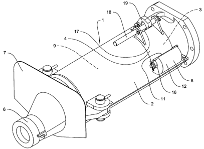
Figure 1 shows a perspective illustration of a tap hole
plug gun,
Figure 2 shows a side view of the tap hole plug gun,
Figure 3 shows an enlarged cross-sectional
illustration of the tap hole plug gun along
section line III-III of Figure 2 with the
closed position of the safety flap for the
plugging compound filling opening, and
Figure 4 shows an enlarged cross-sectional
illustration of the tap hole plug gun
corresponding to Figure 3 with the open
position of the safety flap.
The tap hole plug gun 1 has a pressure cylinder 2 having a
safety flap 4, which is pivotable in the arrow direction a
out of the closed position 4a into the open position 4b and
vice versa to open and close the filling opening 3 of the
pressure cylinder 2 for the plugging compound, a plugging
piston 5 for pressing the plugging compound out of a
mouthpiece 6, which is pressed against the tap hole of a

CA 02695269 2013-01-23
-3-
furnace, an electrohydraulic drive (not shown), for
example, for the plugging piston 5, and a protective shield
7, which is situated on the mouthpiece 6, against the
effect of heat and melted material exiting from the tap
hole of a furnace.
The pivotable safety flap 4 for closing the filling opening
3 of the pressure cylinder 2 for the plugging compound is
equipped with a stop 8, which, upon opening of the flap 4
by pivoting it in the arrow direction a into the open
position 4b, is pivoted into the cylinder chamber 9 of the
pressure cylinder 2 to decelerate an unintentional forward
stroke of the plugging piston 5 in the arrow direction c
for the pre-compression and expulsion of the plugging
compound, and upon closing of the safety flap 4 by pivoting
it in the arrow direction b into the closed position 4a, is
pivoted out of the cylinder chamber 9.
The safety flap 4 is implemented as curved corresponding to
the jacket 10 of the pressure cylinder 2 and engages
positively in the filling opening 3 of the pressure
cylinder 2 in the closed position 4a.
A roller segment 12, which is outwardly directed in the
closed position 4a of the safety flap, is situated on one
transverse side of 11 of the safety flap 4 and is pivoted
into the cylinder chamber 9 of the pressure cylinder 2 in
the open position 4b of this safety flap 4 and forms the
stop 8 for the plugging piston 5.
The roller segment 12 has a concentric bearing hole 13, for
example, for the pivot axis 15 of the safety flap 4, which
is oriented parallel to the central axis 14-14 of the
pressure cylinder 2 for receiving the plugging compound,
and the pivot axis 15 is mounted fixed in bearing eyes 16
on the jacket 10 of the pressure cylinder 2.

CA 02695269 2013-01-23
-4-
A rod-shaped handle 18, which is oriented parallel to the
central axis 14-14 of the pressure cylinder 2, is attached
in the area of the other transverse side 17 of the safety
flap 4, which is lockable in the closed position 4b of the
safety flap 4 using a hook 19 linked on the jacket 10 of
the pressure cylinder 2.

CA 02695269 2013-01-23
- 5 -
List of reference numerals
1 tap hole plug gun
2 pressure cylinder
3 filling opening
4 safety flap
4a closed position of 4
4b open position of 4
plugging piston
6 mouthpiece
7 protective shield
8 stop on 4
9 cylinder chamber of 2
jacket of 2
11 transverse side of 4
12 roller segment on 11
13 bearing hole in 12
14-14 central axis of 2
pivot axis of 4
16 bearing eye on 10
17 transverse side of 4
18 handle of 4
19 hook on 10
a pivot direction of 4
pivot direction of 4
forward stroke direction of 5

Representative Drawing
A single figure which represents the drawing illustrating the invention.
Administrative Status

For a clearer understanding of the status of the application/patent presented on this page, the site Disclaimer , as well as the definitions for Patent , Administrative Status , Maintenance Fee  and Payment History  should be consulted.

Administrative Status

Title Date
Forecasted Issue Date 2014-01-07
(22) Filed 2010-03-02
Examination Requested 2010-03-02
(41) Open to Public Inspection 2010-12-20
(45) Issued 2014-01-07
Deemed Expired 2015-03-02

Abandonment History

There is no abandonment history.

Payment History

Fee Type Anniversary Year Due Date Amount Paid Paid Date
Request for Examination $800.00 2010-03-02
Application Fee $400.00 2010-03-02
Maintenance Fee - Application - New Act 2 2012-03-02 $100.00 2012-02-13
Maintenance Fee - Application - New Act 3 2013-03-04 $100.00 2013-02-06
Final Fee $300.00 2013-10-29
Owners on Record

Note: Records showing the ownership history in alphabetical order.

Current Owners on Record
TMT TAPPING-MEASURING-TECHNOLOGY GMBH
Past Owners on Record
GOOSEN, JOHANNES JACOBUS
VINCENT, JOHN PAUL
Past Owners that do not appear in the "Owners on Record" listing will appear in other documentation within the application.
Documents

To view selected files, please enter reCAPTCHA code :


To view images, click a link in the Document Description column. To download the documents, select one or more checkboxes in the first column and then click the "Download Selected in PDF format (Zip Archive)" or the "Download Selected as Single PDF" button.

List of published and non-published patent-specific documents on the CPD .

If you have any difficulty accessing content, you can call the Client Service Centre at 1-866-997-1936 or send them an e-mail at CIPO Client Service Centre.


Document
Description 
Date
(yyyy-mm-dd) 
Number of pages   Size of Image (KB) 
Abstract 2010-03-02 1 25
Description 2010-03-02 5 154
Claims 2010-03-02 2 61
Drawings 2010-03-02 3 65
Representative Drawing 2010-11-24 1 13
Cover Page 2010-11-30 2 50
Claims 2013-01-23 2 56
Description 2013-01-23 5 138
Cover Page 2013-12-05 2 51
Assignment 2010-03-02 4 202
Prosecution-Amendment 2010-05-12 2 61
Prosecution-Amendment 2012-08-08 2 69
Prosecution-Amendment 2013-01-23 9 288
Correspondence 2013-10-29 2 68