Note: Descriptions are shown in the official language in which they were submitted.
CA 02695834 2010-03-04
DETECTING AND SENSING ACTUATION IN A CIRCUIT INTERRUPTING DEVICE
CROSS-REFERENCE TO RELATED APPLICATION
This application is a continuation-in-part of U.S. Patent Application Serial
No.
12/398,550 by Kamor et al. filed on March 5, 2009 entitled "DETECTING AND
SENSING ACTUATION IN A CIRCUIT INTERRUPTING DEVICE", the entire contents
of which is hereby incorporated by reference herein.
BACKGROUND
1. Field
The present disclosure relates to circuit interrupting devices. In particular,
the present
disclosure is directed to re-settable circuit interrupting devices and systems
that
comprises ground fault circuit interrupting devices (GFCI devices), arc fault
circuit.
interrupting devices (AFCI devices), immersion detection circuit interrupting
devices
(IDCI devices), appliance leakage circuit interrupting devices (ALCI devices),
equipment
leakage circuit interrupting devices (ELCI devices), circuit breakers,
contactors, latching
relays and solenoid mechanisms. More particularly, the present disclosure is
directed to
circuit interrupting devices that include a circuit interrupter that can break
electrically
conductive paths between a line side and a load side of the devices.
2. Description of the Related Art
Many electrical wiring devices have a line side, which is connectable to an
electrical
power supply, and a load side, which is connectable to one or more loads and
at least
one conductive path between the line and load sides. Electrical connections to
wires
supplying electrical power or wires'conducting electricity to the one or more
loads are at
line side and load side connections. The electrical wiring device industry has
witnessed
an increasing call for circuit breaking devices or systems which are designed
to interrupt
power to various loads, such as household appliances, consumer electrical
products
and branch circuits. In particular, electrical codes require electrical
circuits in home
bathrooms and kitchens to be equipped with circuit interrupting devices, such
as ground
fault circuit interrupting devices (GFCI), for example.
CA 02695834 2010-03-04
In particular, GFCI devices protect electrical circuits from ground faults
which may pose
shock hazards. To prevent continued operation of the particular electrical
device under
such conditions, a GFCI device monitors the difference in current flowing into
and out of
the electrical device. Load-side terminals provides electricity to the
electrical device.
A differential transformer measures the difference in the amount of current
flow through
the wires (i.e. - hot and neutral) disposed on the primary side (or core in
the case of a
toroid differential transformer) via a current signal analyzer, when the
difference in
current exceeds a predetermined level, e.g., 5 milliamps, indicating that a
ground fault
may be occurring, the GFCI device interrupts or terminates the current flow
within a
particular time period, e.g., 25 milliseconds or greater. The current may be
interrupted
via a solenoid coil that mechanically opens switch contacts to. shut down the
flow of
electricity. A GFCI device includes a reset button that allows a user to reset
or close the
switch contacts to resume current flow to the electrical device. A GFCI device
may also
include a user-activated test button that allows the user to activate or trip
the solenoid to
open the switch contacts to verify proper operation of the GFCI.device.
Presently available GFCI devices, such as the device described in U.S. Pat.
No.
4,595,894 (the '894 patent) which is incorporated herein in its entirety by
reference, use
an electrically activated trip mechanism to mechanically break an electrical
connection
between the line side and the load side. Such devices are resettable after
they are
tripped by, for example, the detection of a ground fault. In the device
discussed in the
'894 patent, the trip mechanism used to cause the mechanical breaking of the
circuit
(i.e., the conductive path between the line and load sides) includes a
solenoid (or trip
coil). A test button is used to test the trip mechanism and circuitry used to
sense faults,
and a reset button is used to reset the electrical connection between line and
load
sides.
In addition, intelligent ground fault circuit interrupting (IGFCI) devices are
known in the
art that can automatically test internal circuitry on a periodic basis. Such
GFCI devices
can perform self-testing on a monthly, weekly, daily or even hourly basis. In
particular,
all key components can be tested except for the, relay contacts. This is
because tripping
the contacts for testing has the undesirable result of removing power to the
user's
2
CA 02695834 2010-03-04
circuit. However, once a month, for example, such GFCI devices can generate a
visual
and/or audible signal or alarm reminding the user to manually test the GFCI
device. The
user, in response to the signal, initiates a test by pushing a test button,
thereby testing
the operation of the contacts in addition to the rest of the GFCI circuitry.
Following a
successful test, the user can reset the GFCI device by pushing a reset button.
Examples of such intelligent ground fault circuit interrupter devices can be
found in U.S.
Patent 5,600,524, U.S. Patent 5,715,125, and U.S. Patent 6,111,733 each by
Nieger et
al. and each entitled "INTELLIGENT GROUND FAULT CIRCUIT INTERRUPTER," and
1o each of which is incorporated herein by reference in its entirety.
Additionally, another
example of an intelligent ground fault current interrupter device can be found
in U.S.
Patent 6,052,265 by Zaretsky et at., entitled "INTELLIGENT GROUND FAULT
CIRCUIT
INTERRUPTER EMPLOYING MISWIRING DETECTION AND USER TESTING," which
is incorporated herein by reference in its entirety.
SUMMARY
The present disclosure is directed to detecting and sensing solenoid plunger
movement
in a current interrupting device. In particular, the present disclosure
relates to a circuit
interrupting device that includes a first conductor, a second conductor, a
switch between
the first conductor and the second conductor wherein the switch is disposed to
selectively connect and disconnect the first conductor and the second
conductor, a
circuit interrupter disposed to generate a circuit interrupting actuation
signal, a solenoid
coil and plunger assembly. disposed to open the switch wherein the solenoid
coil and
plunger assembly is actuatable by the circuit interrupting actuation signal
wherein
movement-of the plunger causes the switch to open,and a test assembly that is
configured to enable a test of the circuit interrupter initiating at least a
partial movement
of the plunger in a test direction, from a pre-test configuration to a post-
test
configuration, without opening the switch.
3o The present disclosure relates also to a method of testing a circuit
interrupting device
that includes the steps of: generating an actuation signal; causing a plunger
to move in
response to the actuation signal, without causing a switch, that when in the
closed
position enables flow of electrical current through said circuit interrupting
device, to
3
CA 02695834 2010-03-04
open; measuring the movement of the plunger; and determining whether the
movement
reflects at least a partial movement of the plunger in a test direction, from
a pre-test
configuration to a post-test configuration, without opening the switch.
BRIEF DESCRIPTION OF THE DRAWINGS
Various embodiments of the present disclosure are described herein with
reference'to
the drawings wherein:
FIG. 1 is a perspective view of one embodiment of a circuit interrupting
device
according to the present disclosure;
FIG. 2 is a top view of a portion of the circuit interrupting device according
to the present
disclosure shown in FIG. 1, with the face portion removed;
FIG. 3 is an exploded perspective view of the face terminal internal frames,
load
terminals and movable bridges;
FIG. 4 is a perspective view of the arrangement of some of the components of
the
circuit interrupter of the device of FIGS. 1-3 according to the present
disclosure;
FIG. 5 is a side view of FIG. 4;
FIG. 6 is a simplified perspective view of a test assembly of a circuit
interrupting device
according to the present disclosure in a pre-test configuration having at
least one
sensor that is not in contact with a solenoid plunger in the pre-test
configuration;
FIG. 7 is a simplified perspective view of the test assembly of the circuit
interrupting
device of FIG. 7 in a post-test configuration having at least one sensor that
is in contact
with the solenoid plunger in the post-test configuration;
3o FIG. 8 is a simplified perspective view of a test assembly of a circuit
interrupting device
according to the present disclosure in a pre-test configuration having at
least one
sensor that is in contact with a solenoid plunger in the pre-test
configuration;
4
CA 02695834 2010-03-04
FIG. 9 is a simplified perspective view of the test assembly of the circuit
interrupting
device of FIG. 8 in a post-test configuration having at least one sensor that
is not in
contact with the solenoid plunger in the post-test configuration;
FIG.10 is a perspective view of one embodiment of a part of a circuit
interrupting device
that is configured with a piezoelectric member to detect and sense solenoid
plunger
movement according to the present disclosure;
FIG. 11 is a perspective view of one embodiment of a part of a circuit
interrupting device
that is configured with a resistive member to detect and sense solenoid
plunger
movement according to the present disclosure;
FIG. 12 is a perspective view of one embodiment of a part of a circuit
interrupting device
that is configured. with a capacitive member to detect and sense solenoid
plunger
movement according to the present disclosure;
FIG. 13 is a perspective view of one embodiment of a part of a circuit
interrupting device
that is configured with conductive members forming a conductive path to detect
and
sense solenoid plunger movement according to the present disclosure;
FIG. 14 is a simplified perspective view of a test assembly of a circuit
interrupting device
according to the present disclosure in a pre-test configuration wherein a
solenoid
plunger is in a position with respect to at least one sensor in a pre-test
configuration;
FIG. 15 is a simplified perspective view of the test assembly of the circuit
interrupting
device of FIG. 14 wherein the solenoid plunger is in another position with
respect to at
least one sensor in a post-test configuration;
FIG. 16 is a perspective view of one embodiment of a part of a circuit
interrupting device
that is configured with conductive members providing capacitance to detect and
sense
solenoid plunger movement according to the present disclosure; and
5
CA 02695834 2010-03-04
FIG. 17 is a perspective view of one embodiment of a part of a circuit
interrupting device
that is configured with an optical emitter and an optical sensor to detect and
sense
solenoid plunger movement according to the present disclosure.
FIG. 18 is a perspective view of one embodiment of a part of a circuit
interrupting device
having a coil and plunger assembly according to the present disclosure wherein
the
plunger is magnetic or contains a magnet;
FIG. 19 is a cross-sectional view of the coil and plunger assembly of FIG. 18
illustrating
to the plunger that is magnetic or includes a magnet;
FIG. 20 is a perspective view of one embodiment of a part of a circuit
interrupting device
according to the present disclosure wherein the coil of the circuit
interrupting device is
pulsed for a brief period of time so as to result in a partial forward
movement of the
plunger but less than that required to open the circuit interrupting switch;
FIG. 21 is a perspective view of one embodiment.of a part of a circuit
interrupting device
according to the present disclosure wherein a sensor such as a piezoelectric
element
generates a test sensing signal indicating movement of the plunger upon
sensing an
acoustic signal generated by actuation and movement of the plunger;
FIG. 22 is a perspective view of one embodiment of a part of a circuit
interrupting device
according to the present disclosure wherein a magnetic reed switch generates a
test
sensing signal indicating movement of the plunger upon sensing a magnetic
field
generated by actuation and movement of the plunger;
FIG. 23 is a perspective view of one embodiment of a part of a circuit
interrupting device
according to the present disclosure wherein a Hall-effect sensor generates a
test
sensing signal indicating movement of the plunger upon sensing a magnetic
field
generated by actuation and movement of the plunger;
FIG. 24 is a perspective view of one embodiment of a part of a circuit
interrupting device
according to the present disclosure that includes, in addition to a circuit
interrupting coil,
6
CA 02695834 2010-03-04
at least one test coil wherein the orifice of the test coil and the orifice of
the circuit
interrupting coil are disposed wherein the plunger moves to and from the
respective
orifices upon electrical actuation of the test coil;
FIG. 25 is a perspective view of the test coil and the circuit interrupting
coil of the circuit
interrupting device of FIG. 24;
FIG. 26 is across-sectional view of the test coil and the circuit interrupting
coil of the
circuit interrupting device of FIG. 24;
FIG. 27 is a perspective view of one embodiment of a part of a circuit
interrupting device
according to the present disclosure that includes, in addition to a circuit
interrupting coil,
at least one test coil wherein the orifice of the coils are aligned and joined
at a common
joint so as to enable the plunger to move in the orifices between the coils;
FIG. 28 is a perspective view of the test coil and the circuit interrupting
coil of the circuit
interrupting device of FIG. 27;
FIG. 29 is a cross-sectional view of the test coil and the circuit
interrupting coil of the
circuit interrupting device of FIG. 27;
FIG.30 is a perspective view of one embodiment of a part of a circuit
interrupting device
according to. the present disclosure that includes, in addition to a circuit
interrupting coil,
at least one test coil wherein the test coil is concentrically disposed around
the circuit
interrupting coil such that the plunger moves through the orifice the circuit
interrupting
coil while the test coil measures a change in inductance;
FIG. 31 is a cross-sectional view of the circuit interrupting coil and the
test coil of FIG.
30;
FIG. 32 is a perspective view of one.embodiment of a part of a circuit
interrupting device
according to the present disclosure that includes, in addition to a circuit
interrupting coil,
at least one test coil wherein the test coil is concentrically disposed around
the circuit
7
CA 02695834 2010-03-04
interrupting coil such that the plunger moves through the orifice the circuit
interrupting
coil while the test coil measures a change in inductance and wherein the
plunger is
magnetic or includes a magnet;
FIG. 33 is a cross-sectional view of the circuit interrupting coil and the
test coil of FIG.
32;
FIG. 34 is a perspective view of one embodiment of a part of a circuit
interrupting device
in which a moving mechanism interferes with travel of the plunger to prevent
the plunger
from actuating the GFCI device during a transfer from a pre-test configuration
or non-
actuated configuration to a post-test configuration;
FIG. 35 is a cross-sectional view of one embodiment of a part of a circuit
interrupting
device according to FIG. 34 in a pre-test or non-actuated configuration in
which the
moving mechanism maintains a rotating member in a position that does not
interfere
with movement of the plunger in the pre-test or non-actuated configuration;
FIG. 36 is a cross-sectional view of the circuit interrupting device according
to FIG. 35 in
a post-test configuration illustrating the moving mechanism driving the
rotating member
to interfere with movement of the plunger in the post-test configuration;
FIG. 37 is a cross-sectional view of the circuit interrupting device according
to FIG. 35 in
a fault actuation configuration in which the moving mechanism maintains the
rotating
member in a position that does not interfere with movement of the plunger in
the fault
-actuation configuration;
FIG. 38 is a cross-sectional view of one embodiment of a part of a circuit
interrupting
device according to FIG. 34 in a pre-test or non-actuated configuration in
which the
moving mechanism maintains a translating member in a position that does not
interfere
3o with movement of the plunger in the pre-test or non-actuated configuration;
FIG. 38A is view of the translating member in the pre-test or non-actuated
configuration
as viewed from direction 38A of FIG. 38;
8
CA 02695834 2010-03-04
FIG. 38B is side view of the translating member and a portion of the moving
mechanism
of FIG. 38A;
FIG. 39 is a cross-sectional view of the circuit interrupting device according
to FIG. 38 in
a- post-test configuration illustrating the moving mechanism driving the
translating
member to interfere with movement of the plunger in the post-test
configuration; and
FIG. 40 is a cross-sectional view of the circuit interrupting device according
to FIG. 38 in
1o a fault actuation configuration in which the moving mechanism maintains the
translating
member in a position that does not interfere with movement of the plunger in
the fault
actuation configuration.
DETAILED DESCRIPTION
The present disclosure relates to a current interrupting device configured to
perform an
automatic self-test sequence on a periodic basis (e.g., - every few cycles of
alternating
current (AC), hourly, daily, weekly, monthly, or other suitable time period)
without the
need for user intervention and, in addition, wherein the current interrupting
device
includes members configured to enable the self-test sequence or procedure to
test the
operability and functionality of the device's components up to and including
the
movement of the solenoid plunger.
The description herein is described with reference to a ground fault circuit
interrupting
(GFCI) device for exemplary purposes. However, aspects of the present
disclosure are
applicable to other types of circuit interrupting devices, such as arc fault
circuit
interrupting devices (AFCI devices), immersion detection circuit interrupting
devices
(IDCI devices), appliance leakage circuit interrupting devices (ALCI devices),
equipment
leakage circuit interrupting devices (ELCI devices), circuit breakers,
contactors, latching
3o relays and solenoid mechanisms.
As defined herein, the terms forward, front, etc. refers to the direction in
which the
standard plunger moves in order to trip the GFCI. Terms such as front,
forward, rear,
9
CA 02695834 2010-03-04
back, backward, top, bottom, side, lateral, transverse, upper, lower and
similar terms
are used solely for convenience of description and the embodiments of the
present
disclosure are not limited thereto.
As defined herein, a test assembly includes features added herein to a circuit
interrupting device to effect the movement of the plunger and detect the
movement
thereof or to effect actuation of the solenoid coil and to detect actuation
thereof (e.g., via
a non-contact switch such as a reed switch or a Hall-effect sensor). Such
features may
include, but are not limited to, electrical or optical circuitry, sensors
(including
mechanical, electrical, optical or acoustical), magnets, or stationary or
movable support
members such as support surfaces or partitions, or the like, that facilitate
and/or enable
performance of an automatic self-test sequence on a periodic basis of a
circuit
interrupting device without the need for user intervention.
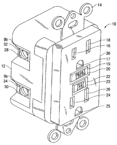
Turning now to FIG. 1, an exemplary GFCI device 10, which may be configured to
perform an automatic self-test sequence on a periodic basis as described above
without
the need for user intervention. The self-test sequence tests the operability
and
functionality of the GFCI components up to and including the movement of the
solenoid
according to the present disclosure. GFCI device 10 has a housing 12 to which
a face
or cover portion 36 is removably secured. The face portion 36 has entry ports
or
openings 16, 18, 24 and 26 aligned with contacts for receiving normal or
polarized
prongs of a male plug of the type normally found at the end of a household
device
electrical cord (not shown), as well as ground-prong-receiving openings 17 and
25 to
accommodate three-wire plugs. The GFCI device 10,also includes a mounting
strap 14
used to fasten the device to a junction box.
A description of such a circuit interrupting device can be found in U.S.
Patent
Application Publication US 2004/0223272 Al, by Germain et al., entitled
"CIRCUIT
INTERRUPTING DEVICE AND SYSTEM UTILIZING BRIDGE CONTACT
MECHANISM AND RESET LOCKOUT," the entire contents of which are incorporated
herein by reference.
CA 02695834 2010-03-04
A test button 22 extends through opening 23 in the face portion 36 of the
housing 12.
The test button 22 is used when it is desired to manually trip the device 10.
The circuit
interrupter, to be described in more detail below, breaks electrical
continuity in one or
more conductive paths between the line and load side of the device. The one or
more
conductive paths form a power circuit in the GFCI 10. A reset button 20
forming a part
of the reset portion extends through opening 19 in the face portion 36 of the
housing 12.
The reset button 20 is used to activate a reset operation, which reestablishes
electrical
continuity through the conductive paths.
1o Still referring to FIG. 1, electrical connections to existing household
electrical Wiring are
made via binding screws 28 and 30 where, for example, screw 30 is an input (or
line)
phase connection, and screw 28 is an output (or load) phase connection. Screws
28
and 30 are fastened (via a threaded arrangement) to terminals 32 and 34
respectively.
However, the GFCI device 10 can be designed so that screw 30 can be an output
phase connection and screw 28 an input phase or line connection. Terminals 32
and 34
are one half of terminal pairs. Thus, two additional binding screws and
terminals (not
shown) are.located on the opposite side of the device 10. These additional
binding
screws provide line and load neutral connections, respectively. It should also
be noted
that the binding screws and terminals are exemplary of the types of wiring
terminals that
can be used to provide the electrical connections. Examples of other types of
wiring
terminals include set screws, pressure clamps, pressure plates, push-in type
connections, pigtails and quick- connect tabs. The face terminals are
implemented as
receptacles configured to mate with male plugs. A detailed depiction of the
face
terminals is shown in FIG. 2.
For the purposes of describing embodiments of the circuit interrupter
according to the
present disclosure, the terminal 34 (and its corresponding terminal on the
opposite side
of the device 10 that is not shown) form a first conductor or line conductor
9a while the
terminal 32 (and its corresponding terminal on the opposite side of the device
10 that is
3o not shown) form a second conductor or load conductor 9b.
Referring to FIG. 2, a top view of the GFCI device 10 (without face portion 36
and strap
14) is shown. An internal housing structure 40 provides the platform on which
the
11
CA 02695834 2010-03-04
components of the GFCI device are positioned. Reset button 20 and test button
22 are
mounted on housing structure 40. Housing structure 40 is mounted on printed
circuit
board 38. The receptacle aligned to opening 16 of face. portion 36 is made
from
extensions 50A and 52A of frame 48.
Frame or contact 48 is made from an electricity conducting material from which
the
receptacles aligned with openings 16 and 24 are formed. The receptacle aligned
with
opening 24 of face portion 36 is constructed from extensions 50B and 52B of
frame 48.
Also, frame 48 has a flange the end of which has. electricity conducting
contact 56
attached thereto. Frame 46 is made from an electricity conducting material
from which
contacts aligned with openings 18 and 26 are formed.
The contact aligned with opening 18 of frame portion 36 is constructed with
frame
extensions 42A and 44A. The contact aligned with opening 26 of face portion 36
is
constructed with extensions 42B and 44B. Frame 46 has a flange the end of
which has
electricity conducting contact 60 attached thereto. Therefore, frames 46 and
48 form the
face terminals implemented as contacts aligned to openings 16, 18, 24 and 26
of face
portion 36 of GFCI 10 (see FIG. 1). Load terminal 32 and line terminal 34 are
also
mounted on internal housing structure 40. Load terminal 32 has an extension
the end of
which electricity conducting load contact 58 is attached. Similarly, load
terminal 54 has
an extension to which electricity conducting contact 62 is attached. The line,
load and
face terminals are electrically isolated from each other and are electrically
connected to
each other by a pair of movable bridges. The relationship between the line,
load and
face terminals and how they are connected to each other is shown in FIG. 3.
Other
configurations of line, load and face conductive paths and their points of
connectivity,
with and without movable bridges are well known and within the scope of this
disclosure.
Referring now to FIG. 3, there is shown the positioning of the face and load
terminals
with respect to each other and their interaction with the movable bridges (64,
66).
Although the line terminals are not shown, it is understood that they are
electrically
connected to one end of the movable bridges. The movable bridges (64, 66) are
generally electrical conductors that are configured and positioned to connect
at least the
12
CA 02695834 2010-03-04
line terminals to the load terminals. In particular movable bridge 66 has an
arm portion
66B and a connecting portion 66A that are formed at an angle to each other
(approximately 90 degrees in the exemplary embodiment illustrated in FIGS. 2-
5). Arm
portion 66B is electrically connected to line terminal 34 (not shown).
Similarly, movable bridge 64 has an arm portion 64B and a connecting portion
64A that
are also formed at an angle to each other (approximately 90 degrees in the
exemplary
embodiment illustrated in FIGS. 2-5). Arm portion 64B is electrically
connected to the
other line terminal (not shown); the other line terminal being located on the
side
opposite that of line terminal 34. Connecting portion 66A of movable bridge 66
has two
fingers each having a bridge contact (68, 70) attached to its end. Connecting
portion
64A of movable bridge 64 also has two fingers each of which has a bridge
contact (72,
74) attached to its end. The bridge contacts (68, 70, 72 and 74) are made from
conductive material. Also, face terminal contacts 56 and 60 are made from
conductive
material. Further, the load terminal contacts 58 and 62 are made from
conductive
material. The movable bridges 64, 66 are preferably made from flexible metal
that can
be flexed when subjected to mechanical forces.
The connecting portions (64A, 66A) of the movable bridges 64, 66,
respectively, are
mechanically biased downward or in the general direction shown by arrow 67.
When
the GFCI device 10 is reset, the connecting portions of the movable bridges
are caused
to move in the direction shown by arrow 65 and engage the load and face
terminals
thus connecting the line, load and face terminals to each other.
In particular connecting portion 66A of movable bridge 66 is formed at an
angle with
respect to arm portion 66B to face in an upward direction (direction shown by
arrow 65)
to allow contacts 68 and 70 to engage contacts 56 of frame 48 and contact 58
of load
terminal 32 respectively. Similarly, connecting portion 64A of movable bridge
64 is
formed at an angle with respect to prong portion 64A to face in an upward
(direction
shown by arrow 65) to allow contacts 72 and 74 to engage contact 62 of load
terminal
54 and contact 60 of frame 46 respectively. The connecting portions 64A, 66A
of the
movable bridges 64., 66 are moved in an upwards direction by a latch/lifter
assembly
positioned underneath the connecting portions where this assembly moves in an
13
CA 02695834 2010-03-04
upward direction (direction shown by arrow.65) when the GFCI device is reset.
It
should be noted that the contacts of a movable bridge engaging a contact of a
load or
face terminals occurs when electric current flows between the contacts; this
is done by
having the contacts touch each other. Some of the components that cause the
connecting portions of the movable bridges to move upward are shown in FIG. 4.
For the purposes of describing embodiments of the circuit interrupter
according to the
present disclosure, referring again also to FIG. 1, the bridge contacts 68 and
70,
engaging contacts 56 of frame 48 and contact 58 of load terminal 32,
respectively, and
1o bridge contacts 72 and 74, engaging contact 62 of load terminal 54 and
contact 60 of
frame 46, respectively, are defined herein collectively as a circuit
interrupting switch 11
between the first conductor or line conductor 9a and the second conductor or
load
conductor 9b.
Referring again also to FIG. 2, FIGS. 4 and 5 illustrate a partial view of the
GFCI device
10 according to the present disclosure that is configured to perform an
automatic self-
test sequence on a periodic basis that includes movement of.a solenoid
plunger. More
particularly, the GFCI device 10 includes a fault sensing circuit residing in
a printed
circuit board 38. The fault sensing circuit is not explicitly shown in FIGS.
2, 4 or 5 and is
incorporated into the layout of the printed circuit board 38. Components for
the circuit
are electrically coupled to the printed circuit board 38 which receives
electrical power
from the power being supplied externally to the GFCI device 10. The fault
sensing
circuit is configured to detect a predetermined condition and to generate a
circuit
interrupting actuation signal. FIG. 4 illustrates mounted on printed circuit
board 38 a
fault circuit interrupting solenoid coil and plunger assembly or combination 8-
that
includes bobbin 82 having a cavity 50 in which elongated cylindrical plunger
80 is
slidably disposed. For clarity of illustration, frame 48 and load terminal 32
are not
shown.
One end 80a of plunger 80 is shown extending outside of the bobbin cavity 50.
The
other end of plunger 80 (not shown) is coupled to or engages a spring that
provides the
proper force for pushing a portion of the plunger 80 outside of the bobbin
cavity 50 after
the plunger 80 has been pulled into the cavity 50 due to a resulting magnetic
force when
14
CA 02695834 2010-03-04
the coil is energized. Electrical wire is wound around bobbin 82 to form a
coil of the
combination solenoid coil and plunger assembly 8. Although for clarity of
illustration the
coil wire wound around bobbin 82 is not shown in FIGS. 4 and 5, reference
numeral 82
in those figures refer to the coil wire forming a coil 82. Further, reference
number 82 in
FIGS. 10-13 and 16-17 refers to the coil wire or coil wound around the bobbin.
Accordingly, the fault circuit interrupting coil and plunger assembly 8
(hereinafter
referred to as coil and plunger assembly 8 or combination coil and plunger
assembly 8)
has at least one coil 82 and is actuatable by the circuit interrupter
actuation signal
generated by the fault sensing circuit and is configured to cause electrical
discontinuity
of power supplied to a load (not shown) by the GFCI device 10 via actuation by
the fault
sensing circuit upon detection of the occurrence of the predetermined
condition.
A lifter 78 and latch 84 assembly is shown where the lifter 78 is positioned
underneath
the movable bridges. The movable bridges 66 and 64 are secured with mounting
brackets 86 (only one is shown) which is also used to secure line terminal 34
and the
other line terminal (not shown) to the GFCI device 10. It is understood that
the other
mounting bracket 86 used to secure movable bridge 64 is positioned directly
opposite
the shown mounting bracket. The reset button 20 has a reset pin 76 which
engages
lifter 78 and latch 84 assembly.
FIG. 5 illustrates a side view of the GFCI device 10 of FIG. 4. Prior to the
coil 82 being
energized, the GFCI device 10 is in a non-actuated configuration. Upon the
detection of
the occurrence of the predetermined condition, fault sensing circuit assumes
that a real
transfer of the GFCI device 10 from the non-actuated configuration to an
actuated
configuration is required such that the plunger 80 will move in a fault
direction, i.e., the
direction necessary for the plunger 80 to move a distance sufficient to cause
disengagement of at least one set of contacts, as described below, and thereby
cause
electrical discontinuity along a conductive path, i.e., causing the GFCI
device 10 to trip.
More particularly, when the circuit interrupting actuation signal causes the
coil 82 to be
energized, plunger 80 is pulled into the coil in the direction shown by arrow
81. The
direction shown by arrow 81 is referred to herein as the fault direction 81 of
the plunger
80. Connecting portion 66A of movable bridge 66 is shown biased downward (in
the
CA 02695834 2010-03-04
direction shown by arrow 85). Although not shown, connecting portion of
movable
bridge 64 is similarly biased. Also part of a mechanical switch--test arm 90--
is shown
positioned under a portion of the lifter 78. It should be noted that because
frame 48 is
not shown, face terminal contact 56 is also not shown.
Thus, referring again to FIGS. 2-5, the GFCI device 10 includes a circuit
interrupter 10'
that is configured to cause electrical discontinuity in the GFCI device 10
upon the
occurrence of at least one predetermined condition. The circuit interrupter
10' includes
the switch 11, defined herein as the at least a set of contacts, e.g., bridge
contacts 72,
74 (of movable bridge 64) and 68, 70 (of movable bridge 66), that are
configured
wherein disengagement of at least one of the sets of contacts, e.g., 72 and 74
or 68 and
70, enables the electrical discontinuity along a conductive path in the GFCI
device 10.
More particularly, the switch 11 is disposed to selectively connect and
disconnect the
first conductor or line conductor 9a and the second conductor or load
conductor 9b.
The circuit interrupter 10' also includes the fault sensing circuit failure
sensing circuit
that may reside in the printed circuit board 38, and that is configured to
detect the
predetermined condition and to generate a circuit interrupting actuation
signal.
Additionally, the circuit interrupter 10' includes at least the coil and
plunger assembly 8
having the coil 82 and the plunger 80 that are actuatable by the circuit
interrupting
actuation signal and are configured and disposed wherein movement of the
plunger 80
causes the electrical discontinuity via disengagement of at least one of the
sets of
contacts, e.g., 72 and 74 or 68 and 70, from each other upon detection of the
occurrence of the predetermined condition. In other words, the circuit
interrupter 10' is
disposed to generate the circuit interrupting actuation signal upon detection
of the
predetermined condition. The coil and plunger assembly 8 is adapted to be
actuatable
by the circuit interrupting actuation signal wherein movement of the plunger
80 causes
the switch 11 to open.
As defined above and as defined in greater detail below, a test assembly
according to
the embodiments of the present disclosure is configured to enable a test of
the circuit
interrupter 10', to initiate at least a partial movement of the plunger 80 in
a test direction,
from a pre-test configuration to a post-test configuration, without opening
the switch 11.
16
CA 02695834 2010-03-04
Referring also to FIGS. 6-17, GFCI device 10 also includes a test assembly 100
that is
configured to enable an at least partial operability self test of the GFCI
device 10,
without user intervention, to initiate movement of the plunger 80 from a pre-
test
configuration to a post-test configuration by testing operability of the coil
and plunger
assembly 8 and of the consequential capability of the fault sensing circuit to
effect
movement of the plunger 80, including detection of a fault in the coil 82 that
is separate
from the capability of the plunger 80 to move from a pre-test configuration to
a post-test
configuration. That is, the circuit interrupting test assembly 100 is
configured to enable
a test of the circuit interrupter 10, e.g., the GFCI device, to initiate or to
cause at least
1o partial movement of the plunger 80 without opening the switch 11.
As explained in more detail below'with respect to FIGS. 6-17, the test
assembly 100,
alternatively referred to as a circuit interrupting test assembly, includes a
test initiation
circuit that is configured to initiate and conduct an at least partial test of
the circuit
interrupter 10', that is, a test of the ability of the circuit interrupter 10'
to perform its
intended function of causing electrical discontinuity in the GFCI device 10,
e.g., a test of
the circuit interrupting device 10 that includes initiating movement of the
plunger 80 from
a pre-test configuration to a post-test configuration. The test assembly 100
also
includes a test sensing circuit that is configured to sense a result of the at
least partial
test of the circuit interrupter 10' or GFCI device 10. The test assembly 100
is configured
to enable an at least partial test of the circuit interrupter 10' by testing
at least partially
movement of the plunger 80 without disengagement of the contacts such as
contacts 72
and 74, and 68 and 70. That is, the test assembly 100 is configured to cause
the
plunger 80 to move, from a pre-test configuration, in a test direction, e.g.,
test direction
83 or alternate test direction 83', to a post-test configuration, a distance
that is
insufficient to disengage the at least one set of contacts, e.g., contacts 72
and 74, and
68 and 70, from each other, thereby causing electrical discontinuity along a
conductive
path in the GFCI device 10.
3o As defined herein, insufficient movement includes either no detectable
movement of the
plunger or movement of the plunger that is not sufficient to disengage the at
least a set
of contacts during a required real transfer of the circuit interrupting device
from the non-
17
CA 02695834 2010-03-04
actuated configuration to the actuated configuration, the actuated
configuration resulting
in a trip of the GFCI device 10.
Unless otherwise noted, the non-actuated configuration and the pre-test
configuration of
the GFCI device 10 are equivalent. However, since the actuated configuration
of the
GFCI device 10 occurs following a real transfer of the GFCI device 10 from the
non-
actuated configuration, during which time power is supplied to the load side
connections
through a conductive path in the GFCI device 10, to the actuated
configuration, and
thus involves causing the plunger 80 to move a distance sufficient to
disengage the at
least one set of contacts, e.g., contacts 72 and 74, and 68 and 70, the
actuated
configuration differs from the post-test configuration.
The post-test configuration as defined herein is not a static configuration of
the GFCI
device 10 but is a transitory state that occurs over a period of time
beginning with the
initiation of the test actuation signal and ending with the resultant final
plunger
movement, or lack thereof depending on the results of the test.
To support the detecting and sensing members of the test assembly 100 of the
present
disclosure, GFCI device 10 also includes a rear support member 102 that is
positioned
or disposed on the printed circuit board 38 and with respect to the cavity 50
so that one
surface 102' of the rear support member 102 may be in interfacing relationship
with the
first end 80a of the plunger 80 and may be substantially perpendicular or
orthogonal to
the.movement of the plunger 80 as indicated by arrow 81.
Additionally, first and second lateral support members 104a and 104b,
respectively, are
positioned or disposed on the printed circuit board 38 and with respect to the
cavity 50
so that one surface 104a' and 104b' of first and second lateral support
members 104a
and 104b, respectively, may be substantially parallel to the movement of the
plunger 80
as indicated by arrow 81 and is in interfacing relationship with the plunger
80. Thus, the
rear support member 102 and the first and second lateral support members 104a
and
104b, respectively, partially form a box-like configuration partially around
the plunger 80.
The rear support member 102 and the first and second lateral support members
104a
and 104b, respectively, may be unitarily formed together or be separately
disposed or
18
CA 02695834 2010-03-04
positioned on the circuit board 38. The printed circuit board 38 thus serves
as a rear or
bottom support member for the combination solenoid coil and plunger that
includes the
coil or bobbin 82 and the plunger 80.
In conjunction with FIGS. 2-5, while referring particularly to FIGS. 6-7,
there is illustrated
a view of the test assembly 100 wherein at least one sensor 1000 of the test
assembly
100 is disposed wherein, when the circuit interrupter 10' is in a pre-test
configuration,
e.g., pre-test configuration 1001a as illustrated in FIG. 6, the plunger 80 is
not in contact
with the at least one sensor 1000. When the circuit interrupter 10' is in a
post-test
1o configuration, e.g., post-test configuration 1001 b as illustrated in FIG.
7, the plunger 80
is in contact with the at least one sensor 1000. Thus the at least one sensor
1000 is
disposed to detect a change in position of the plunger 80 from the pre-test
configuration
1001 a to the post-test configuration 1001 b. As illustrated in FIGS. 6-7, the
test
assembly 100 is configured to cause the plunger 80 to move in a test direction
83 that is
different from the fault direction 81, and more particularly as illustrated,
in a test
direction 83 that is opposite to the fault direction 81.
In an alternate embodiment, at least one sensor 1000' of the test assembly 100
is
disposed at a position with respect to the plunger 80 such that when the
circuit
interrupter 10' transfers from the pre-test configuration 1001a (see FIG. 6)
to the post-
test configuration 1001b (see FIG. 7), the test assembly 100 is thus
configured to cause
the plunger 80 to move in a test direction 83' that is in the same direction
as the fault
direction 81.
In an alternate embodiment, referring to FIGS. 8-9, again in conjunction with.
FIGS. 2-5,
there is illustrated a simplified view of the test assembly 100 wherein at
least one
sensor 1000 of the test assembly 100 is disposed wherein, when the circuit
interrupter
10' is in a pre-test configuration, e.g., pre-test configuration 1002a as
illustrated in FIG.
8, the plunger 80 is in contact with the at least one sensor 1000. When the
circuit
interrupter 10' is in a post-test configuration, e.g., post-test configuration
1002b as
illustrated in FIG. 9, the plunger 80 is not in contact with the at least one
sensor 1000.
Thus, in a similar manner as with respect to FIGS. 6-7, the at least one
sensor 1000 is
disposed to detect a change in position of the plunger 80 from the pre-test
configuration
19
CA 02695834 2010-03-04
1002a to the post-test configuration 1002b. As illustrated in FIGS. 6-7, the
test
assembly 100 is configured to cause the plunger 80 to move in test direction
83' that is
in the same direction as the fault direction 81.
As discussed in more detail below, the one or more sensors 1000 or 1000' may
include
at least one electrical element.
FIG. 10 illustrates one embodiment of the present disclosure wherein the test
assembly
100 of the GFCI device 10 is defined by a test assembly 100a wherein at least
one
1o sensor includes an electrical element that is in contact with the plunger
80 when the
GFCI device 10 is in a pre-test configuration. More particularly, test
assembly 100a
includes as at least one electrical element at least one piezoelectric member
110, e.g. a
pad or a sensor, having. a surface 110' that is disposed on the surface 102'
of the rear
support member 102 so that the surface 102' is in interfacing relationship
with the first
end 80a of the plunger 80. The combination solenoid coil and plunger assembly
8 is
disposed on the printed circuit board 38 with respect to the piezoelectric
member 110 so
that when the GFCI device 10a is.in the pre-test configuration exemplified by
pre-test
configuration 1002a illustrated in FIG. 8, the first end 80a of the plunger 80
is in
substantially stationary contact with the surface 110' so that substantially
no
measurable voltage is produced by the piezoelectric member 110. When the
plunger
80 is not in contact with the piezoelectric member 110, the piezoelectric
member 110
produces substantially no voltage. In the exemplary embodiment illustrated in
FIG. 10,
as noted above, the circuit interrupter 10' is in the pre-test configuration
1002a
illustrated in FIG. 8.
A voltage sensor 112 is electrically coupled to the piezoelectric sensor 110
via first and
second connectors/connector terminals 1 12a and 1 12b, respectively. The test
assembly 100a of the GFCI device 1Oa further includes a test initiation
circuit and a test
sensing circuit, which are illustrated schematically as a combined self-test
initiation and
sensing circuit 114, although the test initiation features and the sensing
features can be
implemented.by a separate test initiation circuit and a separate test sensing
circuit. The
voltage sensor 112 is also electrically coupled to the sensing features of the
circuit 114.
CA 02695834 2010-03-04
Due to the physical characteristics of piezoelectric members such as the
piezoelectric
member 110, a voltage is only output from the piezoelectric member 110 when it
is
dynamically contacted by a separate object, e.g., plunger 80, traveling with a
velocity
sufficient to cause an impact force or pressure to produce a measurable
voltage output
that is indicative of prior movement of the plunger 80 away from, and re-
contact of the
plunger 80 with, the piezoelectric member 110.
Thus, the GFCI device 10a has a three-stage post-test configuration. In the
first stage
of the post-test configuration, the GFCI device 1 Oa assumes the post-test
configuration
1002b illustrated in FIG. 9, wherein the plunger 80 moves away from the
piezoelectric
member 110, represented by the sensor(s) 1000, in the test direction 83 that
is the
same direction as the fault direction 81. In the second stage of the post-test
configuration, the GFCI device 10a assumes the pre-test configuration 1001a
illustrated
in FIG. 6 wherein the plunger 80 is not in contact with the piezoelectric
member 110,
represented by the sensor(s) 1000.
In the third stage of the post-test configuration, the GFCI device 1 Oa moves
in the test
direction 83 to assume the post-test configuration 1001b illustrated in FIG. 7
wherein
plunger 80 is in contact with, and more particularly dynamically contacts-the
piezoelectric member 110, represented by the sensor(s) 1000. Thus, the plunger
80,
and particularly the first end 80a, dynamically contacts the piezoelectric
member 110,
and particularly the surface 110', to produce a voltage output from the
piezoelectric
member 110. The connectors/connector terminals 1 12a and 1 12b connected to
the
piezoelectric sensor 110 enable measurement of the voltage output by the
voltage
sensor 112 produced by the piezoelectric member 110.
As defined herein, the plunger 80 dynamically contacting the piezoelectric
member 110
refers to the plunger 80, or other object, impacting the piezoelectric member
110 with a
force sufficient to produce a measurable or detectable voltage output from the
piezoelectric member 110, as opposed to substantially stationary contact
wherein the
plunger 80, or other object, does not produce a measurable or detectable
voltage
output.
21
CA 02695834 2010-03-04
In the event of an at least initially successful test of the combination
solenoid coil and
plunger assembly 8, the test initiation feature of the circuit 114 causes at
least partial
movement of the plunger 80 in the test direction 83' that is in the same
direction as the
forward or fault direction as indicated by arrow 81 so as to sever contact
between the
first end 80a of the plunger 80 and the surface 110' of the piezoelectric
sensor 110,
thereby maintaining the voltage sensed by the voltage sensor 112 at
essentially
substantially zero. Alternatively, in the event of an initially unsuccessful
test of the
combination solenoid coil and plunger assembly 8, the test initiation feature
of the circuit
114 still attempts to cause at least partial movement of the plunger 80 in the
forward or
1o fault direction as indicated by arrow 81 by producing a 'magnetic field due
to electrical
current flow through the coil (not shown) around bobbin 82 so as to sever
contact
between the first end 80a of the plunger 80 and the surface 110' of the
piezoelectric
member 110, thereby also maintaining the voltage sensed by the voltage sensor
112 at
essentially or substantially zero, although no movement of the plunger 80 in
the forward
direction as indicated by arrow 81 may have occurred.
In the event of an at least initially successful test, when the test
initiation feature of the
circuit 114 stops influencing or causing movement of the plunger 80, a
compression
spring (not shown) is housed and disposed in the bobbin 82 such that a
compression
force caused by the compression spring acts against the plunger 80. The force
of the
spring is biased against the surface 110' of the piezoelectric sensor 110 when
the coil of
the bobbin 82 is not energized. The plunger 80 assumes the third stage 1001b
of the
post-test configuration (see FIG. 7) and returns to the pre-test configuration
1002a (see
FIG. 8) and dynamically strikes or contacts the surface 110' of the
piezoelectric member
110 thereby creating a measurable or detectable voltage from the piezoelectric
member
110 in the event of a successful return of the plunger 80 to the pre-test
configuration
1002a.
In the event of a completely successful test, the detectable voltage sensed or
detected
by the sensing feature of the test initiation and sensing circuit 114 via the
voltage sensor
1.12 is of a magnitude VI or greater that is pre-determined to be indicative
of movement
of plunger 80 during the test that is a pre-cursor to adequate or sufficient
movement of
the plunger 80 during a required real actuation of the GFCI device 10, i.e., a
required
22
CA 02695834 2010-03-04
real transfer of the GFCI device 10 from the non-actuated configuration to the
actuated
configuration as described above with respect to FIG. 5. In the event of an
only partially
successful test, the detectable voltage sensed or detected by the sensing
feature of the
test initiation and sensing circuit 114 via voltage sensor 112 is of a
magnitude V1' that
is less than the magnitude V1 and so is pre-determined to be indicative of
movement of
plunger 80 during the test that is a pre-cursor to inadequate or insufficient
movement of
the plunger 80 during a required real actuation of the GFCI device 10, i.e., a
required
real transfer of the GFCI device 10 from the non-actuated configuration to the
actuated
configuration as described above with respect to FIG. 5.
In the event of an initially unsuccessful test of the combination solenoid
coil and plunger
assembly 8, the test initiation feature of the circuit 114, despite attempting
to produce a
magnetic field due to electrical current flow through the coil (not shown)
around bobbin
82, causes no or insufficient movement of the plunger 80 so that no voltage is
detected
by the voltage sensor 112 or a voltage is detected by the voltage sensor 112
having a
magnitude that is less than or equal to the magnitude V9' that is pre-
determined to be
indicative of movement of plunger 80 during the test that is a pre-cursor to
inadequate
or insufficient movement of the plunger 80 during a required real actuation of
the GFCI
device 10 as previously described.
In one embodiment, the sensing feature of the circuit 114 is electrically
coupled to a
microprocessor (not shown) residing on the printed circuit board 38 that
annunciates,
and/or trips the GFCI device 1 Oa, in the event of failure of the self-test.
Thus, GFCI device 10a is an example of a GFCI device according to the present
disclosure wherein the plunger is configured to move in a first direction,
e.g., as
indicated by arrow 81, to cause electrical discontinuity in power output to a
load upon
actuation by the fault sensing circuit (residing in the printed circuit board
38) and that
further includes at least one sensor configured and disposed wherein the
plunger 80 is
in contact with the one or more sensors when the circuit interrupter 10' is in
a pre-test
configuration, and wherein the plunger 80 is not in contact with the one or
more sensors
when the circuit interrupter 10' is in a post-test configuration.
23
CA 02695834 2010-03-04
Those skilled in the art will recognize that the GFCI device 10a may be
configured
wherein when the circuit interrupter 10' is in a pre-test configuration, the
plunger 80 may
not be in contact with the piezoelectric member 110 but again dynamically
contacts the
piezoelectric surface 110' to produce a voltage upon returning from a post-
test
configuration, or upon being transferred from a pre-test configuration. The
location of
the piezoelectric member(s) 110 may be adjusted accordingly.
Additionally, those skilled in the art will recognize that GFCI device 1 Oa is
configured to
perform an automatic self-test sequence on a periodic basis (e.g., - every few
cycles of
alternating current (AC), hourly, daily, weekly, monthly, or other suitable
time period)
without the need for user intervention and, in addition, GFCI device 1 Oa
includes
members, e.g., the test initiation and sensing circuit 114 and the test
assembly 100a,
that are configured to enable the self-test sequence or procedure to test the
operability
and functionality of the device's components up to and including the movement
of the
solenoid plunger 80.
Those skilled in the art will recognize that the self-test initiation to
conduct the periodic
self-test sequence may be implemented by a simple resistance-capacitance (RC)
timer
circuit, a timer chip such as a 555 timer, a microcontroller, another
integrated circuit (IC)
chip, or other suitable circuit. In addition, a manual operation by the user
may trigger
the self test sequence.
Thus, the circuit interrupter 10' includes a fault sensing circuit (not shown
but may be
integrated within and reside within the printed circuit board 38) that is
configured to
detect the predetermined condition and to generate a circuit interrupting
actuation
signal, and actuate the fault circuit interrupting coil and plunger assembly
8. The coil
and plunger assembly 8 has at least one coil 82 and is actuatable by the
circuit
interrupting actuation signal generated by the fault sensing circuit and is
configured and
disposed wherein movement of the plunger 80 causes the electrical
discontinuity by
3o disengagement of at least one set of the sets of contacts, e.g., 72 and 74
or 68 and 70,
and thereby cause electrical discontinuity along a conductive path upon
detection of the
occurrence of the predetermined condition.
24
CA 02695834 2010-03-04
The GFCI device 10 also includes the test assembly 100 that is configured to
enable
periodically an at least partial operability self test of the circuit
interrupter, without user
intervention, via self testing at least partially operability of coil and
plunger assembly 8
and/or of the fault sensing circuit.
As will be appreciated and understood by those skilled in the art, the
foregoing
description of the circuit interrupter 10' is applicable to the remaining
embodiments of
the GFCI device 10 as described with respect to, and illustrated in, FIGS. 11-
17.
1o Alternatively, as described below in FIGS. 11-13, the at least one
electrical element may
be characterized by an impedance value such that when the plunger 80 is in
contact
with the electrical element, a first impedance value is produced by the at
least one
electrical element, and when the plunger 80 is not in contact with the
electrical element,
a second impedance value is produced by the at least one electrical element.
Correspondingly, the at least one electrical element may be at least one of a
resistor or
resistive member, a capacitor or capacitive member, and an inductor or
inductive
member.
Accordingly, FIG. 11 illustrates one embodiment of the GFCI device 10 of the
present
'disclosure wherein the test assembly 100 is defined by test assembly 100b
wherein test
assembly 100b includes as an electrical element a resistive member in contact
with
plunger 80 in the pre-test configuration 1002a of the GFCI device 10, as
illustrated in
FIG. 8.
More particularly, GFCI device 1Ob is essentially identical to GFCI device 1Oa
except
that the piezoelectric member 110 of test assembly 100a is replaced by a
resistive
member, e.g., resistive pad or sensor 120 of test assembly 100b, voltage
sensor 112
and connector/connector terminals 11 2a and 11 2b of test assembly 100a are
replaced
by resistance sensor 122 and connector/connector terminals 122a and 122b,
respectively, of test assembly 100b and test initiation and test sensing
circuit 114 of test
assembly 100a is replaced by test initiation and test sensing circuit 124 of
test assembly
100b. Thus, the first end 80a of the plunger 80 is now in contact with surface
120' of
resistive member 120 when the combination solenoid coil and plunger assembly 8
is in
CA 02695834 2010-03-04
the pre-test configuration 1002a so that the plunger 80 is disposed on the
printed circuit
board 38 and with respect to the resistive member 120 so that the first end
80a of the
plunger 80 is in contact with the surface 120' to cause a sensible or
measurable first
impedance value or load represented by first resistance value R1
characteristic of the
resistive member 120 when the GFCI device 10b is in pre-test configuration
1002a. In
a similar manner, the resistance sensor 122 is electrically coupled to the
resistive
member or sensor 120 via first and second connectors/connector terminals 122a
and
122b, respectively.
The test assembly 100b of GFCI device 10b again further includes a test
initiation circuit
and a test sensing circuit, which are illustrated schematically as a combined
self-test
initiation and test sensing circuit 124, although the test initiation features
and the
sensing features again can be implemented by separate test initiation and test
sensing
circuits as explained above. The resistance sensor 122 is also electrically
coupled to
the sensing features of the circuit 124.
In a similar manner as before, the GFCI device 10b assumes the post-test
configuration
1002b as illustrated in FIG. 9 wherein in the event of a successful test of
the
combination solenoid coil and plunger assembly 8, the test initiation feature
of the circuit
124 causes at least partial movement of the plunger 80 in the test direction
83' that is
the same direction as the forward or fault direction as indicated by arrow 81
to move
away from the resistive member 120 so as to sever contact between the first
end 80a of
the plunger 80 and the surface 120' of the resistive member 120, thereby
decreasing
the resistance sensed by the resistance sensor 122 from the first resistance
value R1 to
a second impedance value or load represented by second resistance value R2
characteristic of the resistive member 120. Conversely, in the event of an
unsuccessful
test of the combination solenoid coil and plunger assembly 8, the test
initiation feature
of the circuit 124 causes no or insufficient movement of the plunger 80 so
that a
sensible or measurable resistance substantially equal to the first resistance
value R1
remains sensed or measurable by the resistance sensor 122. Again, in one
embodiment, the sensing feature of the circuit 124 is electrically coupled to
a
microprocessor (not shown) residing on the printed circuit board 38 that
annunciates,
a.nd/or trips the GFCI device 10b, in the event of failure of the self-test.
26
CA 02695834 2010-03-04
When the plunger 80 returns to the pre-test configuration 1002a following the
post-test
configuration 1002b, the plunger 80, and particularly the first end 80a,
contacts the
resistive member 120, and particularly the surface 120', to again produce a
resistance
output from the resistive member 120 that is substantially equal to the first
resistance
value RI prior to the test. The connectors/ connector terminals 122a and 122b
connected to the resistance member 120 enable measurement by the resistance
sensor
122 of the resistance output produced by the resistance member 120.
Those skilled in the art will recognize that the GFCI device 10b may also be
configured
with the test assembly 100 illustrated in FIGS. 6-7 wherein when the circuit
interrupter
10' is in the pre-test configuration 1001a illustrated in FIG. 6, the plunger
80 is not in
contact with the resistive member 120 so that the first impedance value or
load
represents an impedance value when the plunger 80 is not in contact with the
resistive
member 120. Conversely, when the circuit interrupter 10' is in the post-test
configuration
1001b illustrated in FIG. 7, the plunger 80 is in contact with the resistive
surface 120' so
that the second impedance value or load represents an impedance value when the
plunger 80 is in contact with the resistive member 120. The location of the
resistive
member(s) 120 may be adjusted accordingly.
In a similar manner as described above, those skilled in the art will
recognize that GFCI
device 10b is configured to perform an automatic self-test sequence on a
periodic basis
(e.g., - every few cycles of alternating current (AC), hourly, daily, weekly,
monthly, or
other suitable time period) without the need for user intervention and, in
addition, GFCI
device 10b includes members, e.g., the test initiation-and sensing circuit 124-
and the
test assembly 100b, that are configured to enable the self-test sequence or
procedure
to test the operability and functionality of the device's components up to and
including
the movement of the solenoid plunger 80.
Those skilled in the art will recognize that the self-test initiation to
conduct the periodic
self-test sequence may be implemented by a simple resistance-capacitance (RC)
timer
circuit, a timer chip such as a 555 timer, a microcontroller, another
integrated circuit (IC)
27
CA 02695834 2010-03-04
chip, or other suitable circuit. In addition, a manual operation by the user
may trigger
the self test sequence.
In a similar manner, FIG. 12 illustrates one embodiment of the present
disclosure
wherein the test assembly 100 of GFCI device 10 is defined by test assembly
100c
wherein test assembly 100c includes as an electrical element a capacitive
member in
contact with plunger 80 in the pre-test configuration 1002a of the GFCI device
10, as
illustrated in FIG. 8.
More particularly, GFCI device 10c is again similar to GFCI device 10b except
that the
resistive pad or indicator 120 of test assembly 100b is replaced by capacitive
pad or
indicator 130 of test assembly 100c, resistance sensor 122 and
connectoriconnector
terminals 122a and 122b of test assembly 100b are replaced by capacitance
sensor
132 and connector/connector terminals 132a and 132b, respectively, of test
assembly
100c and test initiation and test sensing circuit 124 of test assembly 100b is
replaced
by test initiation and test sensing circuit 134 of test assembly 100c. The
capacitive pad
or indicator or transducer, referred to as a capacitive member 130, has an
initial charge
providing an impedance value or load or a capacitance value or load C. Thus,
the first
end 80a of the plunger 80 is now in contact with surface 130' of capacitance
member
130 when the combination solenoid coil and plunger assembly 8 is in the pre-
test
configuration 1002a so that the plunger 80 is disposed on the printed circuit
board 38
with respect to the capacitive member 130 so that the first end 80a of the
plunger 80 is
in contact with the surface 130' to cause a sensible or measurable first
impedance or
capacitance value C1 (different from C) characteristic of the capacitive
member 130
when the GFCI device 1 Oc is in the pre-test configuration 1002a. In a similar
manner,
the capacitance sensor 132 is electrically coupled to the capacitive member
130 via first
and second connectors/connector terminals 132a and 132b, respectively.
The test assembly 100c of GFCI device 10c again further includes a test
initiation circuit
3o and a test sensing circuit, which are illustrated schematically as a
combined self-test
initiation and test sensing circuit 134, although the test initiation features
and the
sensing features again can be implemented by separate circuits as previously
described
28
CA 02695834 2010-03-04
above. The capacitance sensor 132 is also electrically coupled to the sensing
features
of the circuit 134.
In a similar manner as before, the GFCI device 10 assumes the post-test
configuration
1002b as illustrated in FIG. 9 wherein in the event of a successful test of
the
combination solenoid coil and plunger assembly 8, the test initiation feature
of the circuit
134 causes at least partial movement of the plunger 80 in the test direction
83' that is
the same direction as the forward or fault direction as indicated by arrow 81
to move
away from the capacitive member 130 so as to sever contact between the first
end 80a
1o of the plunger 80 and the surface 130' of the capacitive member 130,
thereby
decreasing the capacitance sensed by the capacitance sensor 132 from the first
capacitance value C1 to a second impedance or capacitance value C2
characteristic of
the capacitive member 130 when the plunger 80 is not in contact with the
capacitive
member 130. Conversely, in,the event of an unsuccessful test of the
combination
solenoid coil and plunger assembly 8, the test initiation feature of the
circuit 134 causes
no or insufficient movement of the plunger 80 so that a measurable capacitance
substantially equal to the first capacitance value C1 remains sensed or
measurable by
the capacitance sensor 132. Again, in one embodiment, the sensing feature of
the
circuit 134 is electrically coupled to a microprocessor (not shown) residing
on the
printed circuit board 38 that annunciates, or trips the GFCI device 10c, in
the event of
failure of the self-test.
When the plunger 80 returns to the pre-test configuration 1002a following the
post-test
configuration 1002b, the plunger 80, and particularly the first end 80a,
contacts the
capacitive member 130, and particularly the surface 130', to again produce a
capacitance output from the capacitive member 130 that is substantially equal
to the
first capacitance value prior to the test. The connectors/, connector
terminals 132a and
132b connected to the capacitance member 130 enable measurement by the
capacitance sensor 132 of the capacitance output produced by the capacitance
member 130.
Those skilled in the art will recognize that the GFCI device 10c may also be
configured
with the test assembly 100 illustrated in FIGS. 6-7 wherein when the circuit
interrupter
29
CA 02695834 2010-03-04
10' is in the pre-test configuration 1001a illustrated in FIG. 6, the plunger
80 is not in
contact with the capacitive member 130 so that the first impedance value
represents an
impedance value or load when the plunger 80 is not in contact with the
capacitive
member 130. Conversely, when the circuit interrupter 10' is in the post-test
configuration
1001 b illustrated in FIG. 7, the plunger 80 is in contact with the capacitive
surface 130
so that the second impedance value represents an impedance value or load when
the
plunger 80 is in contact with the capacitive member 130. The location of the
capacitive
member(s) 130 may be adjusted accordingly.
1o In a similar manner as described above, those skilled in the art will
recognize that GFCI
device 10c is configured to perform an automatic self-test sequence on a
periodic basis
(e.g., - every few cycles of alternating current'(AC), hourly, daily, weekly,
monthly, or
other suitable time period) without the need for user intervention and, in
addition, GFCI
device 10c includes members, e.g., the test initiation and sensing circuit 134
and the
test assembly 100c, that are configured to enable the self-test sequence or
procedure to
test the operability and functionality of the device's components up to-and
including the
movement of the solenoid plunger 80.
Those skilled in the art will recognize that the self-test initiation to
conduct the periodic
self-test sequence may be implemented by a simple resistance-capacitance (RC)
timer
circuit, a timer chip such as a 555 timer, a microcontroller, another
integrated circuit (IC)
chip, or other suitable circuit. In addition, a manual operation by the user
may trigger
the self test sequence.
In a still similar manner, FIG. 13 illustrates one embodiment. of the present.
disclosure
wherein test assembly 100 of GFCI device 10 is defined by test assembly 100d
wherein
test assembly 100d includes as at least one electrical element conductive
material in
contact with the plunger during the pre-test configuration 1002a of the GFCI
device 10
as illustrated in FIG. 8. More particularly, GFCI device 1 Od is again
essentially identical
to GFCI device I Ob except that the resistive member 120 of test assembly 100b
is
replaced by first and second electrically conductive members 140a and 140b,
e.g.,
conductive tape strips or similarly configured material, respectively, of test
assembly
100d, resistance sensor 122 and connector/connector terminals 122a and 122b of
test
CA 02695834 2010-03-04
assembly 100b are replaced by current sensor 142 and connector/connector
terminals
142a and 142b, respectively, of test assembly 100d, and test initiation and
test sensing
circuit 124 of test assembly 100b is replaced by test initiation and test
sensing circuit
144 of test assembly 100d.
In addition, test assembly 100d includes a current source 142' such as a power
supply
that is disposed with respect to a circuit 140 formed by the first and second
electrically
conductive tape strips 140a and 140b, respectively, the current sensor 142 and
the
connector/connector terminals 142a and 142b to enable an electrically
conductive path
1o therein. In place of a power supply, current may be supplied to the circuit
140, in the
same manner as with respect to the fault or failure sensing circuit described
above, the
current for the electrically conductive tape strips 142a and 142b may be
supplied by a
circuit that is electrically coupled to the printed circuit board 38 and the
connection
points of the tape can be positioned anywhere on the printed circuit board.
The first and
second electrically conductive members 140a and 140b, respectively, are
disposed on
the surface 102' of the rear support member 102 to be electrically isolated
from one
another and with respect to the solenoid coil and plunger 80 such that when
the plunger
80 is in pre-test configuration 1002a, the first end 80a of the plunger 80
makes electrical
contact with both the first and second conductive members 140a and 140b,
respectively, to form a continuous electrical circuit or conductive path.
In a similar manner as the previous embodiments, the test assembly 100d of
GFCI
device 10d again further includes a test initiation circuit and a test sensing
circuit, which
are illustrated schematically as a combined self-test initiation and sensing
circuit 144,
although again the test initiation features and the test sensing features
again can be
implemented by separate circuits as described above. The current sensor 142 is
also
electrically coupled to the sensing features of the circuit 144. In addition,
the current
source 142', when it is an independent member such as a power supply, is also
electrically coupled to the sensing features of the circuit 144.
In a similar manner as before, the GFCI device 10 assumes the post-test
configuration
1002b as illustrated in FIG. 9 wherein in the event of a successful test of
the
combination solenoid coil and plunger assembly 8, the test initiation feature
of the circuit
31
CA 02695834 2010-03-04
1.44 causes at least partial movement of the plunger 80 in test direction 83'
which is the
same direction as the forward or fault direction as indicated by arrow 81 to
move away
from the first and second electrically conductive members 140a and 140b,
respectively,
so as to sever contact between the first end 80a of the plunger 80 and the
conductive
members 140a and 140b, thereby terminating the conductive path that allows the
current I in the circuit 140.
Conversely, in the event of an unsuccessful test of the combination solenoid
coil and
plunger assembly 8, the test initiation feature of the circuit 144 causes no
or insufficient
1o movement of the plunger 80, the conductive path provided by the circuit 140
is
maintained so that a sensible or measurable current P substantially equal to
the first
current I remains sensed or measurable by the current sensor 142. Since the
test
sensing feature of the circuit 144 is also electrically coupled to the current
source 142'
to verify the presence of current / prior to the test, the chances of a false
indication of a
successful test are reduced. Again, in one embodiment, the sensing feature of
the
circuit 144 is electrically coupled to a microprocessor (not shown) residing
on the
printed circuit board 38 that annunciates, or trips the GFCI device 1 Od, in
the event of
failure of the self-test.
When the plunger 80 returns to the pre-test configuration 1002a following the
post-test
configuration 1002b, the plunger 80, and particularly the first end 80a,
contacts the
conductive members 140a and 140b to again provide electrical continuity to
electrical
circuit 140 to produce a current that that is substantially equal to the first
current value !
prior to the test. The connectors/ connector terminals 142a and 142b connected
to the
current sensor 142 enable measurement by the current sensor 142 of the current
!.
Thus the first and second conductive members 140a and 140b, respectively, are
configured wherein when the plunger 80 is in pre-test configuration 1002a, the
plunger
80 is in contact with the first and second conductive members 140a and 140b,
3o respectively, forming a conductive path there between. Upon the plunger 80
entering
the post-test configuration 1002b to move away from at least one of the first
and second
conductive members 140a and 140b, respectively, continuity of the conductive
path of
circuit 140 is terminated. Measurement, via the connectors/connector terminals
142a
32
CA 02695834 2010-03-04
and 142b that is indicative of termination of the continuity of the conductive
path of
circuit 140 is indicative of movement of the plunger 80.
In a similar manner as described above, those skilled in the art will
recognize that the
GFCI device 10d may also be configured with the test assembly 100 illustrated
in FIGS.
6-7 wherein when the circuit interrupter 10' is in pre-test configuration
1001a, the
plunger 80 is not in contact with the conductive members 140a and 140b when
the
circuit interrupter 10' is in a the pre-test configuration 1001a and wherein
when the
circuit interrupter 10' is in the post-test configuration 1001b, the
conductive members
140a and 140b are in contact with the plunger 80. The location of the
conductive
member(s) 140a and 140b may be adjusted accordingly.
Again, in a similar manner as described above, those skilled in the art will
recognize that
GFCI device 10d is configured to perform an automatic self-test sequence on a
periodic
basis (e.g., - every few cycles of alternating current (AC), hourly, daily,
weekly, monthly,
or other suitable time period) without the need for user intervention and, in
addition,
GFCI device 10d includes members, e.g., the test initiation and sensing
circuit 144 and
the test assembly 100d, that are configured to enable the self-test sequence
or
procedure to test the operability and functionality of the device's components
up to and
including the movement of the solenoid plunger 80.
Those skilled in the art will recognize that the self-test initiation to
conduct the periodic
self-test sequence may be implemented by a simple resistance-capacitance (RC)
timer
circuit, a timer chip such as a 555 timer, a microcontroller, another
integrated circuit (IC)
chip, or other suitable circuit. In addition, a manual operation by the .user
may trigger
the self test sequence.
Those skilled in the art will recognize that, when the at least one electrical
element is
characterized by an impedance load, e.g., an inductor or inductive member (not
shown),
the at least one electrical element may be disposed such that when the plunger
80 is in
the proximity of the electrical element, a first impedance value
characteristic thereof is
produced by the at least one electrical element, and when the plunger 80 is
not in the
33
CA 02695834 2010-03-04
proximity of the at least one electrical element, a second impedance value
characteristic
thereof is produced by the at least one electrical element.
Turning now to FIGS. 14 and 15, again in conjunction with FIGS. 2-5, there is
illustrated
a. simplified view of a test assembly 100' that is in all respects identical
to test assembly
100 except that test assembly 100' includes at least one sensor as exemplified
by first
sensor 1010a and second sensor 1010b that are disposed such that the plunger
80
travels in fault direction 81 and the sensors 101 Oa and 101Ob are oppositely
positioned
with respect to each other on either side of the path of travel of the plunger
in the fault
direction 81 such that neither end 80a, designated as the rear end 80a of the
plunger
80, nor front end 80b of the plunger 80, come into contact with either of the
sensors
1010a or 1010b, although other portions of the plunger 80 may come into
contact
therewith. The positioning of the sensors 1010a and 1010b establish a path
160'
between sensor 1010a on one side of the path of travel of the plunger in the
test
direction 83' and sensor 1010b on the opposite side of the path of travel of
the plunger
in the test direction 83'.
The test assembly 100' is configured wherein when the plunger 80 is in a pre-
test
configuration 1005a, as illustrated in FIG. 14, the plunger 80 is in a first
position with
respect to the sensors 101Oa and 101Ob and when the plunger is in a post-test
configuration 1005b, as illustrated in FIG. 15, the plunger 80 is in a second
position with
respect to the sensors 101 Oa and 101 Ob.
More particularly, in the exemplary embodiment illustrated in FIG. 14, when
the GFCI
device 10 assumes the pre-test configuration 1005a, the plunger 80 is in the
first
position between the sensors 1010a and 1010b in the path 160' between the
sensors
1010a and 1010b. As illustrated in FIG. 15, when the GFCI device 10 assumes
the
post-test configuration 1005b, the plunger 80 travels in the test direction
83' that is in
the same direction as the fault direction 81 such that the plunger 80 is in
the second
position that is not in the path 160' between sensor 101Oa and sensor 101Ob.
Those skilled in the art will recognize that when the GFCI device 10 assumes
the post-
test configuration 1005b, the plunger 80 may travel to a second position that
is between
34
CA 02695834 2010-03-04
sensors 101 Oa and 101Ob in the path 160' but such that the second position
with
respect to the sensors 101 Oa and 101 Ob differs from the first position with
respect to the
sensors 101Oa and 101 Ob.
Referring again to FIG. 14, in an alternate exemplary embodiment, the test
assembly
100' may include at least one sensor, as exemplified by first sensor 1010'a
and second
sensorl010'b that are also disposed such that the plunger 80 travels in fault
direction 81
and the sensors 1010'a and 1010'b are oppositely positioned with respect to
each other
on either side of the path of travel of the plunger in the fault direction 81
such that
1o neither end 80a, designated as the rear end 80a of the plunger 80, nor
front end 80b of
the plunger 80, come into contact with either of the sensors 1010'a or 1010'b,
although
again other portions of the plunger 80 may come into contact therewith. In a
similar
manner, the positioning of the sensors 1010'a and 1010'b establish a path 160"
between sensor 1010'a on one side of the path of travel of the plunger in the
test
direction 83' and sensor 1010'b on the opposite side of the path of travel of
the plunger
in the test direction 83'.
The test assembly 100' is now configured wherein when the plunger 80 is in the
pre-test
configuration 1005a, as illustrated in FIG. 14, the plunger 80 is in a first
position with
respect to the sensors 1010'a and 1010'b and when the plunger is in the post-
test
configuration 1005b, as illustrated in FIG. 15, the plunger 80 is in a second
position with
respect to the sensors 1010'a and 1010'b.
More particularly, in the exemplary embodiment illustrated in FIG. 14, when
the GFCI
device 10 assumes the pre-test configuration 1005a, the plunger 80 is in a.
position that
is' not between the sensors 1010'a and 101 O'b and not in the path 160"
between the
sensors 1010a and 1010b. As illustrated in FIG. 15, when the GFCI device 10
assumes
the post-test configuration 1005b, the plunger 80 travels in the test
direction 83' that is
in the same direction as the fault direction 81 such that the plunger 80 is in
a position
that is in the path 160" between sensor 1010'a and sensor 1010'b.
Those skilled in the art will again recognize that when the GFCI device 10
assumes the
post-test configuration 1005b, the plunger 80 may travel to a second position
that is not
CA 02695834 2010-03-04
between sensors 1010'a and 1010'b in the path 160" but such that the second
position
with respect to the sensors 1010'a and 1010'b differs from the first position
with respect
to the sensors 1010'a and 1010'b.
In view of FIGS. 14 and 15, FIGS. 16 and 17 illustrate corresponding specific
examples
of embodiments of a GFCI device according to the present disclosure wherein
the test
assembly 100 of GFCI device 10 is defined by test assemblies 100e and 100f
wherein
test assemblies 100e and 100f have at least one sensor that is configured and
disposed
wherein the plunger 80 is not in contact with the one or more sensors when
combination
solenoid coil and plunger assembly 8 is in the pre-test configuration 1005a,
and
wherein the plunger 80 is not in contact with the one or more sensors when the
combination solenoid coil and plunger assembly 8 is in the post-test
configuration
1005b.
More particularly, referring to FIG. 16, test assembly 100e of GFCI device 10e
includes
as at least one sensor and correspondingly as at least one electrical element
a first
conductive member 150a and a second conductive member 150b. The first and
second
conductive members 150a and 150b are configured in the exemplary embodiment of
FIG. 16 as a pair of cylindrically shaped pins within the cavity 50 and
disposed in a
parallel configuration with respect to each other to form a space or region
151 there
between. (Those skilled in the art will recognize that first and second
conductive
members 150a and 150b correspond to first and second sensors 101 Oa and 101 Ob
in
FIGS. 14 and 15). A capacitance sensor 152 is electrically coupled to the
first and
second conductive members 150a and 150b via first and second
connectors/connector
terminals 152a and 152b, respectively, to form a circuit 150. The first
conductive
member 150a is electrically coupled to the first connector/connector terminal
152a while
the second conductive member 150b is electrically coupled to the second
connector/connector terminal 152b. The conductive members 150a and 150b have
an
initial charge providing a capacitance value or load C'.
The combination solenoid coil and plunger assembly 8 is disposed on the
printed circuit
board 38 with respect to the conductive members 150a and 150b so that the
plunger 80
is disposed in the region 151 between the conductive members 150a and 150b.
The
36
CA 02695834 2010-03-04
GFCI device 1 Oe again further includes a test initiation circuit and a test
sensing circuit,
which are illustrated schematically as a combined self-test initiation and
test sensing
circuit 154, although the test initiation features and the sensing features
can be
implemented by separate circuits again as described above. The capacitance
sensor
152 is also electrically coupled to the sensing features of the circuit 154.
When the plunger 80 is in a position indicative of the pre-test configuration
1005a of the
GFCI device 10e, the plunger 80 is not in contact with the first and second
conductive
members 150a and 150b, respectively, and is in a position with respect to the
first and
second conductive members 150a and 150b, respectively, that is indicative of a
first
capacitance value Cl'that differs from capacitance value C' by a predetermined
value
due to the presence of the plunger 80 in the region 151. The predetermined
value may
be defined as a predetermined range of values that are more than, equal to, or
less than
the predetermined value. In the example illustrated in FIG. 16, the plunger 80
is
illustrated between the first and second conductive members 150a and 150b,
respectively, when the plunger 80 is in a position indicative of the pre-test
configuration
1005a of the GFCI device 10e.
Conversely, when the plunger 80 is in a position indicative of the post-test
configuration
1005b of the GFCI device 10e, the plunger 80 is again not in contact with the
first and
second conductive members 150a and 150b, respectively, and additionally the
plunger
80 is in a position with respect to, e.g., that is not between, the conductive
members
150a and 150b (corresponding to first and second sensors 1010a and 1010b in
FIG. 15)
and that is indicative of a second capacitance value C2' that differs from
both
capacitance Cand Cl' due to the absence of the plunger 80 in the region 151.
The
value of the capacitance C2' returns to the value of the capacitance Cl' when
the
plunger 80 returns to the pre-test configuration 1005a, within a tolerance
range of
values that may be predetermined depending upon the particular physical
characteristics of the GFCI device 100e and the materials from which it is
constructed.
Again, the predetermined value may be defined as a predetermined range of
values that
are more than, equal to, or less than the predetermined value.
37
CA 02695834 2010-03-04
In the event of a 'successful test of the combination solenoid coil and
plunger assembly
8, the test initiation feature of the circuit 154 causes at least partial
movement of the
plunger 80 in the test direction 83' that is in the same direction as the
forward or fault
direction as indicated by arrow 81 so as to move the plunger 80 out of the
region 151
between 'conductive members 150a and 150b, thereby changing the capacitance
sensed by the capacitance sensor 152 from Cl' to C2'. The difference between
the
second capacitance value CT and the first capacitance value Cl' that is
indicative of
movement of the plunger 80 is a predetermined value, wherein the predetermined
value
may be a predetermined range of values that is more than, equal to, or less
than the
1o predetermined value, that is also determined and is dependent upon the
particular
physical characteristics of the GFCI device 100e and the materials from which
it is
constructed.
Conversely, in the event of an unsuccessful test of the combination solenoid
coil and
plunger assembly 8, the test initiation feature of the circuit 154 causes no
or insufficient
movement of the plunger 80 so that capacitance sensed by the capacitance
sensor 152
remains at or nearly equal to C2' in the circuit 150. In one embodiment, the
test
sensing feature of the circuit 154 is similarly electrically coupled to a
microprocessor
(not shown) residing on the printed circuit board 38 that annunciates, or
trips the GFCI
device 10b, in the event of failure of the self-test.
When the plunger 80 returns to the pre-test configuration 1005a following the
post-test
configuration 1005b , the plunger 80 returns substantially to its original
position in the
region 151 to again produce a capacitance value substantially of Cl' in the
circuit 150.
The connectors/connector terminals 152a and 152b connected to the conductive
members 150a and 150b enable measurement of the capacitance of the conductive
members 150a and 150b by the capacitance sensor 152.
In a similar manner as described above, those skilled in the art will
recognize that GFCI
3o device 10e is configured to perform an automatic self-test sequence on a
periodic basis
(e.g., - every few cycles of alternating current (AC), hourly, daily, weekly,
monthly, or
other suitable time period) without the need for user intervention and, in
addition, GFCI
38
CA 02695834 2010-03-04
device 10e includes members, e.g., the test initiation and sensing circuit 154
and the
test assembly 100e, that are configured to enable the self-test sequence or
procedure
to test the operability and functionality of the device's components up to and
including
the movement of the solenoid plunger 80.
Those skilled in the art will recognize that the self-test initiation to
conduct the periodic
self-test sequence may be implemented by a simple resistance-capacitance (RC)
timer
circuit, a timer chip such as a 555 timer, a microcontroller, another
integrated circuit (IC)
chip, or other suitable circuit. In addition, a manual operation by the user
may trigger
the self test sequence.
Referring now to FIG. 17, and again in view of FIGS. 14 and 15, test assembly
100f of
GFCI device 1Of includes an optical emitter 160a and as at least one sensor an
optical
sensor 160b, e.g., an infrared sensor, that is disposed within the GFCI device
1Of to
1.5 receive light, e.g., infrared (IR) light, and particularly a light beam
emitted from an
optical emitter 160a, e.g., an infrared emitter. Those skilled in the art will
recognize that
although optical emitter 160a is not functioning herein as a sensor, for the
purposes of
the discussion herein, optical emitter 160a and optical sensor 160b correspond
to the
first sensor 1010a and second sensor 1010b in FIGS. 14 and 15, respectively.
The
optical sensor 160b may be an electrical element, or a non-electrical element
such as a
purely photonic element.
The optical emitter 160a and the optical sensor 160b are configured in the
exemplary
embodiment of FIG. 17 as a pair of plate-like films disposed respectively on
the
surfaces 104a' and 104b' of the first and second lateral support members 104a
and
104b, respectively, in an interfacing parallel configuration with respect to
each other to
form a space or region 161 there between and so as to enable the optical
emitter 160a
to emit light beam 160 in a path 160' from the emitter 160a to the sensor
160b.
The test assembly 100f of GFCI device 1 Of again further includes a test
initiation circuit
and a test sensing circuit, which are illustrated schematically as a combined
self-test
initiation and sensing circuit 164, although again the test initiation
features and the
sensing features can be implemented by separate circuits as described above.
The test
39
CA 02695834 2010-03-04
initiation feature of the circuit 164 is electrically coupled to the infrared
emitter 160a
while the sensing feature of the circuit 164 is electrically coupled to the
infrared sensor
160b. The combination solenoid coil and plunger assembly 8 is disposed on the
printed
circuit board 38 and configured so that, when the plunger 80 is in a position
indicative
of the pre-test configuration 1005a, the plunger 80 interrupts the path 160'
of the light
beam 160 emitted from the optical emitter 160a. In one embodiment, the light
160 is
emitted from the emitter 160a only when initiated by the test initiation
feature of the
circuit 164.
to Conversely, when the plunger 80 transfers to the post-test configuration
1005b to move
away from the position indicative of the pre-test configuration 1005a, e.g.,
such as by at
least partial movement of the plunger 80 in the test direction 83' that is in
the same
direction as the forward or fault direction as indicated by arrow 81 to move
out of the
path 160' of the light beam 160, the movement of the plunger 80 enables the
light beam
160 to propagate in a path, i.e., path 160', e.g., a continuous or direct
path, from the
optical emitter 160a to the optical sensor 160b. Thus, measurement via the
optical
sensor 160b of the continuity of the path 160' of the light beam 160' is
indicative of
movement of the plunger 80.
In a similar manner as described above for the GFCI devices 1Oa to 10e, in the
event of
a successful test of the combination solenoid coil and plunger assembly 8, a
signal by
the test initiation feature of the circuit 164 initiates emission of the light
beam 160 and
causes at least partial movement of the plunger 80 in the test direction 83'
that is in the
same direction as the forward or fault direction as indicated by arrow 81 so
as to move
the plunger 80 out of the path 460' to provide continuity of the path 160'
from the emitter
160a to the sensor 160b.
Conversely, in the event of an unsuccessful test of the combination solenoid
coil and
plunger assembly 8, a signal by the test initiation feature of the circuit 164
causes no or
insufficient movement of the plunger 80 so that the plunger 80 remains in the
path 160'
of the light beam 160. Since the plunger 80 is illustrated in FIG. 17 as
interrupting the
light beam 160, i.e., remaining in the path 160', the light beam 160 is shown
as a
dashed line. When the plunger 80 returns to the pre-test configuration 1005a
following
CA 02695834 2010-03-04
the post-test configuration 1005b, the plunger 80 returns substantially to its
original
position so as to interrupt the path 160' to enable verification of the
plunger 80 being
again in the proper position indicative of the pre-test configuration 1005a so
that the
plunger 80 again interrupts the path 160' of the light beam 160 emitted from
the optical
emitter 160a.
Those. skilled in the art will recognize that the optical emitter 160a and the
optical sensor
160b may be configured with respect to the plunger 80 wherein when the plunger
80 is
in a position indicative of the pre-test configuration 1005a, the light beam
160
to propagates in a path 160", e.g., a continuous or direct path, from the
optical emitter
160a to the optical sensor 160b (corresponding to first and second sensors
1010'a and
1010'b, respectively, in FIGS. 14 and 15). Upon the plunger 80 transferring to
the post-
test configuration 1005b to move away, in the test direction 83' that is in
the same
direction as the fault direction 81, from the position indicative of the pre-
test
configuration 1005a, the movement of the plunger 80 enables the plunger 80 to
at least
partially interrupt the path 160' of the light beam 160 emitted from the
optical emitter
160a to the optical sensor 160b. In this embodiment, measurement via the
optical
sensor 160b of discontinuity of the path 160' of the light beam 160 is
indicative of
movement of the plunger 80. Measurement via the optical sensor 160b of
continuity of
the path 160' of the light beam 160 following a test initiation signal is
indicative of no or
insufficient movement of the plunger 80.
Those skilled in the art will recognize also that the optical emitter 160a and
the optical
sensor 160b may be configured with respect to the plunger 80 in a pre-test
configuration
that is identical to the post-test configuration 1005b illustrated in FIG. 15
and.such that
the plunger 80 transfers from the pre-test configuration to a post-test
configuration that
is identical to the pre-test configuration 1005a illustrated in FIG. 14 by at
least partial
movement of the plunger 80 in the test direction 83 that is opposite to the
fault direction
81 so that the plunger 80 interrupts the path 160' of the light beam 160
emitted from the
optical emitter 160a. Those skilled in the art will recognize also that
measurement via
the optical sensor 160b of discontinuity of the path 160' of the light beam
160 is
indicative of movement of the plunger 80 and that measurement via the optical
sensor
41
CA 02695834 2010-03-04
160b of continuity of the path 160' of the light beam 160 following a test
initiation signal
is indicative of no or insufficient movement of the plunger 80.
Again, in a similar manner as described above, those skilled in the art will
recognize that
GFCI device 1Of is configured to perform an automatic self-test sequence on a
periodic
basis (e.g., - every few cycles of alternating current (AC), hourly, daily,
weekly, monthly,
or other suitable time period) without the need for user intervention and, in
addition,
GFCI device 10f includes members, e.g., the test initiation and sensing
circuit 164 and
the test assembly 100f, that are configured to enable the self-test sequence
or
procedure to test the operability and functionality of the device's components
up to and
including the movement of the solenoid plunger 80.
Those skilled in the art will recognize that the self-test initiation to
conduct the periodic
self-test sequence may be implemented by a simple resistance-capacitance (RC)
timer
circuit, a timer chip such as a 555 timer, a microcontroller, another
integrated circuit (IC)
chip, or other suitable circuit. In addition, a manual operation by the user
may trigger
the self test sequence.
Those skilled in the art will recognize that although the test assembly 100,
includes 'a
test initiation circuit that is configured to initiate and conduct an at least
partial
operability test of the circuit interrupter, e.g., GFCI device 10, and a test
sensing circuit
that is configured to sense a result of the at least partial operability test
of the circuit
interrupter or GFCI device 10,has been illustrated in FIGS. 10-13 and 16-17 to
be
disposed at one particular location within the GFCI device 10 with respect to
the
combination coil and plunger assembly 8, the test assembly 100 may be disposed
at
other suitable locations within the GFCI device 10 or otherwise suitably
dispersed or
suitably integrated within the GFCI device 10 to perform the intended function
of self
initiating and conducting an at least partial operability test of the GFCI
device 10.
3o As can be appreciated from the aforementioned disclosure, referring to
FIGS. 1-17, the
present disclosure relates also to a corresponding 'method of testing a
circuit
interrupting device, e.g., GFCI device 10, that includes the steps of
generating an
actuation signal, e.g., such as an actuation signal generated by test
initiation and
42
CA 02695834 2010-03-04
sensing circuit 114 in FIG.10, test initiation and sensing circuit 1.24 in
FIG. 11, test
initiation and sensing circuit 134 in FIG. 12, test initiation and sensing
circuit 144 in FIG.
13; test initiation and sensing circuit 154 in FIG. 16, and test initiation
and sensing
circuit 164 in FIG. 17; and causing a plunger, e.g., plunger 80, to move in
response to
the actuation signal, without causing the circuit interrupting device, e.g.,
GFCI device
10, to trip.
The method also includes measuring the movement of the plunger 80, e.g.,
measuring
via piezoelectric member 110 in FIG. 10, or resistive member 120 in FIG. 11,
or
1o capacitive member 130 in FIG. 12, or conductive members 140a and 140b in
FIG. 13,
or conductive pins 150a and 150b in FIG. 16, or optical emitter 160a and
optical sensor
160b in FIG. 17; and determining whether the movement reflects an operable
circuit
interrupting device, e.g., whether movement of the plunger 80 is indicative of
sufficient
movement of the plunger 80 during a required real transfer of the circuit
interrupting
device, e.g. GFCI device 10, from a non-actuated configuration to an actuated
configuration.
The step of causing the plunger 80 to move in response to the actuation signal
may be
performed by causing the plunger 80 to move in a test direction that is in the
same
direction as the fault direction, e.g., test direction 83' that is in the same
direction as the
fault direction 81. Alternatively, the step of causing the plunger 80 to move
in response
to the actuation signal may be performed by causing the plunger 80 to move in
a test
direction that is in a direction different from the fault direction, e.g.,
test direction 83 that
is in a direction different from the fault direction 81, including a direction
that is opposite.
to the fault direction 81.
The method of testing the GFCI device 10, wherein when the GFCI device 10a is
in a
pre-test configuration, e.g., pre-test configuration 1002a described above
with respect to
FIG. 8, at least one piezoelectric member, e.g., piezoelectric pad or sensor
110
described above with respect to FIG. 10 produces substantially no voltage when
the
plunger 80 is in substantially stationary contact with the piezoelectric
member 110 or
when the plunger 80 is not in contact with the piezoelectric member, may be
implemented wherein the step of causing the plunger 80 to move in response to
the
43
CA 02695834 2010-03-04
actuation signal may be performed by causing the plunger 80 to dynamically
contact the
at least one piezoelectric pad or sensor 110 to produce a voltage output.
The step of determining whether the movement reflects an operable circuit
interrupting
device may be performed by determining whether the voltage output is
indicative of
movement of the plunger 80 that is indicative of sufficient movement of the
plunger 80
during a required real transfer of the circuit interrupting device, e.g., GFCI
device 10a,
from a non-actuated configuration to an actuated configuration, or
alternatively is
indicative of no or insufficient movement of the plunger 80 during a required
real
transfer of the circuit interrupting device, e.g., GFCI device 10a, from a non-
actuated
configuration to an actuated configuration. (As defined herein, a step of
determining
can also be determined by whether an action occurs).
In one embodiment of the method of testing a circuit interrupting device, the
circuit
interrupting device, e.g., GFCI device 10, includes at least one electrical
element, e.g.,
resistive member 120 in FIG. 11 for GFCI device 1 Ob, or capacitive member 130
in FIG.
12 for GFCI device 10c, that is characterized by an impedance value. The step
of
measuring the movement of the plunger 80 is performed by measuring an
electrical
property, e.g., a first impedance value, of the at least one electrical
element that is
characteristic of when the plunger 80 is in contact with the at least one
electrical
element, e.g., measuring resistance R9 of resistive member 120 or capacitance
value
C1 of capacitive member 130; measuring the electrical property, e.g., a second
impedance value, of the at least one electrical element that is characteristic
of when the
plunger 80 is not in contact with the at least one electrical element, e.g.,
measuring
resistance R2 of resistive member 120 or capacitance value C2 of capacitive
member
130 ; and measuring the difference between the first electrical property and
the second
electrical property, e.g., R2 minus R1 or C2 minus C1, or differences in
impedance
values.
The step of determining whether the movement of the plunger 80 reflects an
operable
circuit interrupting device may be performed by determining whether the
difference
between the first electrical property and the second electrical property is
indicative of
sufficient movement of the plunger 80 during a required real transfer of the
circuit
44
CA 02695834 2010-03-04
interrupting device, e.g., GFCI device 10, from a non-actuated configuration
to an
actuated configuration, or alternatively, is indicative of no or insufficient
movement of
the plunger 80 during a required real transfer of the circuit interrupting
device, e.g.,
GFCI device 10, from a non-actuated configuration to an actuated
configuration.
In another embodiment of the method'of testing a circuit interrupting device,
the circuit
interrupting device,.e.g., GFCI device 10d of FIG. 13, includes first and
second
electrically conductive members, e.g., first and second electrically
conductive members
140a and 140b, respectively, as described above with respect to FIG. 13 that
may be
io conductive tape strips or similarly configured material, of test assembly
100d, that are
electrically isolated from one another and with respect to the coil and
plunger assembly
8 such that the plunger 80 makes electrical contact with both the first and
second
conductive members 140a and 140b, respectively, to form a continuous
conductive
path. The step of measuring the movement of the plunger 80 is performed by
measuring electrical continuity of the conductive path following the step of
causing the
plunger 80 to move in response to the actuation signal.
When the circuit interrupting device, e.g., GFCI device 10d, transfers from
pre-test
configuration 1002a to post-test configuration 1002b, as per FIGS. 8 and 9,
respectively, the step of determining whether the movement reflects an
operable circuit
interrupting device is performed by determining whether the plunger 80 moves
away
from at least one of the first and second conductive members, 140a and 140b,
respectively, wherein termination of the continuity of the conductive path is
indicative of
sufficient movement of the plunger 80 during a required real transfer of the
circuit
interrupting device, e.g., GFCI device 10d, from a non-actuated configuration
to an - -
actuated configuration. Alternatively, continued electrical continuity of the
conductive
path is indicative of no or insufficient movement of the plunger 80 during a
required real
transfer of the circuit interrupting device, e.g., GFCI device 1 Od, from the
non-actuated
configuration to the actuated configuration.
In an alternate embodiment of the method of testing a circuit interrupting
device, when
the circuit interrupting device, e.g., a GFCI device analogous to GFCI device
10d
illustrated in FIG. 13, transfers from pre-test configuration 1001a to post-
test
CA 02695834 2010-03-04
configuration 1001b, as illustrated in FIGS. 6 and 7, respectively, the step
of
determining whether the movement reflects an operable circuit interrupting
device,is
performed by determining whether the plunger 80 moves towards at least one of
the
first and second conductive members 140a and 140b, respectively, wherein
establishment of continuity of the conductive path is indicative of sufficient
movement of
the plunger 80 during a required real transfer of the circuit interrupting
device from a
non-actuated configuration to an actuated configuration. Discontinuity of the
conductive
path is indicative of insufficient movement of the plunger 80 during a
required real
transfer of the circuit interrupting device from the non-actuated
configuration to the
actuated configuration. (As defined herein, the step of determining can also
be
determined by whether the plunger 80 moves).
In still another embodiment of the method of testing a circuit interrupting
device, the
circuit interrupting device, e.g., GFCI device 10e illustrated in FIG. 16,
includes first
conductive member 150a and second conductive member 150b, and wherein, when
the
circuit interrupting device, e.g., GFCI device 10e, is in one of pre-test
configuration
1005a and post-test configuration 1005b as illustrated in FIGS. 14 and 15,
respectively,
the plunger 80 is in a position with respect to, and may include being
between, the first
and second conductive members 150a and 150b, respectively, that is indicative
of one
of corresponding pre-test capacitance value Cl' and corresponding post-test
capacitance value C2', respectively. The step of measuring movement of the
plunger
80 is performed by measuring the pre-test capacitance value Cl' and the post-
test
capacitance value C2'.
The step of determining whether the movement reflects an operable-circuit
interrupting
device is performed by determining if the post-test capacitance value C2'
differs from
the pre-test capacitance value Cl' by a predetermined value that is indicative
of
sufficient movement of the plunger 80 during a required real transfer of the
circuit
interrupting device, e.g., GFCI device 10e, from a non-actuated configuration
to an
actuated configuration, or alternatively, is indicative of no or insufficient
movement of
the plunger 80 during a required real transfer of the circuit interrupting
device, e.g.,
GFCI device 10e, from a non-actuated configuration to an actuated
configuration.
46
CA 02695834 2010-03-04
In yet another embodiment of the method of testing a circuit interrupting
device, the
circuit interrupting device, e.g., GFCI device 10f illustrated in FIG: 17,
further includes
an optical emitter; e.g., optical emitter 160a (corresponding to sensor 1010a
in FIG. 14),
emitting a light beam, e.g., light beam 160, in a path therefrom, e.g., path
160' as
illustrated in FIG. 14, 15 and 17. The step of measuring movement of plunger
80 is
performed by measuring whether the plunger 80 at least.partially interrupts
the path
160' of the light beam 160 emitted from the optical emitter 160a. The step of
causing
the plunger 80 to move in response to the actuation signal is performed
wherein
movement of the plunger 80 enables the light beam 160 to propagate in a
continuous
path from the optical emitter 160a to an optical sensor, e.g., optical sensor
160b. The
step of determining whether the movement reflects an operable circuit
interrupting
device may be performed by measuring continuity of the path 160' of the light
beam 160
wherein the continuity of the light path 160' is indicative of sufficient
movement of the
plunger 80 during a required real transfer of the circuit interrupting device,
e. g., GFCI
device 1Of, from the non-actuated configuration to the actuated configuration.
Alternatively, measuring discontinuity of the path 160' of the light beam 160
is indicative
of no or insufficient movement of the plunger 80 during a required real
transfer of the
circuit interrupting device, e. g., GFCI device 1Of, from the non-actuated
configuration to
the actuated configuration.
In still another embodiment of the method of testing a circuit interrupting
device, the
circuit interrupting device includes optical emitter 160a (corresponding to
sensor 1010'a
in FIG. 14) emitting light beam 160 in a path there from, e.g., light path
160" in FIG. 14.
The step of measuring movement of the plunger 80 is performed by measuring
whether
the light beam 160 propagates in a continuous path 160" from the optical
emitter, e.g.,
optical emitter 160a (corresponding to sensor 1010'a in FIG. 14) to an optical
sensor,
e.g., optical sensor 160b (corresponding to sensor 1010'b in FIG. 14). The
step of
causing the plunger 80 'to move in response to the actuation signal is
performed
wherein movement of the plunger 80 enables the plunger 80 to at least
partially interrupt
the continuous path 160" of the light beam 160 emitted from the optical
emitter 160a.
The step of determining whether the movement reflects an operable circuit
interrupting
device is performed by measuring discontinuity of the path 160" of the light
beam 160
47
CA 02695834 2010-03-04
wherein the discontinuity of the path 160" of the light beam 160 is indicative
of sufficient
movement of the plunger 80 during a required real transfer of the circuit
interrupting
device, e.g., GFCI device 1Of, from the non-actuated configuration to the
actuated
configuration. Alternatively, measuring continuity of the path 160" of the
light beam 160
is. indicative of no or insufficient movement of the plunger 80 during a
required real
transfer of the circuit interrupting device, e.g., GFCI device 1Of, from the
non-actuated
configuration to the actuated configuration.
In a similar manner as with respect to GFCI device 10, GFCI device 20 again
also
1o includes a circuit interrupting test assembly 200 that is configured to
enable an at least
partial operability self test of the GFCI device 10, without user
intervention, via at least
partially testing operability of at least one of the coil and plunger assembly
8 and of the
fault sensing circuit. As also explained- in more detail below with respect to
FIGS. 18-
21, the circuit interrupting test assembly 200 includes a test initiation
circuit that is
configured to initiate and conduct an at least partial operability test of the
circuit
interrupter, e.g., GFCI device 20, and a test sensing circuit that is
configured to sense a
result of the at least partial operability test of the circuit interrupter or
GFCI device 20.
In a similar manner as described previously, to support the detecting and
sensing
members of the circuit interrupting test assembly 200 of the present
disclosure, GFCI
device 20 also includes rear support member 102 that is positioned or disposed
on the
printed circuit board 38 and with respect to the cavity 50 so that one surface
102' of the
rear support member 102 may be in interfacing relationship with the first end
80a of the
plunger 80 and may be substantially perpendicular or orthogonal to the
movement of
the plunger 80 as indicated by arrow 81.
Additionally, first and second lateral support members 104a and 104b,
respectively, are
positioned or disposed on the printed circuit board 38 and with respect to the
cavity 50
so that one surface 104a' and 104b' of first and second lateral support
members 104a
and 104b, respectively, may be substantially parallel to the movement of the
plunger 80
as indicated by arrow 81 and in interfacing relationship with the plunger 80.
Thus, the
rear support member 102 and the first and second lateral support members 104a
and
104b, respectively, partially form a box-like configuration around the plunger
80. The
48
CA 02695834 2010-03-04
rear support member 102 and the first and second lateral support members 104a
and
104b, respectively, may be unitarily formed together or be separately disposed
or
positioned on the circuit board 38. The printed circuit board 38 thus serves
as a rear or
bottom support member for the combination solenoid coil and plunger that
includes the
coil or bobbin 82 and the plunger 80.
In a similar manner as described above for GFCI device 10, and as explained in
more
detail below, at least one sensor is disposed within the test assembly 200
such that,
when the GFCI device 20 is in a pre-test configuration, the plunger 80 is
either in
contact with the one or more sensors or the plunger 80 is not in contact with
the one or
more sensor(s). Similarly, when the GFCI device 20 is in a post-test
configuration, the
plunger 80 is either in contact with the one or more sensors or the plunger 80
is not in
contact with the one or more sensors. The sensor(s) may include at least one
electrical
element.
FIGS. 18-19 illustrate one embodiment of the present disclosure wherein the
circuit
interrupting test assembly 200 of GFCI device 20a is defined by a circuit
interrupting
test assembly 200a wherein, as specifically illustrated in FIG. 19, coil and
plunger
assembly 8a differs from coil and plunger assembly 8 in that the plunger 80'
of coil and
plunger assembly 8a is magnetic. That is, the plunger 80' is made from a
magnetized
material, e.g., iron or nickel or other suitable magnetic material, or the
plunger 80'
includes a magnet 90 that is disposed either internally within an interior
space (not
shown) of the plunger 80' or is disposed between a first plunger segment 92a
and a
second plunger segment 92b. In the exemplary embodiment illustrated in FIG.
19, the
plunger 80' therefore comprises the first plunger segment 92a, the magnet 90,
and the
second plunger segment 92b. The magnet 90 may be a permanent magnet or
alternatively an electromagnet. Those skilled in the art will recognize that
conductor
leads (not shown) can be operatively coupled to a power supply (not shown)
either
continuously when the GFCI device 20a is in a pre-test configuration similar
to pre-test
configuration 1001a illustrated in FIG. 6 (the exception being that no sensor
1000 is
present in the embodiment of GFCI device 20a) or alternatively when the GFCI
device
20' is in a post-test configuration similar to post-test configuration 1002b
illustrated in
49
CA 02695834 2010-03-04
FIG. 9 (again, the exception being that no sensor 1000 is present in the
embodiment of
GFCI device 20a).
In a similar manner to GFCI device 10 described above, GFCI device 20a
includes the
fault or failure sensing circuit that is not explicitly shown in FIGS. "2, 4
or 5 and is
incorporated into the layout of the printed circuit board 38. The plunger 80'
of the coil
and plunger assembly 8a is configured to move from pre-test configuration
1001a in first
direction 81 to cause the circuit interrupting switch 11 to open upon
actuation by the
fault sensing circuit during a required real actuation of the GFCI device 20'.
The GFCI
device 20a also includes a test initiation and sensing circuit 214 that is
similar to the test
1o initiation and sensing circuits 114 through 164 described above except that
the test
sensing circuit of test circuit 214 comprises a magnetic pickup sensor 214a
that is
disposed to detect at least partial movement of the magnetic plunger 80'.
The test sensing circuit of test initiation and sensing circuit 214 of GFCI
device 20a is
electrically coupled to the solenoid coil 82 and configured to measure
inductance of the
solenoid coil 82 after the electrical actuation thereof. In one embodiment,
the test
sensing circuit of test initiation and sensing circuit 214 is further
electrically coupled to
the solenoid coil 82 and configured to measure a change in inductance between
the
inductance of the solenoid coil 82 before the electrical actuation thereof and
the
inductance of the solenoid coil 82 after the electrical actuation of the
solenoid coil 82.
During the transfer of the GFCI device 20a from the pre-test configuration
similar to pre-
test configuration 1001a (see FIG. 6) to the post-test configuration similar
to post-test
configuration 1002b (see FIG. 9). the coil 82 of GFCI device 20' is pulsed by
the test
initiation circuit of the test initiation and sensing circuit 214 for a brief
period of time so
as to result in a partial forward movement of the magnet plunger 80 in the
test direction
83' that is the same as the fault direction 81, but for less time than that
required for the
plunger 80' to move a distance sufficient to open the switch 11.(that would
adversely
result in a spurious interruption of the current being provided to a load by
the GFCI
device 20a).
The solenoid coil 82 of the solenoid coil and plunger assembly 8a further
includes a first
spring 94a that is disposed at free end 92a' of the first plunger segment 92a
and a
second spring 94b that is disposed at free end 92b' of the second plunger
segment 92b
CA 02695834 2010-03-04
(see FIG. 19). The first spring 94a is positioned to actuate a latch (not
shown) during
fault condition operation of the plunger 80'. The second spring 94b is
positioned at free
end 92b' of the second plunger segment 92b so as to limit travel and impact of
the
plunger 80' with inner surface 102' of the rear support member 102 that may be
in
interfacing relationship with the free end 92b' of the second plunger segment
92b, and
to return the plunger 80' to the pre-test configuration.
Thus, the circuit interrupting device 20a is further configured to measure a
change in
inductance between the inductance of the solenoid coil 82 in the pre-test
configuration
1001a and the inductance of the solenoid coil 82 in the post-test
configuration 1002b.
FIG. 20 illustrates one embodiment of the present disclosure wherein the
circuit
interrupting test assembly 200 of GFCI device 20b is defined by a circuit
interrupting
test assembly 200b wherein a test sensing switch 210, e.g., contact switch
2101, is
configured and disposed as shown on the surface 102' of the rear support
member 102,
and is not in contact with plunger 80 during the pre-test or configuration
1001a of the
GFCI device 20a.
The coil 82 of GFCI device 20b is pulsed for a brief period of time so as to
result in a
partial forward movement of the plunger 80 but less than that required to open
the
circuit interrupting switch 11 (see FIG. 2).
A current sensor 212 is electrically coupled to the contact switch 2101 in
series. The
circuit interrupting test assembly 200b of the GFCI device 20b again further
includes a
test initiation circuit and a test sensing circuit, which are illustrated
schematically as a
combined self-test initiation and sensing circuit 224, although the test
initiation features
and the sensing features can be implemented by a separate test initiation
circuit and a
separate test sensing circuit. The current sensor 212 is also electrically
coupled to the
sensing features of the circuit 224.
In a similar manner as described previously, the self-test initiation and
sensing circuit
224 functions as a trigger or initiator to conduct the periodic self-test
sequence. The
circuit 224 may include a simple resistance capacitance (RC) timer circuit, a
timer chip
51
CA 02695834 2010-03-04
such as a 555 timer, a microcontroller, another integrated circuit (IC) chip,
or other
suitable circuit. In addition, the circuit 224 also may be manually initiated
by a user to
trigger the self test sequence.
Thus, the test initiation circuit 224 emits a signal lasting for a duration of
time sufficient
to not more than partially actuate the coil and plunger assembly 8, i.e., the
signal lasts
for a duration of time less than that required to open the circuit
interrupting switch 10'
(see FIG. 3).
Alternatively, the test initiation circuit 224 emits a signal having a voltage
level sufficient
to not more than partially actuate the coil and plunger assembly 8, i.e., the
signal has a
voltage level less than that required to open the circuit interrupting switch
10' (see FIG.
3). In this mode of operation, the coil 82 may be pulsed for the normal amount
of time
necessary to fully actuate the plunger 80 to trip to cause electrical
discontinuity in the
power circuit upon the occurrence of a predetermined condition within the
power circuit
but at a lesser voltage. That is to say, the voltage level may be near the
zero crossing,
or curtailed or "clipped" by a clipped voltage.
In either scenario, at least one sensor sensing partial actuation of the coil
and plunger
assembly 8, or partial movement of the plunger 80, includes at least one test
sensing
contact switch 2101 that is mechanically actuated by at least partial movement
of the
plunger 80 to generate a test sensing signal indicating contact of the plunger
80 with the
contact sensing switch 2101. When the switch 2101 is disposed at the rear or
first end
8.0a of the plunger 80, as illustrated in FIG. 12, the partial movement of the
plunger 80
opens the"switch 2101 upon partial movement of the plunger 80
When switch 2101 is disposed at the front or second end (not shown) of the
plunger 80,
the partial movement of the plunger 80 closes the switch 2101 upon partial
movement
of the plunger 80.
In one embodiment, the test initiation circuit 224 includes a metal oxide
semiconductor
field effect transistor (MOSFET) 216 or a bipolar transistor 218 that are each
configured
and disposed in series within the test initiation circuit 214 to enable the
test initiation
52
CA 02695834 2010-03-04
circuit 214 to emit a signal lasting for a duration of time sufficient to not
more than
partially actuate the coil and plunger assembly 8, or to a signal having a
voltage level or
current level sufficient to not more than partially actuate the coil and
plunger assembly
8, as described above, without opening the circuit interrupting switch 11.
MOSFET 216
and bipolar transistor 218 are illustrated with either one electrically
coupled in series in
the test initiation circuit 224. Thus the MOSFET 216 and the bipolar
transistor 218
function as test control switches while the contact switch 2101 functions as a
test
sensing switch. At least one electrical element included within the test
initiation circuit
224 includes the contact or test sensing switch 2101 that is mechanically
actuated by at
least partial movement of the plunger 80 to generate a test sensing signal
indicating
change of state of the test sensing switch 2101 corresponding to the at least
partial
movement of the plunger 80 without opening the circuit interrupting switch 11.
FIG. 21 illustrates one embodiment of the present disclosure wherein the
circuit
interrupting test assembly 200 of GFCI device 20c is defined by a circuit
interrupting test
assembly 200c wherein at least one sensor 210, e.g., piezoelectric element or
member
2102, is configured and disposed, for example, as shown on the surface 102' of
the rear
support member 102, to generate a test sensing signal indicating movement of
the
plunger 80 upon sensing. an acoustic signal generated by actuation and
movement of
the plunger 80 in the direction as indicated by arrow 81, upon conversion of
the acoustic
signal to an electrical signal by the piezoelectric element or member 2102.
The piezoelectric element or member 2102 is not in contact with plunger 80
during the
pre-test configuration 1001a of the circuit interrupter, e.g., GFCI device
20c.
Additionally, the plunger 80 is not in contact with the piezoelectric element
or member
2102, when the circuit interrupter 20c is in the post-test configuration
1002b.
Again, an electrical sensor such as current sensor 212 is electrically coupled
to the non-
contact piezoelectric test sensing switch 2102 via first and second
connectors/connector
terminals 212a and 212b, respectively. The circuit interrupting test assembly
200c of
the GFCI device 20c again further includes a test initiation circuit and a
test sensing
circuit, which are illustrated schematically as a combined self-test
initiation and sensing
circuit 234, although the test initiation features and the sensing features
can be
53
CA 02695834 2010-03-04
implemented by a separate test initiation circuit and a separate test sensing
circuit. The
current sensor 212 is also electrically coupled to the sensing features of the
circuit 234.
In a similar manner as described previously, the self-test initiation and
sensing circuit
234 functions as a trigger or initiator to conduct the periodic self-test
sequence. The
circuit 234 may include a simple resistance capacitance (RC) timer circuit, a
timer chip
such as a 555 timer, a microcontroller, another integrated circuit (IC) chip,
or other
suitable circuit. In addition, the circuit 234 also may be manually initiated
by a user to
trigger the self test sequence.
As described above, the test initiation and sensing circuit 234 may also
include the
MOSFET 216 and the bipolar transistor 218 electrically coupled to the circuit
234 that
function as test control switches while the contact switch 2102 functions as a
test
sensing switch. At least one electrical element included within the test
initiation circuit
234 includes the contact or test sensing switch 2101 that is mechanically
actuated by at
least partial movement of the plunger 80 to generate a test sensing signal
indicating
change of state of the test sensing switch 210 corresponding to the at least,
partial
movement of the plunger 80 without opening the circuit interrupting switch 11.
FIG. 22 illustrates one embodiment of the present disclosure wherein the
circuit
interrupting test assembly 200 of GFCI device 20d is defined by a circuit
interrupting
test assembly 200d wherein at least one sensor 210, e.g., at least magnetic
reed switch
2103, is configured and disposed, for example, as shown on the surface 104' of
the
lateral support member 104a, to generate a test sensing signal indicating
movement of
the plunger 80 upon sensing a magnetic field generated by actuation and
movement of
the plunger 80 in the direction as indicated by arrow 81.
The magnetic reed switch 2103 is not in contact with plunger 80 during the pre-
test
configuration 1001a of the circuit interrupter, e.g., GFCI device 20d.
Additionally, the
plunger 80 is not in contact with the magnetic reed switch 2103, when the
circuit
interrupter 20d is in the post-test configuration. Thus, the magnetic reed
switch 2103 is
a non-contact test switch. The movement of the plunger 80 is not directly
measured.
The solenoid coil 82 is energized without opening the switch 11.
54
CA 02695834 2010-03-04
Again, an electrical sensor such as current sensor 212 is electrically coupled
to the non-
contact switch test 2103 via first and second connectors/connector terminals
212a and
212b, respectively. The circuit interrupting test assembly 200d of the GFCI
device 20d
again further includes a test initiation circuit and a test sensing circuit,
which are
illustrated schematically as a combined self-test initiation and sensing
circuit 244,
although the test initiation features and the sensing features can be
implemented by a
separate test initiation circuit and a separate test sensing circuit. The
current sensor
212 is also electrically coupled to the sensing features of the circuit 244.
In a similar manner as described previously, the self-test initiation and
sensing circuit
244 functions as a trigger or initiator to conduct the periodic self-test
sequence. The
circuit 244 may include a simple resistance capacitance (RC) timer circuit, a
timer chip
such as a 555 timer, a microcontroller, another integrated circuit (IC) chip,
or other
suitable circuit. In addition, the circuit 244 also may be manually initiated
by a user to
trigger the self test sequence.
In one embodiment, the plunger 80 may include a permanent magnet 220 disposed
on
first or rear end 80a, or alternatively, embedded within the plunger 80
approximately at
the mid-section of the cylindrically shaped plunger 80 halfway along the
longitudinal axis
(see plunger 80' in FIG. 19). The motion of the magnetic field due to the
presence of
the permanent magnet 220 enhances ability of the reed switch 2103 to detect a
change
in magnetic field that is indicative of movement of the plunger 80.
Alternatively, instead of including permanent magnet 220, in a similar manner
as
described above with respect to plunger 80' illustrated in FIGS. 18-19, the
plunger 80
can be magnetic to enhance the ability of the reed switch 2103 to detect a
change in
magnetic field that is indicative of movement of the plunger 80.
FIG. 23 illustrates one embodiment of the present disclosure wherein the
circuit
interrupting test assembly 200 of GFCI device 20e is defined by a circuit
interrupting
test assembly 200e wherein at least one sensor 210, e.g., at least one Hall-
effect
sensor 2104, is configured and disposed, for example, as shown on the surface
38a of
CA 02695834 2010-03-04
the printed circuit board 38 in proximity to the coil 82 of the solenoid coil
and plunger
assembly 8, to generate a test sensing signal indicating movement of the
plunger 80
upon sensing a magnetic field generated by actuation and movement of the
plunger 80
in the direction as indicated by arrow 81 to cause circuit interruption.
The Hall-effect sensor 2104 is not in contact with plunger 80 during the pre-
test
configuration 1001a of the circuit interrupter, e.g., GFCI device 20e.
Additionally, the
plunger 80 is not in contact with the Hall-effect sensor 2104, when the
circuit interrupter
is in the post-test configuration 1002b. Again, the movement of the plunger 80
is not
directly measured. The solenoid coil 82 is energized without opening the
switch 11.
Again, an electrical sensor such as current sensor 212 is electrically coupled
to the non-
contact test sensor 2104 via first and second connectors/connector terminals
212a and
212b, respectively. The circuit interrupting test assembly 200e of the GFCI
device 20e
again further includes a test initiation circuit and a test sensing circuit,
which are
illustrated schematically as a combined self-test initiation and sensing
circuit 254,
although the test initiation features and the sensing features can be
implemented by a
separate test initiation circuit and a separate test sensing circuit. The
current sensor
212 is also electrically coupled to the sensing features of the circuit 254.
Since the Hall-
effect sensor 2104 detects changes in the polarity and/or voltage of a
material through
which an electric current is flowing in the presence of a perpendicular
magnetic field, the
Hall-effect sensor 2104 is electrically coupled to the power supply for the
GFCI device
20e via the printed circuit board 38 and the test initiation and sensing
circuit 254 and
positioned with respect to the coil 82 so the magnetic field emitted by the
coil 82 when.
actuated is perpendicular to the electric current flowing through_the_material
of the Hall-
effect sensor.
In a similar manner as described previously, the self-test initiation and
sensing circuit
254 functions as a trigger or initiator to conduct the periodic self-test
sequence. The
circuit 254 may include a simple resistance capacitance (RC) timer circuit, a
timer chip
such as a 555 timer, a microcontroller, another integrated circuit (IC) chip,
or other
suitable circuit. In addition, the circuit 254 also may be manually initiated
by a user to
trigger the self test sequence.
56
CA 02695834 2010-03-04
In a similar manner as described above with respect to GFCI device 20d in FIG.
22, in
one embodiment, as illustrated in FIG. 23, the plunger 80 may include a
permanent
magnet 220 disposed on first or rear end 80a, or alternatively, embedded
within the
plunger 80 approximately at the mid-section of the cylindrically shaped
plunger 80
halfway along the longitudinal axis (see plunger 80' in FIG. 19). The motion
of the
magnetic field due to the presence of the permanent magnet 220 enhances
ability of the
Hall-effect sensor 2104 to detect a change in magnetic field that is
indicative of
movement of the plunger 80.
Alternatively, instead of including permanent magnet 220, in a similar manner
as
described above with respect to plunger 80' illustrated in FIGS. 18-19, the
plunger 80
itself can be magnetized to enhance the ability of the Hall-effect sensor 2104
to detect a
change in magnetic field that is indicative of movement of the plunger 80.
FIGS. 24-33 illustrate alternate embodiments of a circuit interrupter 30
according to the
present disclosure wherein an additional coil is disposed with respect to the
coil 82 of
the circuit interrupting solenoid coil and plunger assembly 8 wherein the
additional coil
functions for test purposes of either moving the plunger or sensing movement
of the
plunger. That is, as explained in more detail below, the plunger of the
circuit
interrupting coil and plunger assembly is configured to move in a first
direction to cause
the switch 11 to open upon actuation by the circuit interrupting actuation
signal, and the
circuit interrupting test assembly includes at least one test coil, such that
the plunger
can move towards the test coil upon electrical actuation of the test coil.
More particularly, referring to FIGS. 24-26, the circuit interrupter 30, e.g.,
GFCI device
30a, includes at least one test coil that is configured and disposed with
respect to the at
least one circuit interrupting coil wherein the orifice of the at least one
test coil and the
orifice of the at least one circuit interrupting coil are disposed in a series
or sequential
configuration wherein the plunger moves to and from the respective orifices
upon
electrical actuation of the at least one test coil.
57
CA 02695834 2010-03-04
Referring particularly to FIGS. 24, 25 and 26, in conjunction with FIGS. 1-5,
in a similar
manner as with respect to GFCI device 10, GFCI device 30 again also includes a
circuit
interrupting test assembly 300 that is configured to enable an at least
partial operability
self test of the GFCI device 30, without user intervention, via at least
partially testing
operability of the coil and plunger assembly 8 and/or the fault sensing
circuit. The
circuit interrupting test assembly 300 includes a test initiation circuit that
is configured to
self initiate and conduct an at least partial operability test of the circuit
interrupter, e.g.,
GFCI device 30, and a test sensing circuit that is configured to sense a
result of the at
least partial operability test of the circuit interrupter or GFCI device 30.
The circuit interrupting test assembly.300, or circuit interrupting test
assembly 300a with
respect to GFCI device 30a specifically illustrated in FIGS. 16-18 includes at
least one
test coil 382, or test coil 382a specifically illustrated in FIGS. 16-18. The
test coil 382a
has a centrally disposed orifice 385a. The test coil 382a and at least one
fault circuit
interrupting coil 82 each have a centrally disposed orifice 385a and 85,
respectively,
that is configured and disposed with respect to the other to enable the
plunger 80 to
move through the orifice 385a of the test coil 382a upon electrical actuation
of the test
coil 382a.
More particularly, the orifice 385a of the test coil 382a and the orifice 85
of the fault
circuit interrupting coil 82 are disposed in a series or sequential
configuration wherein
the plunger 80 moves to and from the respective orifices 385a and 85 upon
electrical
actuation of the test coil 382a. That is, the test coil 382a is configured and
disposed
with respect to the plunger 80 to enable, upon electrical actuation of the
test coil 382a,
movement of the plunger 80 in a second direction, as indicated by arrow 81',
that is
opposite to the first direction, as indicated by arrow 81, causing the switch
11 to open in
the power circuit upon actuation by the sensing circuit, which is described
below.
The test coil 382a is electrically coupled in series with the fault circuit
interrupting coil 82
and has an inductance that is greater than the inductance of the fault circuit
interrupting
coil 82. In other words, the ampere-turns of the test coil 382a is greater
than the
ampere-turns of the fault circuit interrupting coil 82. In addition, as
illustrated in FIG.
25, the test coil 382a.and the fault interrupting coil 82 are also configured
and
58
CA 02695834 2010-03-04
electrically coupled in series so that the direction of current flow i in the
test coil 382a is
opposite to the direction of current flow i' in the fault interrupting coil
382a , i.e., the
current flow i in the test coil 382a is substantially 180 degrees out of phase
with current
flow i' in the fault interrupting coil 382a, to cause the resulting
electromagnetic force on
the plunger 80 due to the test coil 382a to be in a direction, e.g., as
illustrated by arrow
81', that is opposite to the direction of the resulting electromagnetic force
on the plunger
80 due to the fault circuit interrupting coil 382a, e.g., as illustrated by
arrow 81.
Those skilled in the art will understand how and recognize several methods in
which the
1o winding of the coil 382a around its respective coil mount 388a and the
winding of the
coil 82 around its respective coil mount 88 can be effected to cause the
direction of
current flow i in the test coil 382a to be opposite to the direction of
current flow i' in the
fault interrupting coil 382a to cause the resulting electromagnetic force on
the plunger
80 due to the test coil 382a to be in a direction opposite to the direction of
the resulting
electromagnetic force on the plunger 80 due to the fault circuit interrupting
coil 382a.
Since the inductance of the test coil 382a is greater than the inductance of
the fault
circuit interrupting coil 82, the greater inductance and resulting greater
electromagnetic
force effects the movement of the plunger 80 in the second direction 81' that
is opposite
to the first direction 81 upon electrical actuation of both the test coil 382a
and the fault
circuit interrupting coil 82.
A switch 310 is configured and disposed with respect to the test coil 382a
wherein the
switch 310 changes position upon contact with the plunger 80, thereby
detecting
movement of the plunger 82 in the second direction 81' that is caused by the
greater
inductance of the test coil 382a. -
The circuit interrupting test assembly 300a of the GFCI device 30a includes a
test
initiation circuit and a test sensing circuit, which are illustrated
schematically as a
combined self-test initiation and sensing circuit 314, although the test
initiation features
3o and the sensing features can be implemented by a separate test initiation
circuit and a
separate test sensing circuit. The current sensor 312 is also electrically
coupled to the
sensing features of the circuit 314.
59
CA 02695834 2010-03-04
In a similar manner as described previously, the self-test initiation and
sensing circuit
314 functions as a trigger or initiator to conduct the periodic self-test
sequence. The
circuit 314 may include a simple resistance capacitance (RC) timer circuit, a
timer chip
such as a 555 timer, a microcontroller, another integrated circuit (IC) chip,
or other
suitable circuit. In addition, the circuit 314 also may be manually initiated
by a'user to
trigger the self test sequence.
The switch 310 closes upon contact with the plunger 80 and the closure of the
switch
310 is sensed by the circuit 314. In addition, as illustrated in FIG. 25,
since the test coil
382a is operably coupled in series with the fault circuiting interrupting coil
82, the GFCI
device 30a may further include a short-to-ground switch 330 configured to
enable and
disable electrical continuity of the test coil (382a). More particularly, the
switch 330 is
electrically coupled in series in the coil wire in the transition between the
test coil 382a
and the fault circuit interrupting coil 82 and in a manner to bypass the test
coil 382a and
restore proper connectivity for the fault circuit interrupting coil 82 to
perform its intended
function upon a real actuation of the fault sensing circuit.
The circuit interrupting test assembly 300a of the GFCI device 30a again
further
includes a test initiation circuit and a test sensing circuit, which are
illustrated
schematically as a combined self-test initiation and sensing circuit 314,
although the test
initiation features and the sensing features can be implemented by a separate
test
initiation circuit and a separate test sensing circuit. The current sensor 312
is also
electrically coupled to the sensing features of the circuit 314 (see FIG. 24).
In a similar manner as described previously, the self-test initiation and
sensing circuit=
314 functions as a trigger or initiator to conduct the periodic self-test
sequence. The
circuit 314 may include a simple resistance capacitance (RC) timer circuit, a
timer chip
such as a 555 timer, a microcontroller, another integrated circuit (IC) chip,
or other
suitable circuit. In addition, the circuit 314 also may be manually initiated
by a user to
trigger the self test sequence.
In a similar manner as described previously, to support the detecting and
sensing
members of the circuit interrupting test assembly 300 of the present
disclosure, GFCI
CA 02695834 2010-03-04
device 30 also includes rear support member 102 that is positioned or disposed
on the
printed circuit board 38 and with respect to the cavity 50 so that one surface
102' of the
rear support member 102 may be in interfacing relationship with the first end
80a of the
plunger 80 and may be substantially perpendicular or orthogonal to the
movement of
the plunger 80 as indicated by arrow 81.
Additionally, as described previously, first and second lateral support
members 104a
and 104b, respectively, are positioned or disposed on the printed circuit
board 38 and
with respect to the cavity 50 so that one surface 104a' and 104b' of first and
second
lateral support members 104a and 104b, respectively, may be substantially
parallel to
the movement of the plunger 80 as indicated by arrow 81 and in interfacing
relationship
with the plunger 80. Thus, the rear support member 102 and the first and
second lateral
support members 104a and 104b, respectively, partially form a box-like
configuration
around the plunger 80. The rear support member 102 and the first and second
lateral
support members 104a and 104b, respectively, may be unitarily formed together
or be
separately disposed or positioned on the circuit board 38. The printed circuit
board 38
thus serves as a rear or bottom support member for the combination solenoid
coil and
plunger that includes the coil or bobbin 82 and the plunger 80.
Furthermore, the printed circuit board 38 also serves as rear or bottom
support member
for the one or more solenoid test coils 382a. As best shown in FIGS. 25-26,
the coil 82
is wound around a generally cylindrically-shaped bobbin or coil mount 88 while
the coil
.382a is also wound around a generally cylindrically-shaped bobbin or coil
mount 388a.
The coil mount 88 includes a first end 92a and a second end 92b. The first end
88a is
configured as a partially arch-shaped support end 94 having electrical
contacts 961 and
962 that are configured in a prong-like manner to be inserted into the printed
circuit
board 38 to receive electrical current for power and control.
In a similar manner, the coil mount 388a includes a first end 392a and a
second 392b.
The second end 392a is configured as a partially arch-shaped support end 394
having
electrical contacts 3961 and 3962 that are configured in a prong-like manner
to be
inserted into the printed circuit board 38 to receive electrical current for
power and
control.
61
CA 02695834 2010-03-04
The coil mount 388a is configured with an aperture 390 that has a diameter 0
and
extending internally within the coil mount 388a from first end 392a towards
second end
392b along a length L that is sufficient to enable at least partial reception
and concentric
enclosure of the second end 92b of the coil mount 88 and of the coil 82 wound
around
the coil mount 88. Thus the plunger 80 mounted within the orifice 85 may be at
least
partially encompassed simultaneously by the coil 82 of the fault circuit
interrupting coil
and plunger assembly 8 and by the test coil 382a wherein the test coil 382a
partially
overlaps the fault circuit interrupting coil 82. As described above, the test
coil 382a has
io centrally disposed orifice 385a extending along the longitudinal centerline
axis of the
coil mount 388a. The test coil 382a and the fault circuit interrupting coil 82
each have
centrally disposed orifice 385a and centrally disposed orifice 85,
respectively, that are
configured and disposed with respect to the other to enable the plunger 80 to
move
freely through the orifice 385a of the test coil 382 and through the orifice
85 of the fault
circuit interrupting coil 82 upon electrical actuation of the test coil 382.
The movement
of the plunger 80 in the direction 81' that is opposite to the movement of the
plunger 80
in the direction 81 which is the direction required for the plunger 80 to
effect a trip of the
GFCI device 30a is thus effected by the greater inductance of the test coil
382a and
also by the simultaneous at least partial encompassing of the plunger 80 by
the coil 82
of the fault circuit interrupting coil and plunger assembly 8 and by the test
coil 382a.
The solenoid coil 82 of the fault circuit interrupting solenoid coil and
plunger assembly 8
further includes a first spring 394a that is disposed at first free end 392a
of plunger 80
and a second spring 394b that is disposed at free end 392b of the plunger 80.
The first
spring 394a is positioned is positioned to actuate a latch (not shown) during-
fault
condition operation of the plunger 80. The second spring 394b is positioned at
free end
392b of the plunger 80 so as to limit travel and impact of the plunger 80 with
inner
surface 102' of the rear support member 102 that may be in interfacing
relationship with
the free end 392b of the plunger 80, and to return the plunger 80 to the pre-
test
configuration.
Referring particularly now to FIGS. 27, 29 and 29, as described above, in
conjunction
with FIGS. 1-5, in a similar manner as with respect to GFCI device 10, GFCI
device 30
62
CA 02695834 2010-03-04
again also includes a circuit interrupting test assembly 300 that is
configured to enable
an at least partial operability self test of the GFCI device 30, without user
intervention,
via at least partially testing operability of the coil and plunger assembly 8
and/or the fault
sensing circuit. The circuit interrupting test assembly 300 includes a test
initiation circuit
that is configured to self initiate and conduct an at least partial
operability test of the
circuit interrupter, e.g., GFCI device 30, and a test sensing circuit that is
configured to
sense a result of the at least partial operability test of the circuit
interrupter or GFCI
device 30. The test initiation circuit and the test sensing circuit are
illustrated as. a
combined test initiation and test sensing circuit 324 that is incorporated
into the printed
circuit board 38.
The circuit interrupting test assembly 300, or circuit interrupting test
assembly 300b with
respect to GFCI device 30b specifically illustrated in FIGS. 27-29 includes at
least one
test coil 382, or test coil 382b. In a similar manner, test coil 382b has a
centrally
disposed orifice 385b. At least one fault interrupting coil 82 has a centrally
disposed
orifice 85. One end 385b' of the centrally disposed orifice 385b of the test
coil 382b and
one end 85' of the centrally disposed orifice 85 of the fault circuit
interrupting coil 82 are
aligned and joined at a common joint 385 so as to enable the plunger 80 to
move freely
in the orifices 85 and 385b between the fault circuit interrupting coil 82 and
the test coil
382b.
In a similar manner as described above with respect to GFCI device 30a, the
test coil
382b is configured and disposed with respect to the circuit interrupting coil
82 wherein
the orifice 385b of the test coil 382b and the orifice 85 of the circuit
interrupting coil 82
are disposed in a series sequential configuration wherein the plunger 80 moves
to and
from the respective orifices 385b and 85 upon electrical actuation of the test
coil 382b.
Consequently, the test coil 382b is configured and disposed with respect to
the plunger
80 to enable movement of the plunger 80 in second direction 81' that is
opposite to the
first direction 81 causing the switch 11 to open, upon electrical actuation of
the test coil
382b upon actuation by the sensing circuit 324.
The test coil 382b is electrically isolated from the circuit interrupting coil
82. The GFCI
device 30b is configured to measure inductance of the circuit interrupting
coil 82 after
63
CA 02695834 2010-03-04
the electrical actuation of the test coil 382b. More particularly, the GFCI
device 30b is
configured to measure a change in inductance between the inductance of the
circuit
interrupting coil 82 before the electrical actuation of the test coil 382b and
the
inductance of the circuit interrupting coil 82 after the electrical actuation
of the test coil
382b.
The circuit interrupting test assembly 300b of the GFCI device 30b includes a
test
initiation circuit and a test sensing circuit, which are illustrated
schematically as a
combined self-test initiation and sensing circuit 324 that is incorporated
into printed
circuit board 38, although the test initiation features and the sensing
features can be
implemented by a separate test initiation circuit and a separate test sensing
circuit. An
current sensor 312b, shown schematically, is also electrically coupled to the
sensing
features of the circuit 324 and measures the current I'through the circuit
interrupting
coil 82. Since voltage V is equal to the inductance L times the rate of change
of current
I' (V = L di/dt ), the inductance L of the circuit interrupting coil 82 can be
measured by
measuring the voltage V across the ends of the circuit interrupting coil 82
and the rate of
change of current d /'/dt. The inductance L will vary depending on how much
movement of the plunger 80 has occurred during the transfer from the analogous
pre-
test configuration 1001 a to the analogous post-test configuration 1002b (see
FIGS. 6
and 9). That is, GFCI device 30b is configured to measure inductance L of the
circuit
interrupting coil 82 after the electrical actuation of the test coil 382b.
The circuit interrupting test assembly 300b of the GFCI device 30b again
includes a test
initiation circuit and a test sensing circuit, which are illustrated
schematically as a
combined self-test initiation and sensing circuit 324, although the test
initiation features
and the sensing features can be implemented by a separate; test initiation
circuit and a
separate test sensing circuit. The current sensor 312b is also electrically
coupled to the
sensing features of the circuit 324. (See FIG. 27)
In a similar manner as described previously, the self-test initiation and
sensing circuit
324 functions as a trigger or initiator to conduct the periodic self-test
sequence. The
circuit 324 may include a simple resistance capacitance (RC) timer circuit, a
timer chip
such as a 555 timer, a microcontroller, another integrated circuit (IC) chip,
or other
64
CA 02695834 2010-03-04
suitable circuit. In addition, the circuit 324 also maybe manually initiated
by a user to
trigger the self test sequence.
In a similar manner as described previously, to support the detecting and
sensing
members of the circuit interrupting test assembly 300 of the present
disclosure, GFCI
device 30 also includes rear support member 102 that is positioned or disposed
on the
printed circuit board 38 and with respect to the cavity 50 so that one surface
102' of the
rear support member 102. may be in interfacing relationship with the first end
80a of the
plunger 80 and may be substantially perpendicular or orthogonal to the
movement of
10' the plunger 80 as indicated by arrow 81.
Additionally, as previously described and shown in FIGS. 2, 4 and 5, first and
second
lateral support members 104a and 104b, respectively, are positioned or
disposed on the
printed circuit board 38 and with respect to the cavity 50 so that one surface
104a' and
104b' of first and second lateral support members 104a and 104b, respectively,
may be
substantially parallel to the movement of the plunger 80 as indicated by arrow
81 and in
interfacing relationship with the plunger 80. Thus, the rear support member
102 and the
first and second lateral support members 104a and 104b, respectively,
partially form a
box-like configuration around the plunger 80. The rear support member 102 and
the
first and second lateral support members 104a and 104b, respectively, may be
unitarily
formed together or be separately disposed or positioned on the circuit board
38. The
printed circuit board 38 thus serves as a rear or bottom support member for
the
combination solenoid coil and plunger that includes the coil or bobbin 82 and
the
plunger 80.
Furthermore, the printed circuit board 38 also serves as rear or bottom
support member
for the one or more, solenoid test coils 382b. As best shown in FIGS. 28-29,
the coil 82
is wound around generally cylindrically-shaped bobbin or coil mount 88 while
the coil
382b is also wound around generally cylindrically-shaped bobbin or coil mount
388b.
3o The coil mount 88 includes a first end 92b. The first end .92b is
configured as a partially
arch-shaped support end 94 having electrical contacts 961 and 962 that are
configured
in a prong-like manner to be inserted into the printed circuit board 38 to
receive
electrical current for power and control.
CA 02695834 2010-03-04
In a similar manner, the coil mount 388b includes a first end 392b. The first
end 392b is
configured as a partially arch-shaped support end 394 having electrical
contacts 3961
and 3962 that are configured in a prong-like manner to be inserted into the
printed
circuit board 38 to receive electrical current for power and control. The coil
mounts 88
and 388 are joined at common joint 385 to form a combined coil mount 188.
Again, first spring 94a is disposed at first free end 92b of plunger 80 and
second spring
394b is disposed at free end 392b of the plunger 80. The first spring 94a is
positioned
1o is positioned to actuate a latch (not shown) during fault condition
operation of the
plunger 80. The second spring 394b is positioned at free end 392b of the
plunger 80 so
as to limit travel and impact of the plunger 80 with inner surface 102' of the
rear support
member 102 that may be in interfacing relationship with the free end 392b of
the
plunger 80.
Referring particularly now to FIGS.30 and 31, as described above, in
conjunction with
FIGS. 1-5, in a similar manner as with respect to GFCI device 10, GFCI device
30 again
also includes a circuit interrupting test assembly 300 that is configured to
enable an at
least partial operability self test of the GFCI device 30, without user
intervention, via at
least partially testing operability of the coil and plunger assembly 8 and/or
the fault
sensing circuit. The circuit interrupting test assembly 300 includes a test
initiation circuit
that is configured to self initiate and conduct an at least partial
operability test of the
circuit interrupter, e.g., GFCI device 30, and a test sensing circuit that is
configured to
sense a result of the at least partial operability test of the circuit
interrupter or GFCI
device 30.-
.The circuit interrupting lest assembly 300, or circuit interrupting test
assembly 300c with
respect to GFCI device 30c specifically illustrated in FIGS. 30-31, includes
at least one
test coil 382, or test coil 382c. In a similar manner, test coil 382c has a
centrally
3o disposed orifice 385c. At least one fault interrupting coil 82 has
centrally disposed
orifice 85. Test coil 382c is configured and disposed with respect to the one
or more
circuit interrupting coils 82 wherein the test coil 382c is concentrically
disposed around
the circuit interrupting coil 82, and is disposed within the centrally
disposed orifice 385c
66
CA 02695834 2010-03-04
of the test coil 382c. Upon electrical actuation by the test coil 382c upon
actuation by
the circuit interrupting actuation signal, the plunger 80 moves through the
orifice 85 of
the circuit interrupting coil 82 in the first direction 81 causing the switch
11 to open or in
second direction 81' that is opposite to the first direction 81. The test coil
382c is
electrically isolated from the circuit interrupting coil 82.
The circuit interrupting device 30c is configured to-measure inductance of the
circuit
interrupting coil 82 after the electrical actuation of the test coil 382c. The
circuit
interrupting device 30c is further configured to measure a change in
inductance
1o between the inductance of the circuit interrupting coil 82 before the
electrical actuation
of the test coil 382c and the inductance of the circuit interrupting coil 82
after the
electrical actuation of the test coil 382c.
The circuit interrupting test assembly 300c of the GFCI device 30c includes a
test
initiation circuit and a test sensing circuit, which are illustrated
schematically as a
combined self-test initiation and sensing circuit 334 that is incorporated
into printed
circuit board 38, although the test initiation features and the sensing
features can be
implemented by a separate test initiation circuit and a separate test sensing
circuit. A
current sensor 312c, shown schematically, is also electrically coupled to the
sensing
features of inductance measurement circuit 324c (that may included within
combined
self-test initiation and sensing circuit 334) and measures the current if
through the test
coil 382c. Since voltage V is equal to the inductance L times the rate of
change of
current if (V = L di/dt ), the inductance L of the test coil 382c can be
measured by
measuring the voltage V across the ends of the test coil 382c and the rate of
change of
current dil/dt. The inductance L will vary depending on how much-movement of
the
plunger 80 has occurred during the transfer from the analogous pre-test
configuration
1001a to the analogous post-test configuration 1002b (see FIGS. 6 and 9). If
movement of the plunger 80 in either direction 81 or 81' has occurred (but
movement
that is insufficient to actuate the circuit interrupting switch 11 discussed
with respect to
FIG. 3), then a difference in readings of inductance of the circuit
interrupting coil 82
before and after the electrical actuation of the test coil 382c will be
indicative of
movement of the plunger 80.
67
CA 02695834 2010-03-04
In a similar manner as described previously, the self-test initiation and
sensing circuit
334 functions as a trigger or initiator to conduct the periodic self-test
sequence. The
circuit 334 may include a simple resistance capacitance (RC) timer circuit, a
timer chip
such as a 555 timer, a microcontroller, another integrated circuit (IC) chip,
or other
suitable circuit. In addition, the circuit 324c also may be manually initiated
by a user to
trigger the self test sequence.
Also in a similar manner as described previously and shown in FIGS. 2, 4 and
5, to
support the detecting and sensing members of the circuit interrupting test
assembly 300
of the present disclosure, GFCI device 30 also includes rear support member
102 that is
positioned or disposed on the printed circuit board 38 and with respect to the
cavity 50
so that one surface 102' of the rear support member 102 may be in interfacing
relationship with the first end 80a of the plunger 80 and may be substantially
perpendicular or orthogonal to the movement of the plunger 80 as indicated by
arrow
81.
Additionally,. as previously described and shown in FIGS. 2, 4 and 5, first
and second
lateral support members 104a and 104b, respectively, are positioned or
disposed on the
printed circuit board 38 and with respect to the cavity 50 so that one surface
104a' and
104b' of first and second lateral support members 104a and 104b, respectively,
may be
substantially parallel to the movement of the plunger 80 as indicated by arrow
81 and in
interfacing relationship with the plunger 80. Thus, the rear support member
102 and the
first and second lateral support members 104a and 104b, respectively,
partially form a
box-like configuration around the plunger 80. The rear support member 102 and
the
first and second lateral support members 104a and 104b, respectively, may be
unitarily
formed together or be separately disposed or positioned on the circuit board
38. The
printed circuit board 38 thus serves as a rear or bottom support member for
the
combination solenoid coil and plunger that includes the coil or bobbin 82 and
the
plunger 80.
Furthermore, the printed circuit board 38 also serves as rear or bottom
support member
for the one or more solenoid test coils 382c. The coil 82 is wound around the
generally
cylindrically-shaped bobbin or coil mount 88 while the coil 382c is also wound
around a
68
CA 02695834 2010-03-04
generally cylindrically-shaped bobbin or coil mount 388c. The coil mount 88
and the coil
mount 388c include a common first end 396a and a common second end 396b. The
first end 396a and second end 396b are configured as partially arch-shaped
support
end having electrical contacts 961 and 962 that are configured in a prong-like
manner to
be inserted into the printed circuit board 38 to receive electrical current
for power and
control.
The solenoid coil 82 of the fault circuit interrupting solenoid coil and
plunger assembly 8
further includes first spring 394a that is disposed at first free end 392a of
plunger 80 and
second spring. 394b that is disposed at second free end 392b of the plunger
80. The
first spring 394a is positioned is positioned is positioned to actuate a latch
(not shown)
during fault condition operation of the plunger 80.
The second spring 394b is positioned at free end 92b of the plunger so as to
limit travel
and impact of the plunger 80 with inner surface 102' of the rear support
member 102
that may be in interfacing relationship with the free end 92b, and to return
the plunger
80 to the pre-test configuration.
In a similar manner, the coil mount 388c includes a first end 396a and a
second end
396b. The second end 392a is configured as a partially arch-shaped support end
394
having electrical contacts 3961 and 3962 that are configured in a prong-like
manner to
be inserted into the printed circuit board 38 to receive electrical current
for power and
control.
Referring particularly now to FIGS. 32 and 33, as described above,
inconjunction with
FIGS. 1-5, in a similar manner as with respect to GFCI device 10. GFCI device
30 again
also includes a circuit interrupting test assembly 300 that is configured to
enable an at
least partial operability self test of the GFCI device 30, without user
intervention, via at
least partially testing operability of the coil and plunger assembly 8 and/or
the fault
sensing circuit. The circuit interrupting test assembly 300 includes a test
initiation circuit
that is configured to self initiate and conduct an at.least partial
operability test of the
circuit interrupter, e.g., GFCI device 30, and a test sensing circuit that is
configured to
69
CA 02695834 2010-03-04
sense a result of the at least partial operability test of the circuit
interrupter or GFCI
device 30.
The circuit interrupting test assembly 300, or circuit interrupting test
assembly 300d with
respect to GFCI device 30d specifically illustrated in FIGS. 32-33, in a
similar manner to
GFCI device 30c, includes at least one test coil 382, or test sensing coil
382. In a similar
manner, test sensing coil 382d has a centrally disposed orifice 385d. Again,
at least
one fault interrupting coil 82 has centrally disposed orifice 85. Test sensing
coil 382d is
configured and disposed with respect to the circuit interrupting coil 82
wherein the test
to coil 382d is concentrically disposed around the circuit interrupting coil
82, and is
disposed within the centrally disposed orifice 385d of the test coil 382d.
Upon electrical
actuation of the circuit interrupting coil 82 by the circuit interrupting
actuation signal, the
plunger 80 moves through the orifice 85 of the circuit interrupting coil 82 in
the first
direction 81 causing the switch 11 to open or in second direction 81' that is
opposite to
the first direction 81. The test sensing coil 382d is electrically isolated
from the circuit
interrupting coil 82.
The GFCI device 30d is configured to measure inductance of the test sensing
coil after
the electrical actuation of the circuit interrupting coil 82.
In a similar manner as with respect to GFCI devices 30a, 30b and 30c, the
circuit
interrupting test assembly 300d of the GFCI device 30d includes a test
initiation circuit
and a test sensing circuit, which are illustrated schematically as a combined
self-test
initiation and sensing circuit 344 that is incorporated into printed circuit
board 38,
although the test initiation features and the sensing features canbe
implemented by a
separate test initiation circuit and a separate test sensing circuit. A
current sensor
3-12d, shown schematically, is also electrically coupled to the sensing
features of the
circuit 344 and measures the current i2 through the test sensing coil 382d.
Since
voltage V is equal to the inductance L times the rate of change of current i2
(V = L di/dt),
the inductance L of the test sensing coil 382d can be measured by measuring
the
voltage V across the ends of the test coil 382d and the rate of change of
current di2/dt.
The inductance L will vary depending on how much movement of the plunger 80
has
occurred during the transfer from the analogous pre-test configuration 1001 a
to the
CA 02695834 2010-03-04
analogous post-test configuration 1002b (see FIGS. 6 and 9) based on the
electrical
actuation of the circuit interrupting coil 82. Therefore, via electrical
actuation of the
circuit interrupting coil 82 by the test initiation and sensing circuit 344,
the GFCI device
30d is configured such that the test initiation and sensing circuit 344 then
measures a
change in inductance between the inductance of the test sensing coil 382d
before the
electrical actuation of the circuit interrupting coil and 82 the inductance of
the test
sensing coil 382d after the electrical actuation of the circuit interrupting
coil 82. If
movement of the plunger 80 in either direction 81 or 81' has occurred, then a
difference
in readings of inductance of the test sensing coil 382d before and after the
electrical
actuation of the circuit interrupting coil 82 will be indicative of movement
of the plunger
80.
In a manner as described above with respect to GFCI device 20a in FIGS. 18-19,
to
enhance the sensitivity of the test initiation and sensing circuit 344, the
plunger 80 of
FIGS. 32-33 may be replaced by magnetic plunger 80', wherein as previously
described, the plunger 80' is made from a magnetized material, e.g., iron or
nickel or
other suitable magnetic material, or the plunger 80' includes a magnet 90 that
is
disposed either internally within an interior space (not shown) of the plunger
80' or is
disposed between a first plunger segment 92a and a second plunger segment 92b.
In
the exemplary embodiment illustrated in FIG. 19, as also applied to FIG. 33,
the plunger
80' therefore comprises the first plunger segment 92a, the magnet 90, and the
second
plunger segment 92b. The magnet 90 may be a permanent magnet or alternatively
an
electromagnet. Those skilled in the art will recognize that conductor leads
(not shown)
can be operatively coupled to a power supply (not shown) either continuously
when the
25- GFCI device 20a is in a pre-test configuration similar to pre-test
configuration 1001a
illustrated in FIG. 6 (the exception being that no sensor 1000 is present in
the
embodiment of GFCI device 20a) or alternatively when the GFCI device 20a is in
a
post-test configuration similar to post-test configuration 1002b illustrated
in FIG. 9
(again, the exception being that no sensor 1000 is present in the embodiment
of GFCI
device 20a).
In a similar manner as described previously, the self-test initiation and
sensing circuit
344 functions as a trigger or initiator to conduct the periodic self-test
sequence. The
71
CA 02695834 2010-03-04
circuit 344 may include a simple resistance capacitance (RC) timer circuit, a
timer chip
such as a 555 timer, a microcontroller, another integrated circuit (IC) chip,
or other
suitable circuit. In addition, the circuit 324c also may be manually initiated
by a user to
trigger the self test sequence.
Also in a similar manner as described previously, to support the detecting and
sensing
members of the circuit interrupting test assembly 300 of the present
disclosure, GFCI
device 30 also includes rear support member 102 that is positioned or disposed
on the
printed circuit board 38 and with respect to the cavity 50 so that one surface
102' of the
rear support member 102 may be in interfacing relationship with the first end
80a of the
plunger 80 or free end 92b of plunger 80' and may be substantially
perpendicular or
orthogonal to the movement of the plunger 80 or 80' as indicated by arrow 81.
Additionally, as described previously and shown in FIGS. 2, 4 and 5, first and
second
lateral support members 104a and 104b, respectively, are positioned or
disposed on the
printed circuit board 38 and with respect to the cavity 50 so that one surface
104a' and
104b' of first and second lateral support members 104a and 104b, respectively,
may be
substantially parallel to the movement of the plunger 80 or 80' as indicated
by arrow 81
and in interfacing relationship with the plunger 80 or 80'. Thus, the rear
support
member 102 and the first and second lateral support members 104a and 104b,
respectively, partially form a box-like configuration around the plunger 80 or
80'. The
rear support member 102 and the first and second lateral support members 104a
and
104b, respectively, may be unitarily formed together or be separately disposed
or
positioned on the circuit board 38. The printed circuit board 38 thus serves
as a rear or
bottom support member for the combination solenoid- coil and plunger-that
includes the
coil or bobbin 82 and the plunger 80 or 80'.
Furthermore, the printed circuit board 38 also serves as rear or bottom
support member
for the one or more solenoid test sensing coils 382d. The coil 82 is wound
around a
generally cylindrically-shaped bobbin or coil mount 88 while the coil 382d is
also wound
around a generally cylindrically-shaped bobbin or coil mount 388d. The coil
mount 88
and the coil mount 388d include a common first end 396a' and a common second
end
396b'. The first end 396a' and second end 396b' are configured as partially
arch-
72
CA 02695834 2010-03-04
shaped support ends having electrical contacts 396a1', 396a2' and 396b1',
396b2',
respectively that are configured in a prong-like manner to be inserted into
the printed
circuit: board 38 to receive electrical current for power and control.
The solenoid coil 82 of the fault circuit interrupting solenoid coil and
plunger assembly 8
further includes first spring 394a that is disposed at first free end 92a of
plunger 80' (or
of plunger 80, not shown) and second spring 394b that is disposed at second
free end
92b of the plunger 80' (or of plunger 80, not shown). The first spring 394a is
positioned
to actuate a latch (not shown) during fault condition operation of the plunger
80'.
The second spring 394b is positioned at free end 92b of the second plunger
segment
92b so as to limit travel and impact of the plunger 80' with inner surface
102' of the rear
support member 102 that may be in interfacing relationship with the free end
92b' of 'the
second plunger segment 92b, and to return the plunger 80 to the pre-test
configuration.
Again in a similar manner, the coil mount 388c includes a first end 396a and a
second
end 396b. The second end 392a is configured as a partially arch-shaped support
end
394 having electrical contacts 3961 and 3962 that are configured in a prong-
like manner
to be inserted into the printed circuit board 38 to receive electrical current
for power and
control.
Referring now to FIGS. 34-36, again in conjunction with FIGS. 1-5, there is
illustrated a
circuit interrupter, e.g., GFCI device 40, in which a moving mechanism
interferes with
travel of the plunger to prevent the plunger from opening the switch 11 during
the self-
test of, the GFCI device 40. More particularly, GFCI device 40 includes the
fault circuit
interrupting combined coil and plunger assembly 8 that includes bobbin (with
coil wire)
82 having cavity 50 (see FIG. 5) in which elongated cylindrical plunger. 80 is
slidably
disposed.
In a similar manner as with respect to GFCI device 10, GFCI device 40 again
also
includes a circuit interrupting test assembly 400 that is configured to enable
an at least
partial operability self test of the GFCI device 40, without user
intervention, via at least
partially testing operability of at least one of the coil and plunger assembly
8 and of the
73
CA 02695834 2010-03-04
fault sensing circuit (see FIGS. 1-5 and FIG. 34). The circuit interrupting
test assembly
400 includes a test initiation circuit that is configured to initiate and
conduct an at least
partial operability test of the circuit interrupter, e.g., GFCI device 40, and
a test sensing
circuit that is configured to sense a result of the at least partial
operability test of the
circuit interrupter or GFCI device 40.*
In a similar manner as described previously, the printed circuit board 38 also
serves as
rear or bottom support member for the solenoid coil 82. As best shown in FIGS:
35-37,
the coil 82 is wound around generally cylindrically-shaped bobbin or coil
mount 88. The
to coil mount 88 includes a first end 492a and a second end 492b. The first
end 492a and
the second end 492b are configured as partially arch-shaped support ends
having
electrical contacts 961 and 962 that are configured in a prong-like manner to
be inserted
into the printed circuit board 38 to receive electrical current for power and
control.
As described previously, the solenoid coil 82 has centrally disposed orifice
85 that is
configured and disposed to enable the plunger 80 to move through the orifice
85 upon
transfer of the circuit interrupting device 40 from the pre-test configuration
to the post-
test configuration. The orifice 85 defines a forward end or downstream end 85a
and a
rear end or upstream end 85b of the solenoid coil 82. The plunger 80 moves
away
from, or through, the rear end 85b towards the forward end 85a during the
fault
actuation of the plunger 80.
In a similar manner as described previously, to support the detecting and
sensing
members of the circuit interrupting test assembly 400 of the present
disclosure, GFCI
device 40 also includes rear support member 102 that is positioned or disposed
on the
printed circuit board 38 and with respect to the cavity 50. However, one
surface 102' of
the rear support member 102 is now in interfacing relationship with the second
end 80b
of the plunger 80 and may be substantially perpendicular or orthogonal to the
movement of the plunger 80 as indicated by arrow 81.
Additionally, first and second lateral support members 104a and 104b,
respectively, are
positioned or disposed on the printed circuit board 38 and with respect to the
cavity 50
so that one surface 104a' and 104b' of first and second lateral support
members 104a
74
CA 02695834 2010-03-04
and 104b, respectively, may be substantially parallel to the movement of the
plunger 80
as indicated by arrow 81 and in interfacing relationship with the plunger 80.
Thus, the
rear support member 102 and the first and second lateral support members 104a
and
104b, respectively, partially form a box-like configuration around the plunger
80. The
rear support member 102 and the first and second lateral support members 104a
and
104b, respectively, may be unitarily formed together or be separately disposed
or-
positioned on the circuit board 38. The printed circuit board 38 thus serves
as a rear or
bottom support member for the combination solenoid coil and plunger that
includes the
coil or bobbin 82 and the plunger 80.
As mentioned, the circuit interrupting test assembly 400 of the GFCI device 40
again
includes a test initiation circuit and a test sensing circuit, which are
illustrated
schematically as a combined self-test initiation and sensing circuit 404,
although again
the test initiation features and the sensing features can be implemented by a
separate
test initiation circuit and a separate test sensing circuit.
Referring to FIGS. 34 and 35-37, the solenoid coil and plunger assembly 8
forms a first
magnetic pole 401a in the vicinity of the first end 492a and a second magnetic
pole
401b in the vicinity of the second end 492b when the coil 82 is energized (see
FIGS. 36
and 37). The polarity of the first magnetic pole 401a and of the second
magnetic pole
401b varies depending upon phase of flow of electrical current through the
solenoid coil
82 when the coil 82 is energized.
The test assembly 400 further includes a movable support member 410 that is
positioned with respect to the stationary coil 82 and is configured to move
with respect
to the solenoid coil and plunger assembly, e.g., the stationary coil 82,
depending upon
the polarity of the first magnetic pole 401a and of the second magnetic pole
401b. More
particularly, the movable support member 410 may be configured as an L-shaped
bracket having a substantially planar leg section 412 and a substantially
planar back
section 414 that are joined via a bend or joint 416 to form the L-shape via a
generally
90-degree angle between the leg section 412 and the back section 414. As best
illustrated in FIG. 34, the back section 414 is disposed over the coil 82 in
guides or rails
418a and 418b that are supported by a suitable supporting member (not shown)
of the
CA 02695834 2010-03-04
GFCI device 40 such that the leg section 412 is in interfacing relationship
with respect
to the second end 492b of the coil 82 and the rear support member 102, and is
disposed there between. The back section 414 therefore interfaces with the
windings of
the coil 82 and is movable longitudinally, along centerline axis A-A of the
coil and
plunger assembly 8. Since the plunger 80 is disposed in centrally-disposed
orifice 85
of the bobbin 88, the leg section 412 also interfaces with the second end 80b
of the
plunger.
The movable support member 410 further includes a magnetic member 420, e.g., a
1o permanent magnet, disposed with respect to the solenoid coil 82 wherein a
magnetic
force is generated between the magnetic member 420 and the first magnetic pole
401 a
and/or the. second magnetic pole 401b formed when the coil 82 is energized.
The
magnetic force effects movement of the movable support member 410 with respect
to
the solenoid coil 82. More particularly, the leg section 412 includes a front
surface 412a
that interfaces with the second or rear end 80b of the plunger 80 and a rear
surface
412b that interfaces with the rear surface 102' of the rear support member
102. The
magnetic member 420, in the form of a permanent magnet in the exemplary
embodiment illustrated in FIGS. 34-37, is characterized by a first magnetic
pole 420a
and a second magnetic pole 420b. The magnetic member 420 is disposed on the
leg
section 412 such that the first magnetic pole 420a is in contact with rear
surface 412b
and such that second magnetic pole 420b is in interfacing relationship with
the rear
support member 102. The magnetic member 420 is fixedly attached to the leg
section
412 so as to force movement of the movable support member 410 along the
centerline
axis A-A of the coil and plunger assembly 8 when a magnetic force is
established
between the second magnetic pole 401b formed by the.coil and plunger assembly
8 in
the vicinity of the second end 85b when the coil 82 is energized and the first
magnetic
pole 420a.
The movable support member 410 further includes a plunger movement
interference
member 422, e.g., a hinged arm, as illustrated in FIGS. 35-37. The plunger
movement
interference member 422 is operatively coupled to the movable support member
410
such that the movement of the movable support member 410 with respect to the
solenoid coil 82 in at least one direction along the centerline axis A-A,
e.g., in the fault
76
CA 02695834 2010-03-04
actuation direction 81, effects interference by the plunger movement
interference
member 422 with the movement of the plunger 80.
Conversely, the plunger movement interference member 422 is operatively
coupled to
the movable support member 410 such that the movement of the movable support
member 410 with respect to the solenoid coil 82 in at least another direction
along the
centerline axis A-A, e.g., in a direction that is opposite to the fault
actuation direction 81,
avoids interference by the plunger movement interference member 422 with
movement
of the plunger 80.
As illustrated in FIGS. 35-37, the plunger movement interference member 422 is
configured as a hinged arm 4221 to rotate, via a stationary hinge pin 4221a
that
includes a slot 4221 b. Forward end 414a of the back section 414 includes a
pin 426
that engages with slot 4221 b and is free to move within the slot 4221 b. Thus
the hinged
arm 4221 rotates at forward end 414a with respect to the movable support
member 410
in the direction indicated by arrows a-a around pin 426 to effect the
interference by the
plunger movement interference member 422, e.g., hinged arm 4221, with movement
of
the plunger 80 by establishing contact with the forward end 80a of the plunger
during
the post-test configuration of the GFCI device 40 as illustrated in FIG. 37.
Thus, the plunger movement interference member 422 is disposed on the movable
support member 410 to interfere with the movement of the plunger 80 on the
forward
end 85a of the solenoid coil 82.
The magnetic member 420 has at least two magnetic poles 420a and 420b,. The
magnetic member 420 is disposed on the movable support member 410, and more
particularly on the leg section 412, such that at least one pole 420a or 420b
of the
magnetic member 420 interfaces with the first magnetic pole 401 a and/or the
second
magnetic pole 401b of the solenoid coil and plunger assembly 8 that is formed
when the
3o coil 82 is energized.
Thus, magnetic member 420 is disposed on the movable support member 410 to
exert
the magnetic force between the movable support member 410 and the solenoid
coil 82
77
CA 02695834 2010-03-04
in the vicinity of the upstream end 85b of the orifice 85 to effect movement
of the
movable support member 410 with respect to the solenoid coil 82.
The plunger 80 defines a longitudinal centerline position P along the
centerline axis A-A
of the plunger that is movable with the movement of the plunger, while the
solenoid coil
82 defines a stationary centerline position C along the centerline axis A-A
that coincides
with the orifice 85. Since the longitudinal centerline position P is variable,
the distance
between the longitudinal centerline position P and the stationary centerline
position C
defines a difference in distance AX between the stationary centerline position
C and the
longitudinal centerline position P.
In the pre-test or non-actuated configuration of the GFCI device 40
illustrated in FIG. 35,
the movable support member 410 is in a retracted position such that the
magnetic
member 420 fixedly attached or mounted on the leg section 412 and the leg
section 412
are stopped from further movement in a direction opposite to the fault
actuation
direction 81 by the rear support member 102. The hinged arm 4221 is in,an
elevated
position that avoids interference by the plunger movement interference member
422,
e.g., the hinged arm 4221. The hinged arm 4221 includes a plunger movement
test
detection switch or sensor 4241 that is configured to detect movement of the
plunger 80
when the hinged arm 4221 establishes contact with the forward end 80a of the
plunger
during the post-test configuration of the GFCI device 40 as illustrated in
FIG. 37. The
solenoid coil 82 is not energized so that neither the first magnetic pole 401
a nor the
second magnetic pole 401 b is formed in this configuration. Thus, no magnetic
force is
established between the solenoid coil 82 and the magnetic member 420.
The magnetic member 420 is in contact with the rear surface 102' of the rear
support
member 102, thereby preventing further movement of the movable support member
410
and the rear end 80b of the plunger 80 is in contact with the leg section 412,
and more
particularly with forward surface 412a of leg section 412.
The difference in distance between the longitudinal centerline position P and
the
stationary centerline position C for the pre-test or non-actuated
configuration is AXO.
78
CA 02695834 2010-03-04
FIG. 36 illustrates the post-test configuration of the GFCI device 40. The
coil 82 is
energized by an electrical current flowing through the coil in a direction
such that the
plunger 80 is actuated due to the magnetic field created by the coil 82 and
that is
induced in the electrically conductive plunger 80 such that the magnetic or
longitudinal
center P of the plunger 80 moves towards the magnetic or longitudinal center C
of the
coil 80, and therefore along the centerline A-A towards the downstream end 85a
of the
coil and plunger assembly 8 in the fault actuation direction 81, such that the
difference
in. distance between the longitudinal centerline position P and the stationary
centerline
position C for the post-test configuration is AX1. The distance AXI is less
than the
distance AXO of the pre-test or non-actuated configuration illustrated in FIG.
35. In
addition, as described above, the magnetic member 420 is disposed on the
movable
support member 410 to exert the magnetic force between the movable support
member
410 and the solenoid coil 82 in the vicinity of the upstream end 85b of the
orifice 85 to
effect movement of the movable support member 410 with respect to the solenoid
coil
82. As described previously, the hinged arm 4221 rotates at forward end 414a
of the
back section 414 with respect to the movable support member 410 to effect the
interference by the plunger movement interference member 422, e.g., hinged arm
4221,
with movement of the plunger 80 by establishing contact with the forward end
80a of the
plunger during the post-test configuration of the GFCI device 40 as
illustrated in FIG.
37. The movable support member 410 and the plunger 80 move concurrently and co-
directionally along the centerline A-A such that a gap G1 is formed between
the
magnetic member 420 and the rear support member 102.
FIG. 37 illustrates the fault actuation configuration of the GFCI device 40.
In a similar
manner as with respect to the post-test configuration described with respect
to FIG. 36,'
the coil 82 is energized by an electrical current flowing through the coil in
a direction
such that the plunger 80 is actuated due to the magnetic field created by the
coil 82 and
that is induced in the electrically conductive plunger 80 such that the
magnetic or
longitudinal center P of the plunger 80 moves towards the magnetic or
longitudinal
center C of the coil 80, and therefore along the centerline A-A towards the
downstream
end 85a of the coil and plunger assembly 8 in the fault actuation direction
81, such that
the difference in distance between the longitudinal centerline position P and
the
stationary centerline position C for the fault actuation configuration is AX2.
The fault
79
CA 02695834 2010-03-04
actuation configuration distance is AX2 is less than the post-test
configuration distance
AX1 and also is less than the distance AXO of the pre-test or non-actuated
configuration
illustrated in FIG. 35.
During the transfer of the GFCI device 40 to the fault actuation
configuration, the
plunger movement interference member 422, e.g., hinged arm 4221, remains in an
elevated configuration so as not to interfere with movement of the plunger 80.
The
elevated configuration of the plunger movement interference member 422 may be
substantially identical to the elevated configuration of the plunger movement
1o interference member 422 in the pre-test configuration illustrated in FIG.
35.
As described previously, the magnetic member 420 remains in contact with the
rear
surface 102' of the rear support member 102, thereby preventing movement of
the
movable support member 410 along the centerline A-A towards the downstream end
85a of the coil and plunger assembly 8 in the fault actuation direction 81.
However, in
contrast to the post-test configuration of the GFCI device 40 illustrated in
FIG. 36, the
movement of the plunger 80 and the rear end 80b of the plunger 80 along the
centerline
A-A towards the downstream end 85a of the coil and plunger assembly 8 in the
fault
actuation direction 81 causes a gap L2 to form between the rear or upstream
end 80b of
the plunger and the leg section 412 of the movable support member 410, and
more
particularly between the forward surface 412a of leg section 412.
As can be appreciated from the foregoing description of the configurations of
GFCI
device 40 as illustrated in FIGS. 35-37, the longitudinal center of the piston
P is not
aligned with the longitudinal center of the solenoid coil C for any-of the
configurations.
FIGS. 38, 38A, 39 and 40 illustrate a similar GFCI device 40' according to one
embodiment of the present disclosure that is in all respects identical to the
GFCI device
40 described above with respect to FIGS. 35-37 with the exception that plunger
movement interference member 422 is configured to translate with respect to
movable
support member 410' to effect the interference by the plunger movement
interference
member 422 with movement of the plunger, rather than rotate as described above
with
respect to GFCI device 40. Only the forward end of movable support member 410'
CA 02695834 2010-03-04
differs from the forward end of movable support member 410. As a result, only
the
differences between the movable support members 410 and 410' will be
described.
FIGS. 38, 38A and 38B illustrate the pre-test or non-actuated configuration of
GFCI
device 40' that is analogous to the pre-test or non-actuated configuration of
GFCI
device 40 of FIG. 35. Movable support member 410' now includes a forward end
414a'
of back section 414'. The back section 414' includes an upper surface 432b
that is
distal to the coil 82 and a lower surface 432a that is proximal to the coil
82.
Tip 430 of forward. end 414a' is formed by a sloped surface 432 that
intersects upper
surface 432b at an acute angle and is also formed by a protrusion 434 having a
substantially planar surface 436 that intersects sloped surface 432 at an
oblique angle
and wherein the surface 436 is further proximal to the coil 82 as compared to
the lower
surface 432a, and may be substantially parallel to the lower surface 432a.
The GFCI device 40' also includes as plunger movement interference member 422
a
translating plate-like member 4222 that is slidingly disposed in a guide
channel 440 that
is disposed, configured and dimensioned to enable reciprocal translation of
the
translating plate-like member 4222 in a direction that is transverse to the
forward or
downstream end 80a of the plunger 80, as indicated by the arrow b-b. Upper end
442
of the plate-like member 4222 is formed by a sloped surface 444 that at least
partially
interfaces with the sloped surface 432 of the movable support member 410'. The
sloped surface 444 forms a tip 442' of the upper end 442.
Lower end 446 of the translating plate-like member 4222 is supported by first
and
second compression springs 450a and 450b that are disposed on printed circuit
board
38 at a distance D spaced apart to form an aperture or passageway 452 under
the
lower end 446 of the plate-like member 4222 to enable the forward end 80a of
the
plunger 80 to pass through the aperture or passageway 452 under the lower end
446
when the translating plate-like member 4222 is in an elevated distance H above
the
PCB 38, as shown in FIGS. 38A-38B.
81
CA 02695834 2010-03-04
In a similar manner as described above with respect to GFCI device 40, the
difference
in distance between the longitudinal centerline position P and the stationary
centerline
position C for the pre-test or non-actuated configuration is 11X0.
As described in more detail below with respect to FIG. 40, the plunger 80
passes
through the aperture or passageway 452 under the lower end when the GFCI
device 40'
is transferred to the fault actuation configuration.
FIG. 39 illustrates the post-test configuration of the GFCI device 40' that is
analogous to
1o the post-test configuration of GFCI device 40 illustrated in FIG. 36.
Again, the coil 82 is
energized by an electrical current flowing through the coil in a direction
such that the
plunger 80 is actuated due to the magnetic field created by the coil 82 and
that is
induced in the electrically conductive plunger 80 such that the magnetic or
longitudinal
center P of the plunger 80 moves towards the magnetic or longitudinal center C
of the
coil 80, and therefore along the centerline A-A towards the downstream end 85a
of the
coil and plunger assembly 8 in the fault actuation direction 81, such that the
difference
in distance between the longitudinal centerline position P and the stationary
centerline
position C for the post-test configuration is A.M. The distance AX1 is less
than the
distance AX0 of the pre-test or non-actuated configuration illustrated in FIG.
38. In
addition, as described above, the magnetic member 420 is disposed on the
movable
support member 410' to exert the magnetic force between the movable support
member
410' and the solenoid coil 82 in the vicinity of the upstream end 85b of the
orifice 85 to
effect movement of the movable support member 410 with respect to the solenoid
coil
82.
As the movable support member 410' advances forward in the fault actuation
direction
81 under the magnetic force, the sloped surface 432 of the tip 430 exerts a
force on the
sloped surface 444 that forms the upper end 442 of the plate-like member 4222.
As the
tip 430 of movable support member 410' continues to advance forward, the
sloped
surface 432, acting on the sloped surface 444, forces the plate-like member
4222 to
translate in a downward direction towards the PCB 38. The plate-like member
4222
translates in a downward direction while guided by the guide channel 440,
thereby
compressing the springs 450a and 450b. The tip 430 continues to move forward
until
82
CA 02695834 2010-03-04
the sloped surface 432 overrides the tip 442' of the upper end 442 of the
plate-like
member 4222 such that the substantially planar surface 436 of the forward end
414a' of
the movable support member 410' eventually interfaces with and holds in
position the
tip 442' of the plate-like member 4222. Since the plate-like member 4222 has
moved
downward in the direction of arrow b-b towards the printed circuit board 38
against the
compressive force of the springs 450a and 450b such that the lower end 446 is
now at a
distance H' above the PCB 38, the area of the aperture or passageway 452 (H'
times D)
is correspondingly reduced and the plate-like member 4222 is now in a position
to
interf ere with further forward motion of the forward end 80a of the plunger
80. In a
similar manner as with respect to GFCI device 40, the movable support member
410'
and the plunger 80 move concurrently and co-directionally along the centerline
A-A
such that gap G1 is formed between the magnetic member 420 and the rear
support
member 102.
The plate-like member 4222 further includes a test sensor or sensing switch
4242 that is
disposed and configured on the plate-like member 4222 to emit a signal upon
contact of
the forward end 80a of the plunger 80 with the plate-like member 4222 during
the
transfer from the pre-test configuration illustrated in FIG. 38 to the post-
test
configuration illustrated in FIG. 39.
FIG. 40 illustrates the fault actuation configuration of the GFCI device 40'
that is
analogous to the fault actuation configuration of GFCI device 40 illustrated
in FIG. 37.
During the transfer of the GFCI device 40' to the fault actuation
configuration, the
plunger movement interference member 422, e.g., translating plate-like member
4222,
remains in an elevated configuration so as not to interfere with movement of
the plunger
80. Again, the elevated configuration of the plunger movement interference
member
422 may be substantially identical to the elevated configuration of the
plunger
movement interference member 422'in the pre-test configuration illustrated in
FIG. 38.
Again, movement of the movable support member 410' during the transfer of the
GFCI
3o device 40' from the pre-test configuration illustrated in FIG. 38 to the
fault actuation
configuration illustrated in FIG. 40 is prevented. The movement of the plunger
80 and
the rear end 80b of the plunger 80 along the centerline A-A towards the
downstream
end 85a of the coil and plunger assembly 8 in the fault actuation direction 81
causes a
83
CA 02695834 2010-03-04
gap L2 to form between the rear or upstream end 80b of the plunger and the leg
section
412 of the movable support member 410, and more particularly between the
forward
surface 412a of leg section 412.
In the fault actuation configuration illustrated in FIG. 40 that is analogous
to the fault
actuation configuration of GFCI device 40 illustrated in FIG. 37, the forward
end 80a of
the plunger 80 advances in the fault actuation direction 81 such that the
forward end
80a is disposed in the aperture or passageway 452 and under the lower end 446
of the
plate-like member 4222. In a similar manner as with respect to the post-test
1o configuration described with respect to FIG. 39, the coil 82 is energized
by an electrical
current flowing through the coil in a direction such that the plunger 80 is
actuated due to
the magnetic field created by the coil 82 and that is induced in the
electrically
conductive plunger 80 such that the magnetic or longitudinal center P of the
plunger 80
moves towards the magnetic or longitudinal center C of the coil 80, and
therefore along
the centerline A-A towards the downstream end 85a of the coil and plunger
assembly 8
in the fault actuation direction 81, such that the difference in distance
between the
longitudinal centerline position P and the stationary centerline position C
for the fault
actuation configuration is AX2. Again, the fault actuation configuration
distance AX2 is
less than the post-test configuration distance AX1 and also is less than the
distance
AXO of the pre-test or non-actuated configuration illustrated in FIG. 38.
Again, the movement of the plunger 80 and the rear end 80b of the plunger 80
along the
centerline A-A towards the downstream end 85a of the coil and plunger assembly
8 in
the fault actuation direction 81 causes gap L2 to form between the rear or
upstream end
80b of the plunger and the leg section 412 of the movable support member 410',
and
more particularly between the forward surface 412a of leg section 412.
As also can be appreciated from the foregoing description of the
configurations of GFCI
device 40' as illustrated in FIGS. 38, 38A, 38B, 39 and 40, the longitudinal
center P of
the plunger or piston 80 is not aligned with the longitudinal center C of the
solenoid coil
82 for any of the configurations.
84
CA 02695834 2010-03-04
Referring again, for example, to FIGS. 18-19, the present disclosure relates
also to a
method of testing a circuit interrupting device 20, e.g., GFCI device 20a,
that includes
the steps of: generating an actuation signal; causing the plunger 80' to move
in
response to the actuation signal, without causing the switch 11, thatwhen in
the closed
position enables flow of electrical current through the circuit interrupting
device 20, e.g.,
GFCI device 20a, to open; measuring the movement of the plunger 80'; and
determining whether the movement reflects at least a partial movement of the
plunger
80' in a test direction 83, from a pre-test configuration similar to pre-test
configuration
1001a illustrated in FIG. 6 (the exception being that no sensor 1000 is
present in the
embodiment of GFCI device 20a) to a post-test configuration similar to post-
test
configuration 1002b illustrated in FIG. 9 (again, the exception being that no
sensor 1000
is present in the embodiment of GFCI device 20a), without opening the switch
11. The
method may be performed wherein the plunger 80' moves in the fault direction
81
during operation of the circuit interrupting device 20, and the step of
causing the plunger
80' to move in response to the actuation signal is performed by causing the
plunger 80'
to move in test direction 83 or 83'. The test direction 83' may be in the same
direction
as the fault direction 81. Alternatively, test direction 83 is in a direction
different from
the fault direction 81 and specifically test direction 83 of the plunger 80'
may be in a
direction opposite to the fault direction 81.
As described above with respect to, for example, FIGS. 18-19, wherein the
plunger 80'
has a magnetic field associated therewith, e.g., the plunger is made from a
magnetic
material or includes magnetic member 90 (see FIG. 19), the step of detecting
if the
plunger 80' has moved is performed by measuring at least partial movement of
the
plunger 80' by detecting movement of the magnetic field associated with the
plunger
from the pre-test configuration 1002a to the post-test configuration 1002b
(see FIGS. 8-
9).
Referring for example to FIG. 20, the method of testing may be performed
wherein the
circuit interrupting device 20b includes test switch 210 associated with
movement of the
plunger 80, and the step of detecting if the plunger 80 has moved is performed
by
mechanically actuating the test switch 210, e.g., contact switch 2101, by
movement of
the plunger 80. In another embodiment, the method of testing may be performed
CA 02695834 2010-03-04
wherein the step of detecting if the plunger 80 has moved is performed by
emitting a
signal to the circuit interrupting coil 82 for a duration of time less than
that required to
open the circuit interrupting switch 11 and/or has a voltage level less than
that required
to open the switch 11, and measuring a change in inductance between the
inductance
of the one or more circuit interrupting coils 82 in the pre-test configuration
1002a and
the inductance of the one or more circuit interrupting coils 82 in the post-
test
configuration 1002b (see'FIGS. 8-9).
In still another embodiment, referring again to FIG. 21, the method of testing
may be
io performed wherein the circuit interrupting device 20c includes at least one
circuit
interrupting coil 82 causing the movement of the plunger 80 in response to the
actuation
signal and at least one piezoelectric element or member 2102 generating a test
sensing
signal indicating movement of the plunger 80 upon sensing an acoustic signal
generated by actuation and movement of the plunger 80 without opening the
circuit
interrupting switch 11. The step of detecting if the plunger 80 has moved is
performed
by the piezoelectric element or member 2102 sensing the acoustic signal
generated by
the actuation and movement of the plunger 80 without opening the circuit
interrupting
switch 11.
Referring to FIGS. 22-23, again the circuit interrupting device 20d, 20e
includes plunger
80 having a magnetic field associated therewith, e.g., the plunger is made
from a
magnetic material or includes magnetic member 90 (see FIG. 19), and the step
of
detecting if the plunger 80 or 80' has moved may be performed by measuring
inductance of the solenoid coil 82 after electrical actuation of the coil.
In one embodiment, the step of detecting if the plunger 80 has moved is
performed by
measuring at least partial movement of the plunger 80 by sensing a magnetic
field
generated by circuit interrupting coil 82 of the circuit interrupting device
20 caused by a
test sensing signal to coil 82. The step of sensing a magnetic field generated
by circuit
interrupting coil 82 may be performed by magnetic reed switch 2103 (FIG. 22)
or Hall-
effect sensor 2104 (FIG. 23) sensing the magnetic field generated by the
circuit
interrupting coil 82.
86
CA 02695834 2010-03-04
Alternatively, the method of testing circuit interrupting device 20 may be
performed
without directly sensing at least partial movement of the plunger 80. The
method
therein includes generating a test sensing signal indicating actuation of the
coil 82 upon
sensing a magnetic field generated by the coil 82. Again, the step of sensing
a
magnetic field generated by the coil 82 may be performed by magnetic reed
switch
2103 (FIG. 22) or Hall-effect sensor 2104 (FIG. 23) sensing the magnetic field
generated by the circuit interrupting coil 82.
Referring again to the embodiments of circuit interrupting device 30
illustrated in FIGS.
24-33, another embodiment of the method of testing may be performed wherein
the
circuit interrupting device 30 includes at least one circuit interrupting coil
82 causing the
movement of the plunger 80 and at least one test coil 382 such that the
plunger 80
moves towards the test coil 382 upon electrical actuation of the test coil
382. The
method of testing comprises the step of causing the plunger 80 to move through
an
is orifice, e.g., the centrally disposed orifice 385a of test coil 382a in
FIGS. 24-26, of the
test coil 382 upon electrical actuation of the test coil 382.
In another embodiment of the method of testing the circuit interrupting device
30 of
FIGS. 24-33, the plunger 80 has a magnetic field associated therewith, e.g.,
the plunger
is made of a magnetic material or includes magnetic member 90 (see FIG. 33).
The
step of detecting if the plunger 80 has moved is performed by measuring at
least partial
movement of the plunger 80 by detecting a change in inductance in the one or
more test
coils 382 caused by the movement of the magnetic field associated with the
plunger 80
with respect to the one or more test coils 382 from the pre-test configuration
to the post-
test configuration, in the direction as indicated by arrow 81' in FIGS. 24,
27, 30 and 32.
Referring again to FIGS. 34-40, in still another embodiment of the method of
testing,
the solenoid coil and plunger assembly 8 of the circuit interrupting device 40
forms a
first magnetic pole 401a and a second magnetic pole 401b when the coil 82 is
energized, and the polarity of the first magnetic pole 401 a and of the second
magnetic
pole 401b varies depending upon phase of flow of electrical current through
the
solenoid coil 82 when the coil is energized. The method of testing further
comprises the
step of moving movable support member 410 that is configured to move with
respect to
87
CA 02695834 2010-03-04
the solenoid coil and plunger assembly 8 depending upon the polarity of the
first
magnetic pole 401a and of the second magnetic pole 401 b that varies depending
upon
the phase of flow of electrical current through the solenoid coil 82 when the
coil 82 is
energized.
The method of testing includes the movable support member 410 further
comprising
magnetic member 420 disposed with respect to the solenoid coil 82 wherein a
magnetic
force is generated between the magnetic member 420 and one of the first and
second
magnetic poles 401 a and 401 b, respectively, formed when the coil 82 is
energized.
Thus the method further comprises the step of effecting movement of the
movable
support member 420 with respect to the solenoid coil 82 by generating a
magnetic force
between the magnetic member 420 and one of the first and second magnetic poles
401a and 401b, respectively, formed when the coil 82 is energized.
In one embodiment, the method of testing may further include the step of
moving the
movable support member 410 with respect to the solenoid coil 82 in at least
one
direction 81 or 81' to effect interference by plunger movement interference
member 422
with the movement of the plunger 80. In one embodiment, the method of testing
may
further include the step of moving the movable support member 410 with respect
to the
solenoid coil 82 in at least one direction 81 or 81' to avoid interference by
the plunger
movement interference member 422 with movement of the plunger 80.
The foregoing different embodiments of a circuit interrupting device according
to the
present disclosure are configured with mechanical components that break one or
more
conductive paths to cause the electrical discontinuity. However, the foregoing
different. .
embodiments of a circuit interrupting device may also be configured with
electrical
circuitry and/or electromechanical components to break either the phase or
neutral
conductive path or both paths. That is, although the components used during
circuit
interrupting and device reset operations are electromechanical in nature,
electrical
components, such as solid state switches and supporting circuitry,-as well as
other
types of components capable or making and breaking electrical continuity in
the
conductive path may also be used.
88
CA 02695834 2010-03-04
Further, those skilled in the art will recognize that although the foregoing
description has
been directed specifically to a ground fault circuit interrupting device, as
discussed
above, the disclosure may also relate to other circuit interrupting devices,
including arc
fault circuit interrupting (AFCI) devices, immersion detection circuit
interrupting (IDCI)
devices, appliance leakage circuit interrupting (ALCI) devices, circuit
breakers,
contactors, latching relays, and solenoid mechanisms.
r-.
Although the present disclosure has been described in accordance with the
embodiments shown, one of ordinary skill in the art will readily recognize
that there
Io could be variations to the embodiments and these variations would be within
the spirit-
and scope of the present disclosure. Accordingly, many modifications may be
made by
one of ordinary skill in the art without departing from the spirit and scope
of the
appended claims.
-a
89