Note: Descriptions are shown in the official language in which they were submitted.
CA 02696091 2010-02-10
I
DESCRIPTION
Method And Device For Producing An RFID Label
The invention relates to a method and a device for producing an
RFID label, as well as to an RFID label produced according to the
method.
Self-adhesive RFID labels are known which comprise a printable,
web-like or sheet-like cover material which is provided with an
adhesive layer on its back. The adhesive layer of the cover
material is covered by a support material which can be removed
for gluing to the label. An RFID inlay, which consists of a web-
like or sheet-like inlay material provided with an adhesive layer
on the back and on whose upper side an RFID chip and an RFID.
antenna are arranged, is situated between the cover material and
the support material. The RFID inlay is glued with its upper
side to the adhesive layer of the cover material. An RFID label
of this type and a method for its production are described in WO
2005/076206 Al.
In the German Patent Application 10 2006 052 516, a self-adhesive
RFID label and a method for its production are described in which
the same material is used for the inlay material of the RFID
inlay, including its adhesive layer, as for the cover material of
the label.
The German Application 10 2006 052 517 describes a chip module
CA 02696091 2010-02-10
2
for an RFID label in which an RFID chip and a coupling antenna
which is electrically connected with the RFID chip are arranged
on a web-like or sheet-like support material. To produce an RFID
inlay for an RFID label, the chip module with its support foil is
positioned and glued to a flat RFID antenna in such a way that
the coupling antenna and the RFID antenna are inductively
coupled.
In the German Application 10 2007 026 672, a self-adhesive
antenna for an RFID system, in particular for an RFID label, is
described which is punched out of an aluminum foil having a
thickness of 1 m - 20 m and glued onto the front side of an
adhesive material.
The object of the invention is to provide a method and a device
with which self-adhesive RFID labels can be easily produced.
A further object is to create an RFID label which can be produced
with less equipment and at lower financial cost in an
environmentally friendly manner from few recyclable materials.
These objects are solved by the features of the independent
claims. The independent claims contain preferred, i.e.
especially advantageous embodiments of the invention.
The invention will be described in greater detail in the
following with reference to preferred examples of embodiments.
Fig. 1 shows a production method for an RFID label in which a
secondary antenna punched out of aluminum foil is used.
Fig. 2 shows a method in which a coupling antenna comprised of
CA 02696091 2010-02-10
3
an aluminum/adhesive composite material is used.
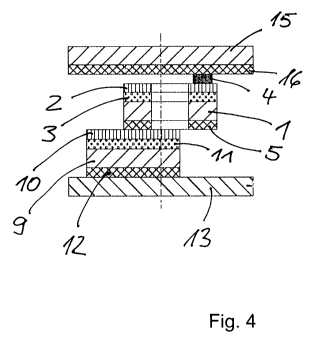
Fig. 3 shows a so-called in-pitch RFID label.
Fig. 4 shows a section through the label of Fig. 3.
Fig. 5 shows a so-called off-pitch RFID label.
Fig. 6 shows a section through the label of Fig. S.
In the method according to Fig. 1, a web-shaped support material
1, to the upper side of which a coupling antenna 2 is glued by
means of an adhesive layer 3, is removed in station 1.5 a. An
RFID chip 4, which is galvanically connected with the coupling
antenna 2, is fastened to the coupling antenna 2. An adhesive
layer 5, which is covered by a removable web-like separating
material 7, is arranged on the back of the support material 1.
Preferably, the support material 1 is made of paper and the
separating material 2 of a silicone paper. In the embodiment
according to Fig. 1, the coupling antennas 2 can also be arranged
on a support material comprised of polyester or imprinted on the
support material with an aluminum-containing ink.
After removing the coupling antenna material in station 1.5 a,
the separating material 7 of silicone paper is first removed and
wound up in the station 1.5 b. In the embodiment according to
Fig. 1, the remaining coupling antenna material is conveyed to a
vacuum drum in station 1.9, on which a cutter drum 8, is arranged
in order to isolate the coupling antennas 2 when required.
In station 1.4, an antenna foil 9 is unwound on the upper side of
which secondary antennas 10 are glued at regular intervals by
means of an adhesive 11. The antenna foil 9 has an adhesive
CA 02696091 2010-02-10
4
layer 12 on its lower side which is covered by a removable
separating material 13, preferably made of silicone paper. In
station 1.9, a coupling antenna 2 with chip 4, separated by the
cutter drum 8, is glued on each secondary antenna 10. In the
event that the distance in direction of travel of the coupling
antennas 2 with chip 4 and the distance in direction of travel of
the secondary antennas 10 is the same, the coupling antenna 2
with chip 4 can also be glued "in-pitch" onto the secondary
antenna 10 in an endless manner without separation by the cutter
drum 8. In this way, a self-adhesive UHF inlay is produced which
can be conveyed for further processing. The self-adhesive
secondary antennas 10 conveyed via station 1.4 were produced
either by etching, printing or punching. Preferably, the self-
adhesive secondary antennas 10 described in the German Patent
Application 10 2007 026 720 are used which are punched out of an
aluminum foil of 1 m - 20 m, preferably about 10 m, and glued
to the front side of an adhesive material 9. On its back, the
adhesive material is provided with an adhesive layer 12 which is
covered by a removable support material 13. When these so-called
aluminum/adhesive antennas are removed in the station 1.4, then
an adhesive material 14 is removed in station 1.2 which,
subsequent to station 1.9, is laminated onto the antenna material
9 with the punched-out secondary antenna 10 and the already
glued-on chip module comprised of coupling antenna 2 and chip in
station 2.4. The adhesive material 14 consists of a paper cover
material 15 which has an adhesive layer 16 on its lower side
which, when removed from the roll in station 1.2, is covered by a
separating material 17 of silicone paper. Prior to lamination,
the separating material 17 is removed in station 1.1 and wound up
into a roll. After the lamination of the cover material 15, a
self-adhesive endless UHF inlay is produced which contains all
components required for an RFID label. It can be conveyed
directly to the punching station 2.5 where the cover material 15
CA 02696091 2010-02-10
is punched out to form individual sections, so that several
spaced, removable and self-adhesive RFID labels are produced on
the endless separation material 13, which are shown in Figs. 3
and 4. The punch grating resulting as waste during punching is
wound up into a roll in station 2.2. The web-like separating
material 13 with the self-adhesive labels found thereon is wound
up into a roll as end product in station 2.3.
If an off-pitch RFID label is produced, as shown in Figs. 5 and
6, then the self-adhesive RFID inlay is inserted in a larger
label size. For this purpose, in station 2.9, label material
consisting of a printable paper cover material 18, which has an
adhesive layer 19 on its back that is covered by a separating
material 20 of silicone paper, is unwound from a roll. The cover
material 18 with the adhesive layer 19 is first separated bythe
separating material 20 in station 2.7. While the cover material
18 is conveyed back in a large loop, the individual RFID inlays
are glued to the separating material in station 2.7 in such a way
that, independent of the label length, an RFID inlay is glued on
for each label. The separating material 20 with the inlays is
then joined again with the cover material 18 at the start of
station 2.5. A relamination of the label material takes place.
The individual labels are then punched out in station 2.5,
wherein the silicone paper 20 remains endless and the removed
punch grating is wound up into a roll in station 2.2. The
endless silicone paper 20 with the RFID self-adhesive labels
adhering thereto is then wound into a roll in station 2.3.
Beforehand, each punched-out RFID label is checked for its
correct function by means of an HF or UHF reader and perhaps
marked or provided with an inscription, for example, by means of
an inkjet printer.
In the method according to Fig. 2, a web-like aluminum/adhesive
CA 02696091 2010-02-10
6
composite material is used as starting material for the
production of the coupling antennas 2, said composite material
consisting of a support material to the upper side of which
coupling antennas 2 are fastened which are punched out of a thin
aluminum foil having a thickness of 1 m - 20 m, preferably of
about 10 m, on which an RFID chip electrically connected with
them is arranged on each coupling antenna. The back of the
support material 1, which preferably consists of paper, has an
adhesive layer 5 which is covered by a separating material 7 of
silicone paper. The aluminum/adhesive composite is removed from
a roll by advancing rolls in station 1.5 a and conveyed to the
adhesive material 14 removed in station 1.2. The coupling
antennas 2 are glued onto the lower side of the cover material 15
after the silicone support 17 of the adhesive material 14 has
been removed and wound in station 1.1. At the same time, the
separating material 7 is removed from the aluminum/adhesive
composite of the coupling antennas 2 and wound up into a roll in
station 1.5 b. In this way, the adhesive layer 5 on the lower
side of the coupling antennas 2 is exposed against which the
antenna material 9 is then moved "in-pitch" in such a manner that
the secondary antenna 10 firmly adheres to the lower side of the
cover material 15 with the adhesive layer 16 and the adhesive
layer 5 of the coupling antenna 2 and in this way produces an
inductive connection with the coupling antenna 2 and the
secondary antenna 10. The separating material 13 of the antenna
material 9 is subsequently removed and wound into a roll in
station 1.7. The distribution into individual RFID labels arid
the delivery to the silicone support 20 of the label material in
station 2.7 takes place subsequently in the manner described in
association with the method according to Fig. 1. The same
applies for the subsequent relamination, the punching-out of the
individual labels in station 2.5, the checking of the proper
working order and winding of the end product into a roll in
CA 02696091 2010-02-10
7
station 2.3.
Preferably, all support materials of the finished label are made
of paper and all antennas of aluminum. This enables a cost-
saving and environmentally friendly production as these materials
are recyclable and a minimum number of materials is used.
Furthermore, it is advantageous if all adhesive layers exposed
after the label has been removed from the silicone paper foil 18
are made of the same adhesive. In the embodiments according to
Figs. 4 and 6, these are the adhesive layers 12, 5, 16 and 19
which are at least partially uncovered when the label is glued
onto a product. Thus, in the finished RFID label, there is a
continuous adhesive layer comprised of one adhesive. In this
way, it is ensured that there are no difficulties which could be
caused by another adhesive for the RFID inlay when the label is
glued on. If the support materials are also all made of paper,
then no separate inlay material is required for the RFID inlay.
A part of the label material can be separated for the inlay..
This applies for the complete inlay material, including the
support materials for the coupling antenna and the secondary
antenna.