Note: Descriptions are shown in the official language in which they were submitted.
CA 02696116 2010-02-24
TITLE OF THE INVENTION
HANDY TERMINAL FOR WIND TURBINE GENERATOR AND WIND
TURBINE GENERATOR
BACKGROUND OF THE INVENTION
Field of the Invention
[0001]
The present invention relates to a handy terminal
for selectively switching an operation mode and a
maintenance mode of a wind turbine generator so that
each operation predetermined in each mode for a wind
turbine generator is performed, respectively, and a
wind turbine generator including the handy terminal.
In particular, the invention relates to a handy
terminal for a wind turbine generator including a tower
provided to stand on the ground or on the water, a
nacelle supported on the tower to be controlled to
rotate in the yaw direction, and a plurality of
rotatable blades to be controlled to move their pitch,
and a wind turbine generator including the handy
terminal. The handy terminal is connectable to the
connectors respectively provided on the lower portion
of the tower and the nacelle so as to output operating
signals for the operation or maintenance of the wind
turbine generator.
- 1 -
CA 02696116 2010-02-24
Description of the Related Art
[0002]
In recent years, the use of a wind turbine
generator to generate renewable energy has become
popular in view of environmental preservation.
A large size wind turbine generator often adopts
the so-called a nacelle type wind turbine generator
comprising a rotor head equipped with blades, a nacelle
accommodating a drive train and a generator, and a
tower supporting the nacelle. The drive train is for
transmitting a torque from the rotor head side to the
generator side, and usually includes a speed increasing
gear so that rotational speed of the rotor head is
increased to transmit to the generator. In order to
achieve the effective utilization of the wind energy
and the stable supply for the commercial line, the wind
farm is composed of a plurality of the nacelle type
wind turbine generator within a predetermined area.
For example, a prior art for maintenance of a plurality
of the wind farm is discloses in Japanese Unexamined
Patent Application Publication No. 2009-287453 (Patent
Publication 1).
[0003]
In the maintenance of the wind turbine generator,
there is a case in which the rotational shaft (and the
rotor head coupled to the rotational shaft) is required
to rotate.
2 -
CA 02696116 2010-02-24
For example, when greasing the main shaft bearing
of the wind turbine generator, it is required to
perform such greasing with rotating the rotational
shaft slowly in order to supply grease uniformly on the
whole bearing. When detaching or attaching the blades,
it is required to rotate the rotor head to a position
in which the blade to be detached or attached are in
the horizontal direction. In the maintenance of some
types of wind turbine generator, the rotational shaft
is locked by a lock pin to prohibit the rotational
shaft from rotating in view of the safety. In such
case, it is required to rotate the rotational shaft to
a position in which the lock pin can be inserted the
hole of the rotational shaft.
[0004]
One simple and easy manner for rotating the
rotational shaft of the wind turbine in such case could
be to rotate a brake disk attached to the rotational
shaft in the subsequent portion of the speed increasing
gear by hand, or to rotate by manually changing the
pitch angle of the blades to rotate the rotational
shaft utilizing the wind turbine.
[Prior Art]
[0005]
[Patent Publication 1] Japanese Unexamined Patent
Application Publication No. 2009-287453
- 3 -
CA 02696116 2010-02-24
SUMMARY OF THE INVENTION
[00061
It was difficult to rotate the rotational shaft to
a predetermined position accurately in such manner. In
addition, a manner for making the work safer is
required.
In the conventional apparatus, since the
maintenance operation of the wind turbine generator by
the control device and the rotating operation are
separate from each other, it is required to separately
perform each of the operations and therefore the
working efficiency was not enough. The art shown in
the Patent Publication 1 is taking information related
to the operating state of the wind turbine generators
in each wind farm via a network being able to
communicate with each wind turbine generator, but the
art is not separately controlling each wind generator
in the wind farm.
[00071
Accordingly, the present invention was made to
solve the above problems, by providing a handy terminal
for a wind turbine generator and a wind turbine
generator including the handy terminal, being able to
improve the safety and the work efficiency in a
maintenance work such as greasing work with rotating a
rotational shaft.
[00081
4 -
CA 02696116 2010-02-24
The present invention provides a handy terminal
for a wind turbine generator, comprising a connecting
portion connectable to a connector provided in the wind
turbine generator, an operating ends group including an
operating end to generate an operating signal which
selectively validates a control logic within a control
circuit provided in the wind turbine generator, and a
display portion for displaying the operating state of
the operating ends group, wherein the operating ends
group includes a mode selecting button for selectively
validating one of a maintenance mode and an operating
mode; and a rotor turning button for switching to the
blades pitch control state (hereinafter referred to as
"rotor turning state") in which blades of the wind
turbine generator side are driven in the predetermined
low speed with adjusting the pitch angle of the blades
according to the rotational speed.
[0009]
According to the present invention, the operating
ends group includes the rotor turning button for
switching to the rotor turning state to rotate the
blades of the wind turbine generator side in the
predetermined low speed, and thereby the blades (namely,
the rotational shaft) can be operated to rotate in the
predetermined low speed by the handy terminal. Thus,
the efficiency of the maintenance work such as greasing
can be improved.
- 5 -
CA 02696116 2010-02-24
[0010]
Preferably, the operating ends group is composed
of a touch panel displayed on the display portion, the
handy terminal includes a panel control unit for
displaying an aimed operating button on the touch panel,
and the rotor turning button is displayed on the touch
panel by the panel control unit when the maintenance
mode is selected by the mode selecting button.
[0011]
In such arrangement, the panel control unit
displays the aimed operating button on the touch panel,
thereby the display for selecting button and the
operating switch are displayed in the same screen so as
to enable the visually easy operation. Further, the
rotor turning button is displayed on the touch panel by
the panel control unit when the maintenance mode is
selected by the mode selecting button, and therefore
the wind turbine generator is prohibited to be changed
to the rotor turning state when the maintenance mode is
not selected. Thus, the safety in the maintenance work
can be improved.
[0012]
Preferably, in the wind turbine generator
including a nacelle supported on the a tower provided
to stand on the ground or on the water, and a plurality
of blades rotatably supported to the nacelle, the
connecting portion is connectable to the connectors
- 6 -
CA 02696116 2010-02-24
respectively provided on the lower portion of the tower
and the nacelle, and wherein the handy terminal
comprises an operating button control unit for
controlling the display of the operating button for
generating the operating signal on the touch panel or
controlling validity/invalidity of operation by the
operating button.
[0013]
In such arrangement, the connecting portion is
connectable to any of the connectors respectively
provided on the lower portion of the tower and the
nacelle, thereby the operator can select the connector
according to his work, and therefore the efficiency of
the work can be improved. Further, the handy terminal
comprises an operating button control unit for
controlling the display of the operating button for
generating the operating signal on the touch panel or
controlling validity/invalidity of operation by the
operating button, and thereby it is possible to display
the operation button according to a kind of the work or
to control validating/invalidating of the operating
button. Thus, the operational perormance of the handy
terminal can be improved.
[0014]
Preferably, the operating button control unit
displays an operating right selecting button for
selecting one of a control circuit connected to the
- 7 -
CA 02696116 2010-02-24
connector of the nacelle side and a circuit connected
to the connector of the tower side, and the ON
operation of the rotor turning button is validated when
the connecting portion of the handy terminal is
connected to the control circuit granted the operating
right by the operation of the operating right selecting
button, and the ON operation of the rotor turning
button is invalidated when the connecting portion of
the handy terminal is connected to the control circuit
not granted the operating right by the operation of the
operating right selecting button.
[0015]
In such arrangement, the ON operation of the rotor
turning button is validated only in the control circuit
of which the operating right is selected, and is
invalidated in the control circuit of which the
operating right is not selected. Therefore, it is
possible to prevent the unstable performance of the
control for the maintenance work caused by the mixed
operating signals sent from two control circuits or the
deterioration of the safety of the maintenance work.
[0016]
Preferably, the operating button control unit does
not permit operation of any button other than the rotor
turning button after the rotor turning button is turned
ON. Thereby, the other operations are prohibited to be
performed during performing of the rotor turning so
- 8 -
CA 02696116 2010-02-24
that the safety of the maintenance work can be improved.
[0017]
In another aspect, the present invention provides
a wind turbine generator including a nacelle supported
on a tower provided to stand on the ground or on the
water, and a plurality of blades rotatably supported to
the nacelle, comprising: a connector provided on the
nacelle or the lower portion of the tower and
connectable to the handy terminal as set forth in claim
1; a control circuit for switching to a maintenance
mode to place the blades in feathering state (stopping
of the rotation) when receiving the maintenance mode
selecting signal from the mode selecting button of the
handy terminal, and switching to the rotor turning
state for rotor turning the blades based on the On
operating signal of the rotor turning button in the
state of the maintenance mode.
[0018]
In such arrangement, the control circuit of the
wind turbine generator includes a control logic for
switching to a maintenance mode to place the blades in
feathering state and the rotor turning state for rotor
turning the blades, and these states are switched based
on the ON operating signal of the rotor turning button
from the handy terminal, and therefore it is possible
to easily change the state of the blades from the handy
terminal according to the maintenance work. Thus, the
- 9 -
CA 02696116 2010-02-24
efficiency of the work can be improved.
[0019]
Preferably, the control circuit validates the ON
operating signal of the rotor turning button, when the
connecting portion is connected to the connector
provided in the nacelle side.
In such an arrangement, it is possible to prevent
the unstable performance of the control for the
maintenance work caused by the mixed operating signals
sent from two control circuits. In general, when the
blades is switched to the rotor turning state for
greasing to the main shaft, preparing of detaching or
attaching of the blades, or inserting the lock pin,
such work is performed nearby the nacelle. Thus, the
efficiency of the work and the safety of work can be
improved by validating the ON operating signal of the
rotor turning button when the connecting portion is
connected to the connector provided in the nacelle side.
[0020]
Preferably, the control circuit does not permit
operation of any button other than the rotor turning
button after validating the ON operating signal of the
rotor turning button. In such arrangement, any other
operation is not performed in the rotor turning state,
and therefore the safety of the work can be improved.
[0021]
Preferably, the control circuit keeps only the yaw
- 10 -
CA 02696116 2010-02-24
control state of the nacelle and resets the other
maintenance control mode when receiving an operation
signal for switching to the maintenance mode from the
handy terminal or an external remote control terminal.
In such arrangement, when receiving such operating
signal, the other maintenance control mode is reset,
and therefore it is possible to normally operate the
wind turbine generator after the operation mode was
switched.
[0022)
According to the present invention, as mentioned
above, the operating ends group includes the rotor
turning button for switching to the rotor turning state
to rotate the blades of the wind turbine generator side
in the predetermined low speed, and thereby the blades
(namely, the rotational shaft) can be operated to
rotate in the predetermined low speed by the handy
terminal. Thus, the efficiency of the maintenance work
such as greasing can be improved.
Further, the control circuit of the wind turbine
generator includes a control logic for switching to a
maintenance mode to place the blades in feathering
state and the rotor turning state for rotor turning the
blades, and these states are switched based on the ON
operating signal of the rotor turning button from the
handy terminal, and thereby it is possible to easily
change the state of the blades from the handy terminal
- 11 -
CA 02696116 2010-02-24
according to the maintenance work. Thus, the
efficiency of the work can be improved.
BRIEF DESCRIPTION OF THE DRAWINGS
[0023]
FIG. 1 is a schematic diagram showing a wind
turbine generator site according to an embodiment of
the present invention.
FIG. 2 is a diagram showing an example of the
construction of the wind turbine generator.
FIG. 3 is a block diagram showing a handy terminal
and the wind turbine generator related to the
embodiment.
FIG. 4 is a sequence diagram showing processes of
the handy terminal and the wind turbine generator.
FIG. 5 is a flowchart showing a function of the
handy terminal.
FIG. 6 is a diagram showing an example of the
startup screen.
FIG. 7 is a diagram showing an example of the
rotor turning setting screen.
FIG. 8 is a graphic diagram showing a relationship
between the rotational speed and the pitch angle.
DETAILED DESCRIPTION OF THE PREFERRED EMBODIMENTS
[0024]
A preferred embodiment of the present invention
will now be described in detail with reference to the
- 12 -
CA 02696116 2010-02-24
accompanying drawings. It is intended, however, that
unless particularly specified, dimensions, materials,
shape, its relative positions and the like shall be
interpreted as illustrative only and not limitative of
the scope of the present.
[0025]
Referring first to FIG. 1, the skeleton of a wind
turbine generator site including a plurality of wind
turbine generators will be described.
A wind turbine generator site 10 includes a
plurality of wind turbine generators 1, whereby these
wind turbine generators 1 generates electricity
utilizing wind power as energy. The electricity
generated by the wind turbine generators 1 is supplied
to an electric line 53 through a step-up transformer 51
and a grid connected board 52.
[0026]
The wind turbine generators 1 are equipped with at
least one control circuit 13, respectively. The
control circuit 13 includes a control logic to perform
a driving operation or a maintenance operation of the
other wind turbine generator 1. Preferably, the
control logic included in the control circuit 13 is a
control logic common to the other wind turbine
generator. The control circuit 13 is connected to a
connector 11 so as to a variety of operating signals
can be input to the control circuit from a handy
- 13 -
CA 02696116 2010-02-24
terminal 20.
[0027]
The wind turbine generator site 10 may includes a
communications management system as described below:
The communications management system is for remote
controlling and monitoring the wind turbine generators
1, and includes a management device 56 provided in the
spot of the site 10, and a remote monitoring device 57
connected to the management device 56 via a
communication line. The management device 56 is
connected to a hub 55 via a communication cable while a
plurality of control lines extended from the control
circuits 13 are connected to the hub 55. Each of the
management device 56 and the remote monitoring device
57 comprises a computer including CPU, ROM, RAM, memory
and a communication interface, etc., and mainly
monitors the operating condition of the wind turbine
generators 1.
[0028]
Here, the specific construction of the wind
turbine generator 1. FIG. 2 is a diagram showing an
example of the construction of the wind turbine
generator.
A wind power generator 1 mainly includes a tower 2
provided to stand on the foundation set on the ground
or on the water, a nacelle 3 provided on the upper end
of the tower 2, a rotor head 4 provided on the nacelle
- 14 -
CA 02696116 2010-02-24
3, a plurality of blades 5 attached to the rotor head 6,
and a pitch driving device for driving the blades 5 in
the pitching direction.
[0029]
The tower 2 has a column-like shape extending
upwardly from the foundation. The tower 2, for example,
can be made from a single column-like member or made
from a plurality of units aligned in upright direction
and coupled each other. If the tower 2 is made from
the plurality of units, the nacelle 3 is provided on
the unit located on the top of the tower 2.
The nacelle 3 supports the rotor head 4 and
accommodates a drive train 10 and a generator 18, etc.
The drive train 7 includes a main shaft 71
connected to the rotor head 4, a speed increasing gear
72 coupled to the main shaft 71, and a coupling 73 for
connecting the speed increasing gear 72 to a generator
8.
[0030]
The main shaft 71 is connected the rotor head 4 so
that the main shaft 71 can be rotated with the blades 5
and the rotor head 4, while the main shaft 71 is
rotatably supported to the casing side of the nacelle 3
by a main shaft bearing.
The speed increasing gear 72 is provided between
the main shaft 71 and the coupling 73, and increases
the rotational speed input from the main shaft 71 then
- 15 -
CA 02696116 2010-02-24
outputs to the coupling 73. The speed increasing gear
72 is not limited a special type of mechanism, but, for
example, can be composed by combination of a planetary
gear type mechanism and a spur gear type mechanism
(both of them are not shown).
The pitch driving device 6 rotates the blades 5
around its axis (a dashed line in the drawing) so as to
change the pitch angle of the blades 5.
[0031]
The wind turbine generator 1 is further equipped
with a control circuit 13 (13A, 13B) for controlling
system of the wind turbine generator 1.
The control circuit 13 includes the tower side
control circuit 13A provided in the tower 2 and the
nacelle side control circuit 13B accommodated within
the nacelle 3. Both control circuits 13A and 13B are
electrically connected to each other.
[0032]
FIG. 3 is a block diagram showing a handy terminal
and the wind turbine generator related to the
embodiment.
Each of the connector 11 of the wind turbine
generator 1 and a connecting portion 21 of the handy
terminal 20 is the standardized specification among the
plurality of the wind turbine generator 1 so that the
handy terminal 20 is connectable to any of the wind
turbine generators 1.
- 16 -
CA 02696116 2010-02-24
The connecting portion 21 of the handy terminal 20
may be connected directly to the connector 11 of the
wind turbine generator 1, or may be connected through a
transmission cable to the connector 11 of the wind
turbine generator 1. The data is transmitted from the
handy terminal 20 to the wind turbine generator 1 by
such connecting manner, and thereby the amount of the
data transmitting is increased. Thus, the operating
signals of the plurality of the control logics can be
transmitted in a short time.
[0033]
The wind turbine generator 1 will be described.
The wind turbine generator 1 mainly includes the
connector 11, an input-output interface 12, and the
control circuit 13 having the control logics 14, 15.
[0034]
The control circuit 13 receives the operating
signals input from the handy terminal 20 through the
connector 11 or signals detected by various sensors,
performs various processes to generate control signals,
and sends these control signals to various devices.
The control circuit is composed of a hardware
including CPU, ROM, RAM and memory, etc. Preferably,
each function of the control logics 14, 15 is achieved
by these hardware. This embodiment shows an example in
which each of the control logics 14, 15 is achieved by
software, however, each of the control logics can be
- 17 -
CA 02696116 2010-02-24
constituted by hardware logic (logic circuit).
[00351
The input-output interface 12 receives signals
from the handy terminal 20, various sensors, and
various devices, etc., tranfers the signals to each
control circuit 13, and transmits the control signals
generated by the control circuit 13 to various devices.
It should be noted that the input-output interface 12
can be defined as including the connector 11.
In the control logics 14, 15, an operating
condition is set based on the operating signals al, a2,
whereby the control logics 14, 15 process under this
condition to generate control signals bi, b2.
Operating signals al, a2 include a selecting
signal for selectively validate the control logic or a
numeric signal for setting a condition of the control
logic. These operating signals al, a2 are input to the
control circuit 13 so that valid/invalid of the control
logic is set or numeric condition is input to the
control logic, and thereby the control signals B1, B2
are generated by the control logic under the operating
condition.
[00361
In the embodiment, the control logic includes at
least a rotor turning control logic 14 for controlling
the pitch driving device 6. The rotor turning control
logic 14 is for controlling the blades 5 of the wind
turbine generator 1 in a blades pitch control state
- 18 -
CA 02696116 2010-02-24
(herein after referred to "rotor turning state") in
which the blades is rotated in a predetermined low
speed with adjusting the pitch angle of the blades
according to the rotational speed.
[0037]
The rotor turning state is, for example, performed
as the following.
As shown in Fig. 8, the pitch angle of the blades
has correlation with the rotational speed. Thus, the
rotor turning control logic 14 detects the rotational
speed of the blades (or the rotational shaft or the
rotor head connected to the rotational shaft), and
calculates the deviation between the detected value and
the target value of the rotational speed, and performs
the PI control based on the deviation so that the
rotational speed stabilizes at the target value with
adjusting the pitch angle, while driving the wind
turbine generator in low speed.
[0038]
Preferably, the control logic includes emergency
magnet valve control logic 15 for controlling an
emergency magnet valve 9.
In general, the wind turbine generator 1 includes
a main oil pressure line for driving main devices of
the wind turbine generator by the oil pressure, such as
a blades pitch, a main shaft brake and a yaw brake,
etc., and a magnet valve provided in the main oil
pressure line controls the supply/exhaust of the oil
- 19 -
CA 02696116 2010-02-24
pressure to the devices. Moreover, the emergency
magnet valve 9 is provided in an emergency line
connected to the main oil pressure line. The operating
oil is conducted to the main oil pressure line by
energizing (closing) the emergency magnet valve so that
the devices are controlled to drive. On the other hand,
the operating oil is exhausted from the main oil
pressure line by non-energizing (opening) the emergency
magnet valve so that the wind turbine generator 1 is
stopped.
[0039]
The control circuit 13 may include a plurality of
control logics as described above. In the plurality of
the wind turbine generator 1 provided in the same site,
each of the wind turbine generators preferably includes
such combination of control logics as being common
among the wind turbine generators 1. Thus, the control
circuit 13 includes such common logic which is
applicable to the other wind turbine generator 1 in the
same site, thereby being possible to standardize the
construction of the control circuit 13, and therefore
the cost reduction can be achieved.
[0040]
The construction of handy terminal 20 will be
described.
The handy terminal 20 mainly includes the
connecting portion 21, an operating ends group 22 and a
display portion 24. The handy terminal 20 may further
- 20 -
CA 02696116 2010-02-24
include a panel control unit 28, an operating button
control unit 29 and a screen display control unit 30.
The handy terminal 20 selectively switches a drive
operating mode and a maintenance mode so as to perform
a predetermined control corresponding to each switched
mode.
[00411
The display portion 24 displays the operating
state of the operating ends, and a liquid crystal
display is used as the display portion.
The operating ends group 22 generates an operating
signal for selectively validating the control logic
within the control circuit 13 installed in the wind
turbine generator 1. The operating ends group 22 may
be composed of a key board provided separately from the
display portion 24. Preferably, the operating ends
group 22 is composed of a touch panel 23 operable by
touching on the screen surface of the display portion
24. It is possible to adopt the common method (for
example, a resistive layer method) as the operating
method for the touch panel 23.
[00421
The operating ends group 22 includes a mode
selecting button 25 for selectively validating one of a
maintenance mode and an operating mode; and a rotor
turning button 26 for switching the blades of the wind
turbine generator 1 to the rotor turning state when the
maintenance mode is selected by the mode selecting
- 21 -
CA 02696116 2010-02-24
button 25, and an operating right selecting button 27
for selecting one of the control circuits 13 to be
granted an operating right.
Thus, the operating ends group 22 of the handy
terminal 20 includes the rotor turning button 26, and
thereby the blades 5 (or the rotational shaft) can be
operated to rotate in the predetermined low speed by
the handy terminal 20. Thus, the efficiency of the
maintenance work for the wind turbine generator 1 can
be improved.
[0043]
The panel control unit 28, which is provided in
case that the operating ends are composed of the touch
panel 23, displays the aimed operating button, and
generates an operating signal when detecting pressure
to the operating button on the touch panel 23. Thus,
the panel control unit 28 displays the aimed operating
button on the touch panel 23, and thereby the display
for selecting button and the operating switch are
displayed in the same screen so as to enable the
visually easy operation. Preferably, the rotor turning
button 26 is displayed on the display portion 24 by the
panel control unit 28 when the maintenance mode is
selected, and thereby the wind turbine generator 1 is
prohibited to be switched to the rotor turning state
when the maintenance mode is not selected. Thus, the
safety in the maintenance can be improved.
[0044]
- 22 -
CA 02696116 2010-02-24
The operating button control unit 29 mainly
controls display on the display portion 24 of the
operating buttons of the operating ends group 22 or
validity/invalidity of operation of the operating
buttons. The operating button control unit 29 enables
the operating buttons to be displayed on the display
portion 24 according to a kind of the work or enables
validity/invalidity of operation of the operating
buttons to be controlled, and therefore the operational
performance of the handy terminal can be improved.
Particularly, in case that one wind turbine generator 1
includes a plurality of the control circuits 13A, 13B,
the operating button control unit 29 controls
displaying on the display portion 24 or
validity/invalidity of operation of the operating
buttons according to the necessity, thereby it is
possible to prevent the unstable performance of the
control for the maintenance work caused by the mixed
operating signals sent from two control circuits or the
deterioration of the safety of the maintenance work.
[0045]
In case that a plurality of the control circuits
13 exist, the operating button control unit 29
preferably includes a function to grant one of the
control circuits 13 an operating right. The operating
right is for setting validity/invalidity of the
operation input from the operating button. The
operating button control unit 29 accepts the operation
- 23 -
CA 02696116 2010-02-24
from the handy terminal 20 which is granted the
operating right, while rejecting the operation from the
handy terminal 20 which is not granted the operating
right. Instead, it is possible to set, in advance, the
operating button on which the restriction for
validity/invalidity of the operation is placed, however
in particular, the ON operation of the rotor turning
button 26 has to abide by the operating right.
Thus, the ON operation of the rotor turning button
26 is validated only in the control circuit 13 of which
the operating right is selected, and is invalidated in
the control circuit 13 of which the operating right is
not selected, and therefore the safety of the
maintenance work can be improved more securely.
[0046]
Preferably, the operating button control unit 29
does not permit operation of any button other than the
rotor turning button 26 after the rotor turning button
26 is turned ON, and thereby the other operations are
prohibited to be performed during controlling of the
rotor turning so that the safety of the maintenance
work can be improved.
[0047]
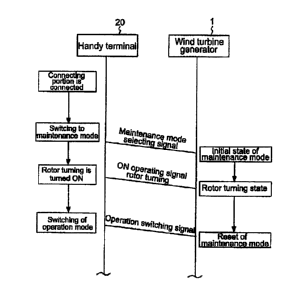
Next, referring to Fig. 4, the sequence of the
wind turbine generator 1 and the handy terminal 20 will
be described.
If the connecting portion 21 of the handy terminal
- 24 -
CA 02696116 2010-02-24
20 is connected to the connector 11 of the wind turbine
generator 1 and the maintenance mode is selected, the
handy terminal 20 is switched to the maintenance mode.
The wind turbine generator 1 sets the maintenance
mode when receiving the maintenance mode selecting
signal from the handy terminal 20. In the maintenance
mode, at least the wind turbine generator 1 is switched
to the maintenance control mode in which at least the
blades 5 are in the feathering state (rotation stopped).
[0048]
Further, if the rotor turning button 26 of the
handy terminal 20 is turned ON and the control circuit
13 receives the ON operating signal of the rotor
turning button 26, the blades 5 are controlled to be in
the rotor turning state. The maintenance work such as
the greasing is performed preferably when the blades 5
are kept in the rotor turning state.
Thus, the control circuit 13 includes the control
logic to switch the maintenance mode control in which
the blades 5 are placed in the feathering state and the
rotor turning state in which the blades 5 is placed in
the rotor turning state, and switches the these control
modes based on the operating signal from the handy
terminal 20, therefore enabling to easily switch the
state of the blades 5 using the handy terminal 20
according to the maintenance work so that the
efficiency of the work can be improved.
25 -
CA 02696116 2010-02-24
[0049]
If the maintenance work is completed and the
operation switching signal to the operation control
mode is input by the mode selecting button 25 of the
handy terminal 20, then the control circuit 13 resets
the maintenance mode according to the operation
switching signal.
[0050]
Preferably, the control circuit 13 keeps only the
yaw control state of the nacelle and resets the other
maintenance control mode when receiving an operation
switching signal from the handy terminal 20 or an
external remote control terminal (for example, the
management device 56 or the remote monitoring device 57,
etc., shown in Fig. 1) in the maintenance mode. Thus,
the control circuit 13 resets the maintenance mode when
receiving such operation switching signal, and thereby
enabling the wind turbine generator 1 to be driven
normally.
[0051]
Referring to Figs. 5 to 7, the specific operation
of the handy terminal 20 will be described. FIG. 5 is
a flowchart showing a function of the handy terminal.
FIG. 6 is a diagram showing an example of the startup
screen. FIG. 7 is a diagram showing an example of the
rotor turning setting screen.
It should be noted that the flowchart is, as an
- 26 -
CA 02696116 2010-02-24
example, directed to the wind turbine generator 1
including the tower side control circuit 13A provided
in the lower part of the tower and the nacelle side
control circuit 13B accommodated in the nacelle.
[0052]
First, the connection portion 21 of the handy
terminal 20 is connected to the connector 11 of the
wind turbine generator 1 (Sl), then, a startup screen
is displayed after an electric source of the handy
terminal 20 is ON (S2) . One example of the startup
screen is shown in Fig. 6. An operation right
selecting button 101 for setting the operation right
and a mode selecting button 104 for selecting one of
the maintenance mode and operation control mode are
displayed on the startup screen 100
The operation right selecting button 101 includes
a tower button (a tower side control circuit button)
102 and a nacelle button (a nacelle side control
circuit button) 103, and the operator pushes the button
for the side connected with the handy terminal 20 to
select the control circuit 13 (S3).
[0053]
If the nacelle button 103 is pushed, the control
circuit 133 of the nacelle side is granted the
operation right so that the operating signal from the
handy terminal 20 connected to the control circuit 13B
of the nacelle side is accepted (S4) At this point,
- 27 -
CA 02696116 2010-02-24
the operating signal (in particular, an ON operating
signal of the rotor turning) from the handy terminal 20
connected to the control circuit 13A of the tower side
is not accepted.
On the other hand, if the tower button 102 is
pushed, the control circuit 13A of the tower side is
granted the operation right, the operating signal from
the handy terminal 20 connected to the control circuit
13A of the tower side is accepted (S5). At this point,
the operating signal (in particular, an ON operating
signal of the rotor turning) from the handy terminal 20
connected to the control circuit 13B of the nacelle
side is not accepted.
[0054]
The following steps are operation of the handy
terminal 20 for the control circuit 13 in the selected
side.
If the operation right for the control circuit 13
is selected, then the operator selects the mode by the
mode selecting button 104 (S6) The mode selecting
button 104 includes a maintenance mode button 105 and
an operation control button 106. If the operation
control button 106 is pushed, the wind turbine
generator 1 is switched to the operation control mode
(S7). If the maintenance mode button 105 is selected,
the wind turbine generator 1 is switched to the
operation control mode (S8). The explanations for the
- 28 -
CA 02696116 2010-02-24
processes of the operation control mode are omitted.
[0055]
If the wind turbine generator 1 is switched to the
maintenance mode, a rotor turning setting screen is
displayed. One example of the rotor turning setting
screen is shown in Fig. 7. An emergency magnet valve
button 111 and a rotor turning button 112 are displayed
on the rotor turning setting screen (S9).
In case that the emergency magnet valve 9 is set
to close in order to prohibit the various devices from
activating as the safety measures in the maintenance
mode, the emergency magnet valve button 111 is pushed
to close the magnet valve 9 in advance.
Then, if the rotor turning button 112 is pushed
(S10), the ON operating signal of the rotor turning is
transmitted to the control circuit 13 (Sil).
The control circuit 13 controls the pitch
activating device 6 based on the rotor turning control
logic so as to perform an automatic rotor turning on
receiving the ON signal of the rotor turning.
[0056]
As mentioned above, the blades of the wind turbine
generator 1 are switched to the rotor turning state
based on the ON operating signal of the rotor turning
input from the operating ends group 22 such as the
touch panel in the maintenance mode, and therefore the
efficiency of the maintenance work such as greasing can
- 29 -
CA 02696116 2010-02-24
be improved.
30 -